Bearhawk Aircraft Bearhawk Tailwheels LLC Eric Newton's Builder Manuals Bearhawk Plans Bearhawk Store

Announcement

Collapse
No announcement yet.

simple question about rivet positions in ribs-

Collapse
X
 
  • Filter
  • Time
  • Show
Clear All
new posts

  • simple question about rivet positions in ribs-

    Not cut any metal yet-- but i want to ! Thinking about rib making. At some point after I have turned down the outer edge to make the flanges, I will have to fluit.
    The fluits go in between the rivet holes. (spaced evenly and centered im supposing-) So I would want to mark the rivet locations on the edge of the form blocks.
    So how the heck- do i know where the skin rivet locations are ...... Also it should be very important -cosmetically- to have all the rows of rivet heads lined up in
    nice straight lines after skinning. Once those holes are in the ribs I cant adjust them any short of making a new part. So it appears like a lot revolves arround
    finding those hole locations accurately.

    OK- may have answered my own question----- :-)

    Just checked my drawing 3B (wing ribs) - I can see little tick marks representing rivet locations at the top and bottom of the ribs. So it seems like I should make like a
    red sharpie mark on the form block at those locations. maybe make a green mark measured out the be exactly between the red marks. (fluit on green- dont touch red)
    Then have to just figure the correct lengths for each rib by calculating the spar thickness at the different stations. Does that stack of sheets turn out any thicker than the sum
    of the material thicknesses ? that is- does there need to be any slight fudge factor for the primer in the stack or the sheets being only 98% squeezed together ? Or-- is
    that so small that no one notices or cares ? wouldnt think it would be more then .015 at worst.....

    Am I missing anything major here before I start making my master rib model and the rib form blocks and then make a rib or two ?
    Just got my new router table done. i have watched Mr. Snapp's good videos over and over. (thank you so much for those..... I appreciate your woodworkers viewpoint-
    i am an ammatuer violinmaker- so everything you are doing seems straight ahead logical and precice ! )

    Kind of getting excited to be getting close to making product finally !

    Tim

  • #2
    For my LSA, I marked the rivet locations on my backer block and transferred them to the ribs after I hammered over the edges. It definitely helps to keep the flute locations consistent for skinning.

    When it came time to skin, I used a thin mock up skin strip (about 1"wide) over the rib location and "fudged" any location that needed to move a bit. Since the flute locations were consistent rib to rib, this meant that there might be a bit of variance(very little) from one row to the next, the rows themselves were aligned from root to tip.

    Making all the ribs full length vs. making them varying lengths up front has been discussed before. I made mine all full length and trimmed at wing assembly as I felt the value of keeping parts interchangeable as long as possible outweighed the benefits of making several different lengths. But each to their own.

    The wings are a lot of "Make this part, now make a few hundred more ijust like it". I found a bit of extra effort up front making things like rib attach angles identical saved headaches of sorting out similar but slightly different parts later on.

    Comment


    • #3
      Originally posted by fairchild View Post
      Does that stack of sheets turn out any thicker than the sum
      of the material thicknesses ? that is- does there need to be any slight fudge factor for the primer in the stack or the sheets being only 98% squeezed together ? Or-- is
      that so small that no one notices or cares ? wouldnt think it would be more then .015 at worst.....

      Am I missing anything major here before I start making my master rib model and the rib form blocks and then make a rib or two ?
      Just got my new router table done. i have watched Mr. Snapp's good videos over and over. (thank you so much for those..... I appreciate your woodworkers viewpoint-
      i am an ammatuer violinmaker- so everything you are doing seems straight ahead logical and precice ! )

      Kind of getting excited to be getting close to making product finally !

      Tim
      Dont sweat the small stuff like the thickness of primer. If you want to get real exact, the line on the velum airfoil plan represents the outer skin. Your Master Form Block should probably account for the thickness of the skin and the ribs. (making it .045 smaller than the outside of the line on the Velum Airfoil for a Patrol that has .025 ribs and .020 skin)

      But if someone made there form block to match the line of the skin, its is pretty small to be worrying about.

      What sources are you using to help you learn scratch building? Are you familiar with Eric Newton's Bearhawk Wing Manual? Are you familiar with the concept of making a master form block? Consider making the small parts first like the Aileron Pocket Ribs, or the aileron & flap ribs where errors are less costly. The router method for making your blanks will turn out great quality, but be very careful...it is scary when the bit grabs...I was glad when that job was finished and I still could count to ten.
      Brooks Cone
      Southeast Michigan
      Patrol #303, Kit build

      Comment


      • #4
        Bcone-
        I wasnt thinking of the rib height vs. the skin.... so much as the rib LENGTH vs. the spar web stack (in the horizonal).
        I will be ordering newtons manual this week. Looks like good info on many details.
        I thought i would transfer the mylar master rib to art tracing (long roll) paper--- then transfer to mdf. Band saw out-- then put a sanding drum into the router to work it down slowly.
        If I could get it about 1/2 a pencil line smaller than the mylar-- that would seem about right. Be nice if I could find someone to scan and then CNC route my mater rib in MDF.
        Once the master rib is perfect- then its just a matter of copying it accurately with the router table.
        I have a ball bearing copy bit with a 1/2 inch carbide straight 2 fluit cutter. I am concerned that a 1/2 bit might be too large in diameter and that might induce more grabbing--
        Would I want a smaller bit ( like 1/4) and maybe one with 3 or 4 fluits and the fluits spiraled instead of straight ?
        I am considering doing the nose ribs first until I get "warmed up" with the process. We have an outlet for Rockler (and woodcraft) here so I might stop in there and browse router bits.
        I have done some aircraft sheet metal in the past.... but im sure there will be plenty of tricks to learn as I go. Like working smarter instead of harder--- if I can be smart enough.
        Only done a little flush riveting so i will have to re-learn that skill when I get to it. Dont remember it being real hard- just hard on the nerves ! Might decide to get a 2x gun as an
        advantage when I get to those little babys.

        just finished my router table---- is there a preferred bit for cutting 3 or 4 layers of aluminum ?

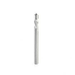
        How about this bit ?


        Tim
        Last edited by fairchild; 10-08-2017, 11:56 PM.

        Comment


        • #5
          The ball bearing copy router bit can be purchased with flutes that eject the waste away from the router base or towards the router base plate. The forces on the bit that ejects the waste towards the base plate will also draw the MDF material that you are routing towards the router base plate as well. I think that helps to stabilize things while you are working. If I recall, that resulted in another problem that all the waste was being drawn into the router. So I fabricated a simple shield to prevent the chips from entering the motor and hopefully improved its life.

          MDF is tough on router bits. Some builders had problems wearing out bearings. I used a 1/2" two flute bit...kind of pricey....and after making all the patterns, and AL blanks, and cutting the lightening holes, and making the discs out of MDF to flange the lightening holes it its time to have them sharpened.

          Just be careful, go slow, and be mindful of the heat buildup on the smaller bits. I used a 1/4 inch bits with a circle cutter tool that attached to the router for the lightening holes in the MDF patterns and over heated I think two of them. Maybe thats why my 1/2" bit lasted longer due to its ability to dissipate the heat.

          You will damage an MDF patten at some point. You don't have to remake it..they are very repairable with bondo. I used the glass reinforced bondo (green label) and it worked pretty good. Before you start whacking on the forming block with your Fluorescent Orange Harbor Freight Dead Blow Mallet, reinforce the edges of the block...I just spread a thin coating of 5 minute epoxy resin and got way better service life from it...not perfect, but much improved.
          Last edited by Bcone1381; 10-09-2017, 01:28 PM.
          Brooks Cone
          Southeast Michigan
          Patrol #303, Kit build

          Comment


          • #6
            Thanks Bcone---- (and others)
            I have been wondering if some of that randolf's 2 part epoxy varnish painted on to the last inch arround the edge would "harden-up" the MDF. I suppose I could make the form blocks
            out of hard maple (if I could afford hard maple) Was thinking that varnish is prett low viscosity and might penetrate- harden and stabilize the MDF. It cuts nice but it isnt the
            strongest stuff in the world. (you can smell the insecticide in it when you route or cut it)
            I have a 1/2 inch bearing carbide copy bit. I will try it and see how it works (straight fluit)

            Tim

            Comment


            • #7
              I just used 5 minute epoxy for the edge of my form block. Held up just fine.

              The backer board needed to be reinforced at the tail area. After having it break a few time, I reinforced it with a piece of aluminum.

              I used clear polyurethane for the router block edges.

              At first, i was pushing the router blocks against the router bearing as I went. This quickly would make the router bearing disintegrate and then I would have to fix the router block. I just made a paste of 5 minute Epoxy and MDF dust and used it as a putty.

              Once I learned to just let the natural cutting pressures of the router hold the forms against the bearing while I kept the work down against the table and simply "guided" it along I had no further problems. I also limited the total thickness of the aluminum to around .070" (two to three layers depending on thickness)

              You do not have permission to view this gallery.
              This gallery has 1 photos.
              Last edited by BTAZ; 10-15-2017, 09:49 AM. Reason: sp

              Comment


              • #8
                seems like I remember they make a liquid that penetrates wood and hardens once inside - cant remember the name now-- one part stuff.
                any idea why the bearings on your bit kept failing ? Maybe the MDF dust was getting inside them.... the guide bearings on my ban saw failed like that.....
                I wouldnt think you could cause them to fail just from hand pressure..... (but I dont know-- only used those type bits short term--)
                T

                Comment


                • N3UW
                  N3UW commented
                  Editing a comment
                  Superglue works very well for that. Go to a hobby store and get a several ounce bottle of the th8n stuff. I got the idea from Desert Bearhawk who is an avid RC builder. That is a technique model builders also use.

              • #9
                The bearing failures were definitely technique.I had very minimal router experience and was very worried about losing control of the parts. Fact is that once the router template is against the bearing and you are feeding in the correct direction the process is pretty smooth. I went through two bearings before I changed from pushing the form against the bearing to just allowing the router cutting pressure to pull it against the form. The last bearing was still fine even after all the cutting was completed.You still need to "control" the work piece(careful feeding it in for the initial cut in particular) but after that you are controlling the feed rate as the cutting forces will keep the router template tight to the bearing.

                You also need to limit the thickness you are cutting. For me, it was typically three or four blanks at a time, depending on rib blank thickness, no more then about .080" total

                I just used a 1/2" two flute bit from Home Depot. After the second bearing failure, I bought a router bit assortment from Harbor Freight(which had something like three bearings in it) and they worked fine.

                The parts come out with their edges held together because the plastic sheeting melts together. I smoothed up the edges with a file while they were still stuck together and then separated the blanks for some minor final deburring.with Scotch Brite

                No reason to try to get too sophisticated with hardening the edge of the form blocks and such. As myself and others have stated, 5 minute Epoxy worked just fine and was handy to have for other reasons during the process.

                Comment

                Working...
                X