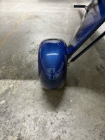
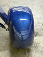
BH5 wheel pants speed/efficiency improvements

dramsey

Bearhawk 5
On Fri, Aug 7, 2026 at 5:12 PM Dennis Ramsey <doramsey@gmail.com> wrote:
I should have probably titled this post Sacrilege, as it is likely the response some of you might have. But I felt important to document what I did and why I did it.

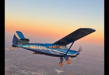
In my view, Bearhawks are the perfect plane for my mission. Its design will get in and out of incredible short strips even with heavy loads, but whats unusual is that it is also fast and relatively efficient in the STOL world.

I built my 5 to be a family camper. I have no intentions of doing STOL competitions nor push my luck landing on sandbars. I had a great STOL plane in a JUST Highlander before the Bearhawk but it was slow and only had two seats. My daughters decided to surprise me in their late 30’s with three grandchildren. I wanted to take them airplane camping and so the JUST was sold and Bearhawk 5 kit bought. From day one I have not yielded to my big tire preaching airpark neighbors(none of which have big tires) because while I like a challenge, I wont take risks with the grandkids on board. Small tires provides a constraint for my male hormones that naturally would lead me to gross episodes of stupidity. I love watching Steve Henry land his Just on a 60 ft mountain top or his infamous dead stick takeoff from a mountain top. I will live vicariously through him.

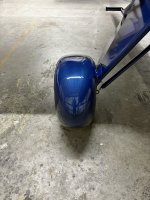
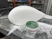
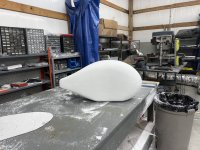
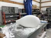
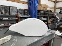
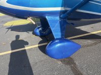
So thats why small tires (7’s) and I also want to do long distant camping runs and want to take my wife to Alaska without having to stop in Canada. The Bearhawks speed and range are therefore important. I was Bearhawk camping on a short grass strip with a C180 driver who started talking wheel pant benefits. My big tire preaching neighbor witnessed it and said oh brother, I see a foam order coming. I did not want to disappoint him so I bought some foam and took pictures of RV wheel pants and was off forming my own carbon fiber wheel pants. After the requisite endless sanding and filling (Photos available upon request), I was done and ready for flight testing.

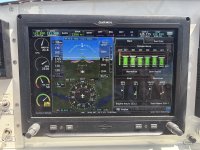
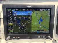
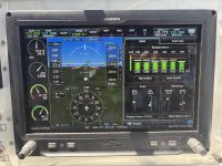
Its soooo difficult to get apples to apples data comparisons but what I can say is the fastest my Bearhawk got at 75% in initial flight testing was 168 MPH true at a fuel burn of 16.4GPH. With the wheel pants I was able to get that same speed LOP at 13.3 Gph. When I lay the new test flights over past flight data I see 7-10 MPH increase but I would have to say the average is closer to 8. When I did the math to take new flights to 75% power the result came back at 7.5 MPH increase so seems close to the same answer. I did not optimize efficiency at all but did test as high as 10500 which gave me 158MPH at 11.8 GPH. I also did descend at 800FPM which produced 185MPH true so I could see if anything excited the wheel pants….but they just seemed pretty bored with the whole thing.

It takes about 5 minutes to remove the wheel pants and through them in the luggage if I feel they might get damaged in a particular intended landing spot,
Side note. You will see that my oil temp is not a fan of 2500 rpm but its well within Lycoming spec. CHT’s are fine.
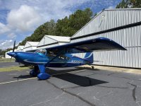
So basically I got almost a 20% range improvement with a little sweat equity and maybe $500 in materials.
 

Attachments

  • IMG_4485.jpeg
    IMG_4485.jpeg
    6.4 MB · Views: 48
  • IMG_4490.jpeg
    IMG_4490.jpeg
    7.3 MB · Views: 43
  • IMG_4493.jpeg
    IMG_4493.jpeg
    7.5 MB · Views: 37
  • IMG_4497.jpeg
    IMG_4497.jpeg
    7.8 MB · Views: 36
  • IMG_4484.jpeg
    IMG_4484.jpeg
    3.8 MB · Views: 42
Would you please post more photos from the outside? I think it's absolutely beautiful with the wheel pants. What size tires are you running?
 
Would you please post more photos from the outside? I think it's absolutely beautiful with the wheel pants. What size tires are you running?
Thank you!! Tires are 7’s. What specifically would you like photos of from the outside? The wheel pants or what other parts would be helpful? Would be glad to. There is a photos link that Jared took at Sun N Fun and some i posted after finishing the fuselage. But more than happy to take more.
 
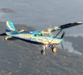
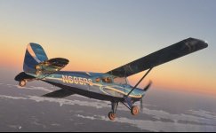
Kevin here are three photos taken minutes apart during sunrise first flight. Paint is loaded with metal flake and changes color with the amount of light.
 

Attachments

  • IMG_9313.png
    IMG_9313.png
    2.7 MB · Views: 23
  • IMG_4228.jpeg
    IMG_4228.jpeg
    142.6 KB · Views: 24
  • IMG_4227.jpeg
    IMG_4227.jpeg
    80.6 KB · Views: 23
Thank you!! Tires are 7’s. What specifically would you like photos of from the outside? The wheel pants or what other parts would be helpful? Would be glad to. There is a photos link that Jared took at Sun N Fun and some i posted after finishing the fuselage. But more than happy to take more.
It’s so very interesting to see a Bearhawk with smaller wheels and pants. Like you, I want a high wing traveler like a modern take on the high wing executive planes from the 30s. I’m not at all a stol/backcountry person. I would love more beauty shots of the plane with pants.
 
0
I will compile a description and photos and share those.
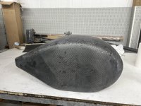
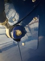
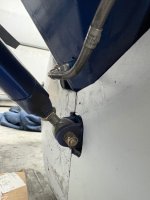
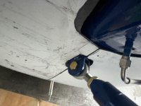
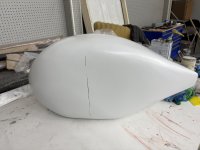
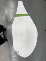
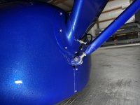
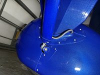
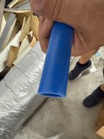
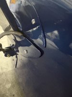
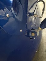
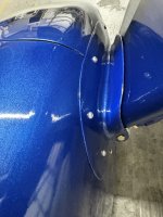
Steps: Pick a shape you like. I used the RV10 wheel pant shape as a starting point. Sketch the shape onto poster board and cut it out. Transfer to a block of foam (I just glued cheap blocks of styrofoam together). Carved with an electric turkey carving knife to the approximate shape then sanded to the final shape. I covered all the foam with drywall spackling and sanded then repeated that til no foam was showing. I sprayed it with a couple layers of epoxy primer and sanded that and did any needed touch ups primed again. Sanded it with 400/600 grit, and then waxed it with mold release wax. Covered with a good coating of. PVA mold release. Covered with 4 layers of carbon fiber. The shape is too complex for a single sheet of carbon to conform to without butchering, but you can probably do it with 2 overlapping sheets per layer. Just stagger your overlaps to avoids a big hump. After it cured I sanded it, clened it and covered it with epoxy micro to fill the weave and smooth the overlaps. I sanded that and touched up as necessary and then slathered with glazing/spot putty to fill all the pinholes in the micro. Sanded that then sprayed 3 coats of primer and sanded to a smooth 600 grit finish. You now have a mold for the second wheel pant. I waxed it and applied mold release liberally. I then repeated the above process putting the second wheel pant over the first one (dont be tempted to try to cut the wheel pant loose like this dumbass poster did). Noone will ever know that one is a few thousandths bigger than the other.. When the second wheel pant is finished to the completed primer stage, draw a perimeter line through the high point of the wheel and cut them both in two at the same time. Free them from each other and the mold and clean up the insides. Then tape the matching front and back parts together on the outside so that you have an assembled wheel pant. On the inside surface scuff a couple inches of carbon on the nose side of the cut line and put a tape release on the front two inches of the cut line of the aft half of the pant.. The purpose of this is to build a flange to mount the two halves together, Cut four strips of carbon 3 inches wided and due a wet layup along the inside of wheel pant cut line with at least one inch of the three inches on the release tape so you form a flange at least one inch wide. Let it cure. You can look at my photos and see where I put screws/nutplates but satisfy yourself and locate them as you wish. Just use clecos to hold them together for fitting until after you get thm fitted to the gear leg. Its sort of slow process of making gradual cuts to fit the nose over the gear leg from the front and the aft end over the gear leg from the back. What I did is cut the front half so that is one on the gear leg enough that the center of the axle was in 5e center of the flange (I messed that up on one of them). You will build a support to hold the outboard flange supported by the axle. I just used plastic pipe that I split to go around the axle cotter pin and insert about 2.5 inches into the axle. I wrapped the outer end with a carbon fiber layup and put a rivnut in the end after it cured. It would later get match drilled using a hole finder and go right through the flange you made above. With the nose positioned, I repeated for the aft half of the pant til I could connect the two halves with clecos. At this point itslikely sloppy loose on the gear leg. I then made an angle bracket out of 2 inches by 1/16” aluminum angle seen in the pictures. I attached it to the lower shock strut bolt. I then positioned the wheel pant so it was aligned perfectly in all directions and match drilled and clecoed the wheel pant to the aluminum angle. At this point you can use the hole finder to drill the axle support as well These two supports help stabilize the wheel pant for the injstallation of the strongest support which a 6 layer layup you will do between wheel pant the gear leg. But First dismantle everything and put a tape or stretch wrap release around the gear leg going 4 inches above and below the contact points of the wheel pant to the axle, Also cover the inboard end of the wheel pant with release tape so that the 6 layer layup does not stick to the wheel pant, Once you have all the releases in place, reinstall the wheel pant and then due a 6 layer wet layup between the wheel pant and the gear leg. I had to make mine about 5 inches wide on the outboard side of the gear leg transitioning to 4 inches on the inboard because of my location that the brake line exits the gear leg, Do what you need to do, The objective is to have a strong support of the wheel pant to the gear leg. But it needs to be removable so you have to keep it split on the back end (see pictures). After this layup cures, match drill it to the wheel paint before you separate the two. At this point the bulk of the work is done, You need to disassemble and put nutplates in every hole you drilled in the pant and you need to trim and bodywork the 6 layer layup and paint it, the angle support, and the wheel pant. . I also installed an extra 4 layers x 3-4 inches of carbon around the gear leg hole perimeter on the inside eof the wheen pant to stiffen the ares of the nutplates and reinforce around the hole to give stiffness and limit wheel pant movement. At thiz point its just prettying things up and paint them for final assembly,

my apologies, i tend to be a doer and not a photo taker so i have no photos of my supports, just the final product, also only 10 files are allowed to be attaches so i will send again the rest of my photos.
 

Attachments

  • IMG_4290.jpeg
    IMG_4290.jpeg
    4.9 MB · Views: 16
  • IMG_4503.jpeg
    IMG_4503.jpeg
    2.3 MB · Views: 21
  • IMG_4310.jpeg
    IMG_4310.jpeg
    2.5 MB · Views: 19
  • IMG_4309.jpeg
    IMG_4309.jpeg
    2.4 MB · Views: 16
  • IMG_4287.jpeg
    IMG_4287.jpeg
    3.4 MB · Views: 18
  • IMG_4269.jpeg
    IMG_4269.jpeg
    1.8 MB · Views: 15
  • IMG_4266.jpeg
    IMG_4266.jpeg
    2.6 MB · Views: 13
  • IMG_4253.jpeg
    IMG_4253.jpeg
    2.4 MB · Views: 12
  • IMG_4244.jpeg
    IMG_4244.jpeg
    2.4 MB · Views: 13
  • IMG_4501.jpeg
    IMG_4501.jpeg
    1.2 MB · Views: 14
Last edited:
0

Steps: pick a shape you like. I used the RV10 wheel pant shape as a 0starting point. Sketch the shape onto poster board and cut it out. Transfer to a block of foam (I just glued cheap blocks of styrofoam together). Carved with an electric turkey carving knife to the approximate shape then sanded to the final shape. I covered all the foam with drywall spackling and sanded then repeated that til no foam was showing. I sprayed it with a couple layers of epoxy primer and sanded that and did any needed touch ups primed again. Sanded it with 400/600 grit, waxed it with mold release wax. Covered with a good coating of. PVA mold release. Covered with 4 layers of carbon fiber. It too complex for a sheet of carbon to conform two but you can probably do it with 2 overlapping sheets per layer. Just stgger your overlaps to avoids a big hump. After it cured I sanded it, clened it and covered it with epoxy micro to fill 5e weave and smooth the overlaps. I sanded that and touched up as necessary and then slathered with glazing/spot putty to fill all the pinholes in the micro. Sanded that then sprayed 3 coats of primer and sanded to a smooth 600 grit finish. This is the mold for the second wheel pant. I waxed it and applied mold release liberally. i the.n repeated the above process putting the second wheel pant over the first one (dont be tempted to try to cut the wheel pant loose like this dumbass poster did). Noone will ever know that one is a few thousandths bigger than the other.. When the second wheel pant is finished to the primer stage, draw a perimeter line through the high point of the wheel and cut them both in two at the same time. Free them from each other and the mold and clean up the insides. Then tape the matching parts together on the outside. On the inside scuff a couple inches of carbon on the nose side of the cut line and put a tape release on the after two inches of the cut line. The purpose of this is to build a flange to mount the two halves together, Cut four strips of carbon 3 inches wided and due a wet layup along the inside of wheel pant cut line with at least one inch of the three on 5e release tape so you form a flange at least one inch wide. You can look at my photos and see where I put screws/nutplatex but satisfy yourself and locate them as you wish. Just use clecos to hold them together for fitting until after you get thm fitted to the gear leg. Its sort of slow process of making gradual cuts to fit the nose over the gear leg from the front and the aft end over the gear leg from the back. What I did is cut the front half so that is one on the gear leg enough that the center of the axle was in 5e center of the flange (I messed that up on one of them). You will build a support to hold the outboard flange supported by the axle. I just used plastic pipe that I split to go around the axle cotter pin and insert about 2.5 inches into the axle. I wrapped the outer end wi5 carbon iber layup and put a rivnut in the end, It would later get match drilled using a hole finder and go right through the flange you made above. With the nose positioned I repeated for the aft end til I could connect the two halfes with clecos. At this point itslikely sloppy loose on the gear leg. I then made an angle bracket out of 2 inches into by 1/16” aluminum angle seen in the pictures. I attached it to the lower shock strut bolt. I then positioned the wheel pant so it was aligned perfectly in all directions and match drilled and clecoed the wheel pant to the aluminum angle. At this point you can use the hole finder to drill the axle support as well These two supports help stabilize the wheel pant for the injstallation of the strongest support which a 6 layer layup you will do between wheel pant the gear leg. But First dismantle everything and put a tape or stretch wrap release around the gear leg going 4 inches above and below the contact points of the wheel pant to the axle, Also cover the inboard end of the wheel pant with release tape so that the 6 layer layup does not stick to the wheel pant, Once you have all the releases in place reinstall the wheel pant and then due a 6 layer wet layup between the wheel pant and the gear leg. I had to make mine about 5 inches wide on the outboard side transitioning to 4 inches on the inboard because of my location that the brake line exits the gear leg, Do what you need to do, The objective is to have a strong support of the wheel pant to the gear leg.. But it needs to be removable so you have to keep it split on the back end (see pictures). After this layup cures, match drill it to the wheel paint.before you separate the two. At this point the bulk of the work is done, You need to put nutplates in every hole you drilled and you need to trim and bodywork the 6 layer layup and paint it and the angle support. I also installed an extra 4 layers x 3-4 inches of carbon around the gear leg hole perimeter on the inside eof the wheen pant to stiffen the ares of the nutplates and reinforce around the hole to give stiffness and limit wheel pant movement. At thiz point its just pretty things up and paint them for final assembly,

my apologies, i tend to be a doer and not a photo taker so i have no photos of my support fabs just the final product, also only 10 files are allowed to be attaches so i will send again the rest of my photos.
 

Attachments

  • IMG_4510.jpeg
    IMG_4510.jpeg
    4.7 MB · Views: 16
  • IMG_4508.jpeg
    IMG_4508.jpeg
    4.1 MB · Views: 17
  • IMG_4507.jpeg
    IMG_4507.jpeg
    2.5 MB · Views: 13
  • IMG_4506.jpeg
    IMG_4506.jpeg
    1.4 MB · Views: 14
  • IMG_4505.jpeg
    IMG_4505.jpeg
    2 MB · Views: 10
  • IMG_4504.jpeg
    IMG_4504.jpeg
    1.7 MB · Views: 13
  • IMG_4499.jpeg
    IMG_4499.jpeg
    8.3 MB · Views: 12
  • IMG_4484.jpeg
    IMG_4484.jpeg
    3.8 MB · Views: 11
  • IMG_4467.jpeg
    IMG_4467.jpeg
    1.3 MB · Views: 13
Back
Top