Drilling the Wings

Bcone1381

Finished Patrol
I am setting things up to drill my wings and I have a question specific to where the spar plates attach to the fuselage attach fittings....if things work out I will be drilling them in the next day or so.

I have the drill guides from Mark G., and inserts fabricated from .028 tubing that will allow the holes size to step up 1/16th of inch at a time. I thought a mounting a chuck on the end of a rod would work for a drill extension, but my chuck is too large and will conflict with the fuselage tubing. I need a chuck smaller than 1" in diameter. might not make them....??? I am about to check Menards for a drill extension....I think I will need to use the drills with a hex end on them. Is that what other are using? (I dont have enough tubing on hand to fabricate extended drill bits by inserting/spot welding the drill bits into long pieces of tubing like the build manual discusses.)

The build manual talks about leaving the final holes undersize by 1/64th then ream them up to final size? I like that idea. But I dont have a guide for the undersized drill bit. In other words, I have a drill guide for the 5/16" drill and the 3/8 drill bit to drill the final holes for the front and rear spar holes, but if I wanted to drill them undersize 1/64th of an inch then ream them to size how is that going to workout if my insert is not set up for that smaller drill?

Brooks
 
Last edited:
Brooks,

Went down the same path several months ago. I had a 1/2" chuck that I screwed onto a 1/2-20 threaded rod. It cleared all the tubing and other obstructions and allowed me to drill in steps up to the final size in both the front and rear struts. Remember that the drill bit adds several inches to the length of the drill rod and helps with side clearance. A 3/8"chuck would have been better but I didn't have one.

You are welcome to borrow my set up to try. Send me your mailing address.

John Ciolino
Patrol kit
 
You can get chucks with various back ends. Threaded, tapered, etc. In addition to the various thread sizes and standards, there are several different taper standards. I've purchased a few imported ones on ebay with good success.
 
Can you guys please post a few pictures, when you do the drilling, for us who are yet to go down that path.
Regards Peter
plans 4 place #1184
Australia
 
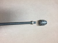
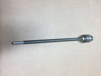
Attached are pics of what I used. Like I said I had a 1/2" chuck so I used that. A 3/8" chuck would be smaller around and mount on a 3/8-24 threaded rod. The 1/2- 20" and 3/8-24 are "odd" sizes which I could not find locally. I had to buy a 3 foot rod from McMasters-Carr for $9" plus shipping which was way more than I needed.

You can remove almost any chuck from a drill by opening the chuck and taking out the screw you find at the bottom. (I think it is a left had thread.) Them lock the chuck on a hex wrench and turn to get it off the drill shaft. Google chuck removal on YouTube.

I used the nut on the threaded rod to make removing the chuck easier. Just screw the check onto the the rod all the way, back off the chuck a turn or two and tighten the nut. To remove, unscrew the nut and unscrew the chuck by hand.

John
 

Attachments

  • photo4871.jpg
    photo4871.jpg
    958.4 KB · Views: 1
  • photo4872.jpg
    photo4872.jpg
    877 KB · Views: 1
If I were you, I would just read this.
http://www.bearhawkaircraft.com/asse...r-Fuselage.pdf

The only reason I am the expert is because I am a step ahead of some of you...at least for right now. It took me a day looking for drilling solutions, and at least a day messing around using a water level. That sentence is kind of an embarrassment to admit.

The things I did right so far...
- I like how I set up my fuselage...I built a fuselage stand using 2x4's attached to the fuselage engine mount bushing. This put the height of the wing attach points with the tail raised at about chest to shoulder level. A very nice working height.
-I made wing stands exactly like they are pictured in the attached pdf file. I had help getting the wings onto the stands. The stands are giving me the ability to work alone (bummer). Cant imagine doing this with a dry wall lift, or having a friend hold the wing. My advice....build four stands. Future Airport assembly with these stands will be a cinch.
-Finally, I like my water level, version 4 I think....maybe 5.

Things I did wrong
-soap in a water level may eliminate water surface tension but the bubbles create a worse problem.
-tugged on the water level...the hose connection (no hose clamp..didnt need one) let loose...water on the floor. Now its clamped with safety wire.
-Food Coloring in water does not help read the water level.
-tried 1/4" ID tubing, 3/8 is better.


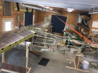
This is the big picture. Note tail stand and 3 of the 4 wings stands in view. Fuselage not on gear.
Click image for larger version  Name:	IMG_5221.JPG Views:	1 Size:	1.42 MB ID:	38564
The wing is loosely pinned with AN3 bolts. Note wing is not supported by inboard wing stand any more. You might be able to see my engine mount fuselage stand.
Click image for larger version  Name:	IMG_5222.JPG Views:	1 Size:	1.62 MB ID:	38565
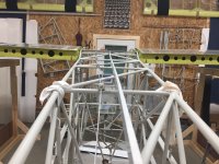
Another view.
Click image for larger version  Name:	IMG_5223.JPG Views:	1 Size:	1.45 MB ID:	38566

The first big step is pinning the wing to the fuselage with undersize bolts.
Click image for larger version  Name:	IMG_5227.JPG Views:	1 Size:	1.05 MB ID:	38567
This is a top view of the left front spar attach point, pinned with the 3/16" bolt. My Drilling plan A was to mount a drill chuck to a AN6 bolt, and weld it to a 14" rod.
NOTE:
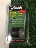
-the nose of the 3/8" keyless Jacobs Chuck 3/8"-24 threads for its mount. I forget the diameter of the chuck, (2 1/4" ??) but its touching the fuselage won't drill a hole where it needs to be.
-the clearance of.600" between the fuselage and the center of the mounting hole.
-the fit of the spar plates to the fuselage attach point....I cleaned some high spots of weld bead in the corners and the sides of the fuselage fitting. A 3/16" round file made by Stihl for chain saw sharpening (buy a three pack) has come in so handy time and time again. I used one to get into the corners. I did not touch the aluminum wing spar plates. I thought I might have to, and Bob approved slight rounding of the edges.
Click image for larger version  Name:	IMG_5229.JPG Views:	1 Size:	1.02 MB ID:	38568
Brand New unused drill chuck for sale.
Click image for larger version  Name:	IMG_5228.JPG Views:	1 Size:	1.63 MB ID:	38569
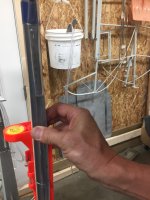
This is my water level, version 3 or four. The bucket hanging on the wall is my reservoir. 1/4" plastic line is cheaper than 3/8" but its a bit tougher to read and takes longer to settle down. The bucket side of the hose is attached to a piece of AL angle, I think I have 30' of hose. The Water Level's "user end" of the tubing is attached a stick. The tubing is infront of a metric scale thats also attached to the stick.. The bubble "post" level (used for installing fence posts plumb) allows me to hold my stick straight up and down. Before I attached the level, I was getting inconsistent readings due to the stick not being plumb to the ground. I don't see how one can get accurate readings without the post level.

Note, the water level is just above my thumb. To take a measurement I place the top of the "stick" in its desired position under the wing with the tip touching the skin, wait for the water to stop bouncing up and down, and read the level on the metric scale. For instance, I take measurements by placing the stick on a rivet that is coincident with the wing root, and the main spar to see where its at, then compare it with either the other wing root to check to see that they are level with each other, or the wing tip to set dihedral.
Click image for larger version  Name:	IMG_5231.JPG Views:	1 Size:	1.38 MB ID:	38570
Up close. Looks like 151mm. I am able to read to .5mm using reading glasses.

Realize....I have not yet drilled anything. Tomorrow I will be setting the angle of incidence. Hopefully my 12" drill bits will arrive from Aircraft Tool Supply.
Click image for larger version  Name:	IMG_5232.JPG Views:	1 Size:	983.2 KB ID:	38571
 
Last edited:
Having the fuse off the gear has been real nice for me too so far. I have it on jack stands each side at STA F, this lets me raise the nose to its 3 point attitude which has been useful as I’ve started routing fuel lines.
 
I used what I could find locally, I got an 18" 3/16 bit and for the 1/4, 5/16 and 3/8, I used the bits with the hex end and about a 12" extension that they fit into. Thats a nice set up, being able to put the wings on indoors. I had to take mine outside in my back yard and had my 80 year old neighbor help me. It was a long day but we got it done in one day. With it on the gear and on grass, I checked for level, and all measurements again before each time I drilled. On jack stands on a hard floor things are less likely to move. As I recall, mine never mover though, but it was worth checking each time since there is no going back.

By the way my neighbor is 82 now and not doing well and when I coordinated with his wife to bring him outside with his O2 tank that he now needs, so he could see me fly over and circle his house a few times, his reaction was much bigger than I would have expected. He really didn't think he would live long enough to see my Patrol fly and he told me that was one of the main things that was keeping him going. You just never know how big an impact you have on people.
 
You neighbor and his story spoke to me Rollie. There are a number of neighbors and acquaintances that keep asking me how its going. They take a genuine interest. Maybe I should be asking for more help from them rather than doing so much of it by myself.....make the build inclusive by nature rather than exclusive.
 
"-the fit of the spar plates to the fuselage attach point....I cleaned some high spots of weld bead in the corners and the sides of the fuselage fitting. A 3/16" round file made by Stihl for chain saw sharpening (buy a three pack) has come in so handy time and time again. I used one to get into the corners."

Thats a pretty critical attach point - and I'm just asking cause I'm NOT mechanical engineer - but wouldn't filing away part of the weld weaken that weld point?
 
Last edited:
Too Late. it was completed a few weeks ago. When the high weld spots impeded the spar plates from sliding in to place, something had to be modified. Bob B. and Mark G. were consulted.

These aircraft fuselages are hand made, not a high volume automotive type machine factory atmosphere. Outstanding quality. But this is a tight area, and in my case an adjustment was required. No material was removed from the fitting or from the spar plates...just a bump from the weld bead. Strength that the designer intended for this area was not compromised.
 
I started drilling the fuselage wing attach fittings a little while ago. I have read, and reread the kit builders manual on hanging the wings. It sure seems there a lot of different variables to get the holes to all line up, and be in line for and aft.

In particular I don't like the idea of drilling the forward holes in the spar, "on the bench". It seems to me that any imperfection in the squareness of the fuselage fittings will cause misalignment.

Here is what I am thinking about doing, but not sure yet. Drill the outside holes in the wing attach(front of the front, rear of the rear fitting) to final size. Don't drill the inside fittings yet. Using the Avipro drill guide, with the inside guide bushed down a size, drill the spar and then the inner wing attachment in one operation. Anybody tried this?
 
So wings are in position, dihedral and sweep set, holes centered. concentric and linear. Incidence as close to perfect as I can get it. I am not in a hurry. Drill undersize and ream? Kit Builder manual says not required. But probably "better".

Thoughts.? Experience?
 
So wings are in position, dihedral and sweep set, holes centered. concentric and linear. Incidence as close to perfect as I can get it. I am not in a hurry. Drill undersize and ream? Kit Builder manual says not required. But probably "better".

Thoughts.? Experience?

I like to drill 1/64 under and ream to size, I think you get a more consistent hole that way, less chance that the hole will end up slightly oversize. I had a 3/8th reamer but a EAA chapter friend loaned me a .373 reamer, the bolts fit nice and snug.
 
Last edited:
I am a bit cautious to do that in this case. It is a very thick hole, maybe about an inch. I don't have any way to guide a 23/64 bit, and the chance of getting off course through 2 pieces of steel and 1 big hunk of aluminum kind of concerns me. I really don't want to rely on my skill with a drill. I want to set up brain dead way to drill it that I can't screw up.

Did you fab up some type of guide for the bit?
 
By all means, get the drill guides from Mark , there is one each for front and back fitting, and the 7 page instruction pdf. I drilled in 1/16th increments from the original 3/16" holes. I went a step further and machined some stepped plugs to center and anchor the back side of the drill guides in the hole so I didn't have to worry about it moving while I was drilling.
 
I have requested from the factory a couple sets of the drill guides with some of the incremental size bushings required to step up to the final size. But will not have these for a few weeks. Mark
 
Mark, that would work great. My inability to do that myself is why I didn't drill undersize and ream. My holes are very accurate for location, but I think I would change one thing to make them better holes.
I do have tool marks inside my holes in the aluminum. I wish, in hindsight, that I had drilled as far as I could, removed the drill motor, sprayed WD 40, and pushed the drill bit out the other side. I believe the drill marks were made removing the bit, not drilling the holes. That was one thing I did not foresee. The drilling was very smooth. Removal a bit rougher.

BTW, I did have to do some extremely minor straightening in the fuselage fittings to get them concentric. Very little. After that, mounting the wings with 3/16:" rod, bushing them with tubing to pin them to the center of the holes, here is what I measured (dozens of times).

Incidence probably within 1/2 degree or less. I couldn't measure any difference. Water level, digital level, bubble level.

Sweep, within 1/4" (tolerance is 2")

Height of bottom of spar, again immeasurable with a water level. Actually multiple water levels.

Really good quality control. Made the job drilling easy. Well, as easy as it can get.
 
Back
Top