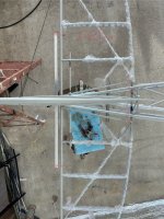
Horizontal Stabilizer Rear Spar Tube

Nrtabor5

Member
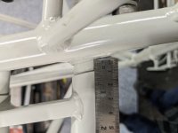
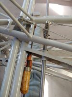
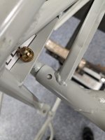
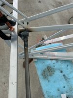
With the horizontal stabilizer mounted, leveled, and the lower stabilizer strut installed, the stabilizers are still too wide for the elevators to mount to the bearings. I can pull the stabilizer tighter to the fuselage but once i release the pressure, it slides back out. The gap between the rear stabilizer spar and the attachment bracket when pulled tight is 3/16", when I let it go it falls back to 11/32". This 5/32" of travel is causing the elevator to contact on the outer edges prior to seating on the bearings.

I've tried extending the lower stabilizer strut but it runs out of threads before it holds things securely. I did confirm the labels to make sure I hadn't mixed up left vs right stabilizer. Swapped it was even worse and the drilled holes on the front spars don't match. Also the drilled holes for the front spars seem to match the detail & dimensions shown on Drawing #21.

Do I need to install the tail wire's prior to mounting the elevators? I would go this route but it didn't appear that anyone else has them in place in any of the reference videos I've checked and the manual only references the strut.
 

Attachments

  • photo13633.jpg
    photo13633.jpg
    1.9 MB · Views: 6
  • photo13634.jpg
    photo13634.jpg
    1.9 MB · Views: 6
Alignment is important, you are picking up on key items.

Have not built a Model 5 tail but the 4 place method is as follows.

Attach the front horizontal attach tube with the correct angle of incidence from the CL of the aft horizontal spar tube to the CL of the front tube.
Place all the horizontal tail pieces on, in place, loosley.
Attach the Front Stabilizer Struts.
Pin the elevator hinges to the horizontal.
Attach the flying wires.
Bolt the elevator halves together. ( sometimes it is necessary to have a spacer between the two control horns of .032 ish.)
Pin the leading edge of the horizontal through the drilled pilot holes. ( .062 welding rod )
Slowly start taking up the slack in the wires and adjusting the tail surfaces.
The rear spar of the horizontal tail must have no Anhedral or Dihedral, no forward or aft sweep.
The leading edge must stay level, with no warp twist, adjust the forward strut.
Constantly checking level and squareness as the wires are tightened and the front strut is adjusted.
Check frequently that the elevators move freely with no binding.
Generally I find that a ring spacer of initial 1/8 in is needed at the place where you show the gap of concern.
Then fine tune by adjusting this spacer so there is no elevator hinge binding as the flying wires are tightened.
Check frequently that the elevators move freely with no binding.
As you move the elevator to full up and down limit, observe and make sure that the horizontal tail rear spar tube is not, " pumping up and down. "
Constantly checking level and squareness as the wires are tightened and the front strut is adjusted.
Rinse and repeat until all is true and free, then check alignment and drill the leading edge -3 bolts to size.
Record the thickness of the shims on the rear spar so when you lose the shim you do not have to do all this from scratch again........
The correct ring shim thickness is the result of good alignment,

That is what Original BH involves, the 5 might be slightly different.

Hope this helps.

Kevin D
#272
KCHD
 
From the pictures it looks like the horizontal stablizer rear spar tube is not being pulled in all the way up snug against the mount tube. You say when pulled up tight there is a gap of 3/16". The tube should pull up tight against the mount. (see the pic) I use a small bar clamp to pull things into place. If you are having trouble getting the tube to slide up all the way, perhaps there is some paint build up the needs to be dealt with. Also, be sure the the leading edge tube of the stabilzer is slid on all the way so the predrilled bolt holes match. Also, there really is no way to install the flying wires at this point, as the bolt that holds the wire attach tangs also goes through the elevator hinge. In other words, the elevator hinge/ flying wire tang all have to be assembled together. Collin

Stab fit.jpg
 
So I removed the front bolts and the support struts and the stabilizers have no trouble coming flush at the rear spar. In this position though the predrilled holes at the front spar do not align. The drilled hole in the stabilizer is only 11/16ths off the stabilizer bracket, page 21 scales to about an inch. I can pull the front spar away from the fuselage, into position for the holes to align, but that feels like a lot of tension in the stabilizer.
Should I pull the predrilled holes into alignment with the clamp in place and just continue the rest of the tail structure? Once the fly wires are in place I can remove the clamp? Or do I need to redrill the front spar holes so they are in their natural position with the rear spar flush?
 

Attachments

  • PXL_20230218_185014846.jpg
    PXL_20230218_185014846.jpg
    1.5 MB · Views: 3
  • PXL_20230218_185029456.jpg
    PXL_20230218_185029456.jpg
    1.8 MB · Views: 3
Some tension is normal, at least that is what I have been finding. You definitely don't want to redrill the holes in the front spar, that would change the alignment of the rear spars. You could remove the clamp after the wires are installed, but I usually don't install them until later...your choice. Main thing is to keep the rear spars tight as you proceed to make up the trim torque tube assembly.
 
What did you end up doing on this? I am installing the tail feathers and have the exact same issue on my model 5.
Travis
 
I ended up following Collin's advice and clamping the stabilizers together whenever they're on. Until it's ready for flying wires this has worked out fine and I have noticed similar clamps across a wide range of other builds. This is one of those "trust the process" things that I figure will be easier to troubleshoot later (if there are problems) if I follow the experienced advice now.
 
How is the front spar carry-through labeled? Is there a right and left? If not, maybe unbolt it and flip it 180 degrees and see if that makes a difference. Just a thought...
 
I’m just putting my horizontal stab on now. My mount tube was labeled left, up and front and right, up and front. Only two could ce correct at any time. If I had it left/right the up/down was correct but the fwd was aft. The two horizontal stabs fit this way so I’m keeping it like that.
 
My horizontal stab also did not fit properly onto the bearings. after a lot of measuring, i found the entire horizontal stab was racked due to the rear spar stub not being perpendicular to the fuselage. after discussing with Bob, we decided to heat and bend the stubs to bring hem into alignment. that worked well but i did have to redrill the front spar stub attachment points. it all fits well now.

IMG_0646.jpg IMG_0642.jpg IMG_0652.jpg
 
Dealing with same mislabling issue on my Companion QB. Maybe something lost in translation.
Have-Purple,

First, legendary name... not sure if its a Lockheed reference or not but that's awesome! Second, I have the same issue on mine that I am getting ready to release in a video in the next few weeks. I have an impossible combination of left right up down and back. I went with the 2/3 that agreed with each other and got lucky. How is your elevator attachment going? I just now sorted how the companion does it because it is starkly different than the 5's and other models apparently.

CM
 
I had the same issue on my 4, maybe it’ll get a closer look on new kits?
Mine is assembled, but just barely and very tight. I was thinking about a little heat to relieve the stress on the front, but now I’m going to check for the alignment issue aborite had. Thanks for bringing this old thread back up.
 
Back
Top