LSA140 Build

lsa140

Plans Built Bearhawk LSA
I appreciate the ideas, experience, and resources that the Bearhawk community shares with each other. I will be posting my experience building the LSA in this thread, and hope fellow builders find it enjoyable and useful.

The fuselage will be constructed using the Bearhawk tubing kit.

Build Table:
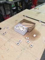
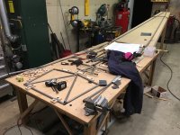
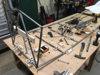
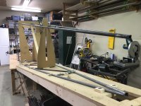
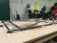
I already have a 4'x8' table available from a previous project. I didn't want to take up shop space with another full size table at this time, so I decided to build a tapered extension table for the fuselage build. It is constructed using two full length 10' 2x4s. The wide end is 3' and the skinny end is 1'. The top of the fuselage will be tacked together with the extension table flush with the 4'x8' table. Once this is completed the tapered extension will be set on the end of the 4'x8' table and angled to match the bottom longeron up sweep. The bottom fuselage tubing will be assembled in blocks, but not tacked - to allow adjustment as the side tubes are added. (thanks BTAZ) Internal plywood top fuselage supports will then be added one at a time and the vertical fuselage centerline will be marked using a laser. The tacked top fuselage tubing will be centered on the support marks, secured, and fine tuned. The connecting tubes and diagonals will then be assembled and tacked.

The tapered table should allow good access for assembly and tacking. The internal supports will give unobstructed access to assemble the fuselage tubing.

I built the tapered table this afternoon and will be fine tuning the combination tomorrow. I hope to receive the tubing kit early February and will be brushing up the welding skills until if arrives.

LSA140
 

Attachments

  • photo1935.jpg
    photo1935.jpg
    441.3 KB · Views: 0
  • photo1936.jpg
    photo1936.jpg
    497 KB · Views: 0
  • photo1937.png
    photo1937.png
    432.3 KB · Views: 0
  • photo1938.png
    photo1938.png
    521.8 KB · Views: 0
  • photo1939.png
    photo1939.png
    598.9 KB · Views: 0
Last edited:
While waiting, you might want to make a bunch of blocks to screw to the tables to hold the tube in position. Perhaps 1x1" and a few larger or of varying shapes, maybe 30 total or so.

If you are going to wait to tack the bottom like I suggested, you will want it well blocked into position.

The planned plywood verticals are different and probably would work but I would think it would be easier to just clamp 2x4's of the appropriate length to your table legs as verticals and then clamp 2x4's as horizontals to support the top frame.

The tubing fits together incredibly well so you want your jig to easily adjust to the tubing fit. Not sure the plywood verticals will allow this..
 
Great input BTAZ, I appreciate the thoughts. I'll run by HD today and pick up some material for blocks. Previously I have used 1x2 pine with undersized pilot holes and 1-2 screws depending on the location. I would leave the screws in the blocks and move them around as needed. The soft wood worked well for squeezing against the tubing and screwing to the table.

I will make sure to secure the bottom tubing well. I am glad to hear things fit snuggly. Having previously built a fuselage from strait tubing, I appreciate the good value of the pre notched kit. I think you mention in your log as well that building with a notched tubing kit the jig needs to fit the tubing, not the other way around. Being able to firmly secure things, but move them around seems to be the way to go. Tighter gaps make welding easier, especially with .028 wall.

The 2x4 method looks like a good and established way to suspend the upper fuselage. I may end up using it when the time comes, or a combination of the two. On a previous build I used the plywood and was pleased with the results, but it was constructed by tacking the sides on the table (rather than the top and bottom).

I see you suspended the upper fuselage in three locations, did that work well? It looks like the furthest forward support was just behind the rear spar carry through. Did that provide enough stability around the cockpit?
 
To support the top, I clamped the verticals both to the table and to the rafters. Three sets because that's how many rafters I could clamp to and not block the garage door opener.

The trickiest part was getting the various tubes in the firewall area in place all at the same time to be tacked. I think the firewall itself could be built flat(I didn't) but jigging it to the rest of the fuselage took some creative jigging and clamping.

I used left over MDF scraps for my blocks but I think pine would have been better because it doesn't give off noxious fumes when you scorch it while welding.

Use wood that smells nice burning......

Still, definitely can't complain about having a tacked fuselage after just a couple weekends.
 
That is definitely great progress for a couple weekends. I'm impressed by how much you have accomplished in a couple years of work. I was wondering about the firewall area. I ordered the Continental engine mount from Mark to help align and locate the mount bushings on the fuselage rather than trying to adjust factory mount later to fit my fuselage. I was wondering if I could tack the firewall area flat on the table and then jig at the proper angle in relation to the rest of the fuselage. Maybe even clamp the firewall tubes flat in some type of plywood jig and then mount that to the table. It looks like all the firewall tubing is all 5/8", it might be simple to jig that area up together. Did the engine mount bushings that get welded to the fuselage come with the tubing kit? It looks like a couple of them get sandwiched between the lower firewall corners and diagonals.

I have some scrap cedar around, that would make for some good aroma...
 
I don't remember about the bushings but the tubing is notched for them.

I knew I would be building my mount(this weekends project) so wasn't as concerned about exact bushing placement. If I was buying the mount, I would probably wait on the bushings until I had the mount.

With the bushings, make sure they extend far enough on both ends that you don't melt them. My bottom ones were just a little too short on the inside so took some creative work to square the ends so the engine mount bolt head/nut would sit flat when installed.

I can't remember where I saw it, but after I had done mine I saw that the firewall could be tacked flat(like I did the gear truss) and then put in place. Might even be in the LSA book that came with the plans.
 
Those bushings look like a challenge to weld. I will make sure to leave them long enough. I've seen other designs put small corner gussets on either side of the firewall tubing at each mount location. The front and rear gussets are then drilled to the bushing OD. The gussets weld to the firewall tubing, and the bushings insert through the gussets and are welded front and rear. It looks a little cleaner, but adds to the weight and part count.

It looks like the LSA book mentions tacking the firewall frame on page 39.

I ended up taking my table height down this evening after realizing it would put the tail post through the ceiling sheetrock, and the upper tubing more difficult to reach. My existing table was 36", and I planned on using it as is, but things are easier to work on with a 30" table height. Everything will clear with 9' ceilings.

The tables were leveled quickly using shims and a self leveling cross line laser. I highly recommend one of these tools. I purchased one a number of years ago for a boat building project, and use it frequently. It will be mounted several feet in front of the table on the fuselage center line, shooting through the firewall and towards the tail.

http://www.amazon.com/DEWALT-DW088K..._UL160_SR160,160_&refRID=1FFG1ZGWWAX5KGMCHDSS
 
I too had ceiling height limitations so used a truncated tail post through most of the build until it was time to add the vertical stab.


Side benefit is it makes the fuselage much easier to rotate during the welding process.
 
I went back to your build log, and saw the short, temporary tail post you used for assembly alignment and left tacked place for rotisserie welding. It looks like you left it place until vertical stab construction, fit the full length tail post to the tail spring socket, assembled the tail on a bench, welded, and then aligned - welded the entire assembly to the fuselage? That seems like a good way to go, were you pleased with the results? Your post reminded me of doing something similar on a previous fuselage. The tail post was not used as an alignment reference on that design, and I left it off until after welding the fuselage. After the tail post was welded on the fuselage was a lot more awkward to move around.
 
No Title

Laid out the tubing centerlines for both the top and bottom fuselage sections.

I decided to go with oversized holes and small fender washers for the tubing blocks to allow easy adjustment to accommodate the pre notched tubing. The blocks are pine 1x2 with a half inch hole. 1-5/8" Gold screws, and 1/8" x1" fender washers. This setup allows the blocks to move side to side a max of 5/16".

Constructed internal fuselage jigs to support the tacked upper tubing. The front support captures station N cross tube and the rear support captures station L cross tube. The setup allows easy vertical adjustment. The supports are hinged at the table and an adjustable diagonal provides fore and aft movement while holding center. Now that everything is built, I will pull it off the table until I'm ready to assemble the upper and lower fuselage halves.

Started brushing up the TIG welding skills, and working on torch setup.
 

Attachments

  • photo1971.jpg
    photo1971.jpg
    312.9 KB · Views: 1
  • photo1972.jpg
    photo1972.jpg
    527.8 KB · Views: 1
  • photo1974.jpg
    photo1974.jpg
    647.4 KB · Views: 1
  • photo1973.jpg
    photo1973.jpg
    639.7 KB · Views: 1
No Title

All ready for the tubing kit. Set up a fence and drilled all of the block holes together. Used stop in the chop saw to quickly cut everything to length. Most of the blocks are 2" long with a few 4" and 6".

I enjoyed watching this video Bearhawk Aircraft posted of jigging/tacking a lower fuselage section, placing it in the main fuselage jig, and putting the bends in the lower longerons:
https://www.youtube.com/watch?v=-HhqY90kKXM

Played around with paint schemes last night. Will likely go with some variation on red, grey, and deep charcoal.
 

Attachments

  • photo1995.jpg
    photo1995.jpg
    528.8 KB · Views: 0
  • photo1996.jpg
    photo1996.jpg
    572.1 KB · Views: 0
  • photo1997.png
    photo1997.png
    224 KB · Views: 0
Last edited:
Looking forward to seeing it go together!

I just finished my last large weldment today(the engine mount) and was basically where you were about seven months ago(except I already had the landing gear struts and the tail feathers done) so I can pretty confidently say that if you follow the plans all will work out.

However, it is still a large welded assembly so once the main frame is assembled, everything else needs to be built to fit it with plans dimensions more as a "guide" then the rule.
 
Thanks BTAZ, its good to hear you where able to finish up your engine mount. Are you going with a small Continental? I look forward to seeing more BLSAs in the air.
 
In the beginning, I toyed with using an 0-320 but Bob talked me out of it.

I have a C-90 project engine that I am planning on using.
 
No Title

On a previous project I gas welded 4130 with the Meco Midget torch and ultra light weight hoses. I have some training and experience with both TIG and gas. I would echo Bob's recommendation to utilize gas welding, for the reasons he stated in his build manual. For this project I will be going with TIG, because I enjoy the process and am confident it will produce an airworthy product.

I have a Miller Diversion 165 TIG and have converted the torch to a CK FL1325SF FlexLoc with a 25' SuperFlex lead. Installing this torch required removing the cover of the welder, and installing an adapter from Arc-Zone. USA Weld sells a nice metal foot pedal that plugs into the RJ45 connector used on the Diversion. I am currently experimenting with different torch setups, and enjoy using CKs pyrex cups/gas lenses.

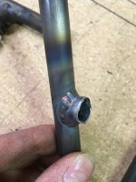
I conducted some informal testing to better my understanding on how heat impacts thin wall 4130 tubing. The tubing used is USA 1/2"x.035 4130. Both samples were welded with ER70s-2 filler rod. The shop was just bellow 60 degrees. I wanted to observe how the colder air temps impacted the tubing.

(see attached photos)

The sample on the left was preheated to 400-500 degrees, TIG welded, and immediately brought up to around 1600 degrees with a gas torch. I slowly pulled the flame away and let the tubing cool in still air. This sample (pre and post heat) bent back and forth in a 20 deg arch around 10 times before any cracking appeared. I was very impressed with how tenacious the heated sample was.

The sample on the right was TIG welded with no preheat, and left to cool in still air. This sample (no pre or post heating) bent to around 10 deg and cracked abruptly.

This is a very informal test, but it does illustrate the impact heat can have on 4130 tubing. I am in no position to make welding recommendations (other than agreeing with the designer). This is simply one of the steps I took to better inform my own approach to welding.
 

Attachments

  • photo2002.jpg
    photo2002.jpg
    627.7 KB · Views: 0
  • photo2003.jpg
    photo2003.jpg
    648 KB · Views: 0
  • photo2004.jpg
    photo2004.jpg
    348.1 KB · Views: 0
Last edited:
I hear that. The climb would be incredible with that much power, light weight, lower drag, and high aspect ratio wings. It would likely take it right up against the 140mph VNE?
 
This is a very informal test, but it does illustrate the impact heat can have on 4130 tubing. Again, I am in no position to make welding recommendations (other than agreeing with the designer). This is simply one of the steps I took to better inform my own approach to welding.

Wow, that's pretty dramatic -- my welds don't look as good as yours, but I've beat the *&%&$ out of `em... When my shop is below about 55-deg, I'll preheat my test welds with propane, now I'm not so sure... early on I had the weld fail, but maybe I'm not pushing the tubing enough for the failure your getting... I like TIG, but I'm just a weekend hack and sometimes I just grab O/A for the comfort...
 
My observation is that both TIG and gas produce quality welds that will hold beyond the surrounding metal. They do however impact the surrounding tubing differently because of how each process applies heat. Understanding and controlling heat is a big part of any metal fabrication, and even more so when it comes to lightweight aircraft components.
 
No Title

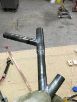
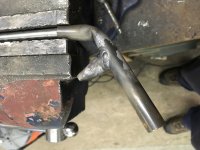
More welding practice/informal testing this evening. I tested one sample, using the same 1/2x035 tubing, with 400 deg preheat and no post heat. It held longer and bent further than the non pre/post heated sample, and broke in a perfect fish mouth contour just off the weld.

After testing a few more samples I realized that I may be taking the tubing slightly towards the annealed condition with my some of my post heating. It was bending easier than a piece of non-welded normalized 4130. The tubing would wrinkle in several spots under load, and I could bend it back and forth nearly a dozen times without cracking. I don't think it is necessarily a bad thing to have the tubing near the clusters a little softer. A little ways up the tube and out of the HAZ it remains in its normalized state. (how it arrives from the factory)

It is interesting to note that an annealed piece of 4130 tubing is still quite a bit stronger than a piece of 1025 that you find in some Piper fuselages.

I'll order a high temp IR gun from Amazon this evening to check my post heating temperatures. I'm hoping that if the post heat is dropped to 1200 deg and allowed to air cool the results will be better. The vast majority of the fuselage joints would never incur this type of loading (except in a crash). One of the only ones that comes to mind is where the axle tube welds to the gear legs.
 

Attachments

  • photo2029.jpg
    photo2029.jpg
    235.2 KB · Views: 0
  • photo2030.jpg
    photo2030.jpg
    345 KB · Views: 0
  • photo2032.jpg
    photo2032.jpg
    239 KB · Views: 0
  • photo2033.jpg
    photo2033.jpg
    214.2 KB · Views: 0
  • photo2034.jpg
    photo2034.jpg
    343.1 KB · Views: 0
  • photo2031.jpg
    photo2031.jpg
    344.3 KB · Views: 0
  • photo2035.jpg
    photo2035.jpg
    219.7 KB · Views: 0
  • photo2036.jpg
    photo2036.jpg
    245.1 KB · Views: 0
Last edited:
There is endless debate on pre and post heating 4130 online in various forums. I came across a thread that was getting a little "heated", and someone tried to lighten the mood with the following stress relieving method:

[FONT=arial, helvetica, sans-serif]"I have used this process quite a few times with mixed results. First I start with some gangsta rap with the deep bass hits (NWA or Snoop Doog works well) and I use at least a pair of 15" subwoofers, then after about 30 minutes I alternate to some heavy metal such as Pantera or Metalica. For an extra bit of treatment you can step it up to Slayer or Seplutura, but only for 4340 and 300M. Last but not least finish with Kenny G to slowly bring it back to sane tempature, but too much Kenny G. will make the weldment weak and spineless, and lower the tensile strength."[/FONT]

[FONT=arial, helvetica, sans-serif]It had me laughing hard enough that it got my wife's interest, and I had to try to explain welding humor... Time to throw out the torch and break out the Pantera. [/FONT]
 
Great to see someone else doing some weld testing; I did similar testing. The fuselage (4 place) I bought was welded with TIG and I have continued to weld on the fittings with TIG only because I am much better with the TIG than I am with O/A. Once I complete the welding and it is warmer here I will stress relieve most of the clusters. Nothing like a tailpost failure to make you rethink the welding process...

IMG_1298 by Jon Whee, on Flickr
 
Last edited:
Garage door catch it? Better to find that weak point during building than flying... Some tail surfaces shake pretty hard under high power settings on tube and fabric aircraft, though the Bearhawk has another measure of bracing with the rigid horizontal stab strut. Watch the tail during takeoff on some of the high horsepower cubs, or when they drop the tailwheel; the surfaces shake quite a bit.
 
I believe concave welds put the surface in tension as it cools and can lead to cracking in the weld, or where the toe of the weld meets the base material. I've been working on adding enough filler to form a strait, or slightly convex surface shape on welds. This shape also increases the ratio of ER70s-2 filler to 4130 in the weld and contributes to a more ductile weld. The smaller concave weld also cools at a more rapid rate due to having less mass, which can lead to more brittleness in the weld. I could see where a large, hot, concave puddle could put quite a bit of stress on the weld and tubing as it cools.
 
Last edited:
I haven't seen one, you could try starting a new topic in the LSA plans built forum to see if anyone else has.
 
No Title

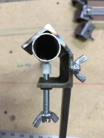
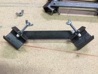
Made a set of four tubing clamps this afternoon. I used some 1"x1"x1/8" angle and 1/8" flat bar that was on hand. The hardware is 1/4-20. I had a left over bag of rubbermaid shelving end caps that make nice little pads on the end of the clamping bolt. Max capacity using these materials is 1", though you have to pull off the caps to back the bolts that far. 3/4" (shown) slips in nicely.
 

Attachments

  • photo2053.jpg
    photo2053.jpg
    158.4 KB · Views: 0
  • photo2054.jpg
    photo2054.jpg
    225.5 KB · Views: 0
  • photo2055.jpg
    photo2055.jpg
    333 KB · Views: 0
  • photo2056.jpg
    photo2056.jpg
    378.9 KB · Views: 0
I don't plan on putting the LSA on floats until several years after the plane is flying, but I want to put provisions on the fuselage during construction rather than cutting into the fabric down the road. Bob mentions in a video interview on youtube that he wouldn't see a problem putting the LSA on floats from a design standpoint, but other than that I haven't seen anything discussing floats for the LSA. It doesn't look like many Bearhawks of any type have been put on floats. https://youtu.be/mwenTHwJs00?t=5m56s

There is discussion in the Patrol forum on which station the rear float strut would attach to (D or E). http://bearhawkforums.com/forum/bear...ting-locations Looking at the LSA, station E is around 10-12" further aft than the Patrol due to there being fewer stations aft of the rear door post. (which places more spacing in between the rear stations on the LSA)

I roughly scaled a set of Zenith 1450 Amphib floats, and very roughly placed them under the LSA. It looks to me that placing a rear float attach fitting at station E on the LSA would result in a very steeply angled rear float strut. At first glance stations B-D (45-1/2" apart - Cubs are around 43") seem like a possible option to attach floats to the LSA. I'm curious if anyone has discussed this with Bob?

Patrol%20floats_zps7lwipmjw.PNG
 
Last edited:
No Title

Picked up the tubing package this afternoon. The shipping company had cracked the PVC shipping tube in several places, but overall it arrived in good shape. No tubing appears to be damaged. A big thank you to Mark Goldberg for his quick email responses, and help. I'm sure he answers the same questions a thousand times, and he does so kindly.

I loaded everything into the tubing rack except the top fuselage tubing. The tubing kit comes wrapped in several groups that correspond well to the build process. Top, Bottom, Left Side, Right Side, etc. I jigged the top tubing upside down, this allows the change in transition that occurs in the top longerons (when viewing from the side) to lift slightly off the table. Looking both at a 3d drawing based off of the plans, and how the tubing set in the blocks, this puts the furthest forward top cross tube (P) centerline right around 1" above the table. The rest of the tubing lays flat on the table surface. This will make more sense with some pictures tomorrow.

The longerons are coated with a thick yellow paint from the factory for QC purposes. As Mark points out, and others are following, the areas around the clusters can be cleaned for welding and the remaining paint blasted off when the fuselage is being prepped for paint. With welding, and torch post heat, an area 8-10" either side of the cluster would need to be stripped of paint to avoid burning paint fumes. Stations being around 36" apart, this would mean stripping 16-20" of that distance, so I just decided to remove all of the paint. The area around the cabin will receive various tabs/etc welded to the longerons, and I would rather be rid of the paint than pulling out the acetone every time to clear a small area.

All the best.
 

Attachments

  • photo2070.jpg
    photo2070.jpg
    833.3 KB · Views: 1
  • photo2071.jpg
    photo2071.jpg
    471.4 KB · Views: 1
  • photo2072.jpg
    photo2072.jpg
    389.9 KB · Views: 1
  • photo2073.jpg
    photo2073.jpg
    507.7 KB · Views: 1
Last edited:
Although I remain largely silent, I admire your work, and will probably copy a lot of your ideas for my shop. I attended EAA Sportair Welding Workshop just last month in Oshkosh. The O2/Acet welding rig is now set up in the Garage and I have been practicing on warmer days in Michigan. The examples of Tables, clamps, fittings, etc that you pass along give me ample opportunity to practice making practical stuff before I will ever get to making a real airplane part.
 
It is great to have a community of builders to exchange ideas with, I'm glad you are finding some useful things to incorporate into your shop and project. Some of these tools that we fabricate to build our aircraft, are very enjoyable projects in themselves. Best of luck on the welding practice and project.
 
No Title

Tacked the upper fuselage tubing together and pulled it out of the blocks this evening. Much of the afternoon was spent cleaning the tubing of paint and oil. I removed all of the tubing labels once their location was established. A 50/50 mix of acetone/lacquer thinner and a mild abrasive pot scrubber work well for paint removal. 320 emery cloth was used to remove scale from each joint area and denatured alcohol to wipe down.

Overall the tubing fit was decent. I felt that some of the diagonals were a little on the loose side. With the cross tubes placed precisely on plan layout/square and the longerons tight against them, a few of the diagonals in the tail section had a bit of play. I shifted things around best I could to accommodate, and split the play on either end. The gaps are acceptable, but there. 028 is a much bigger challenge to weld with gaps than 035, at least for me.

Assembling the top tubing upside down worked out well. Make sure you rotate the longerons to get the bend angles headed in the right direction. The tubing blocks with the oversize hole and fender washers are the way to go on a pre cut tubing kit. It really allows you to shift things around easily, highly recommended.

My wife picked me up this little ruler for my birthday, and it is awesome. Get one. Slip it in your breast pocket, and it is always on hand. I used it constantly today to check how the tubing matched the perimeter layout marks. Also, these magnetic vice jaw inserts are great for tubing. Both items are off of Amazon, and are worth every penny.
 

Attachments

  • photo2082.jpg
    photo2082.jpg
    465 KB · Views: 1
  • photo2083.jpg
    photo2083.jpg
    603.3 KB · Views: 1
  • photo2081.jpg
    photo2081.jpg
    611.2 KB · Views: 1
  • photo2085.jpg
    photo2085.jpg
    395.1 KB · Views: 1
  • photo2087.jpg
    photo2087.jpg
    566.8 KB · Views: 1
Last edited:
I've been terrified of bringing my O/A welding gear into the basement, lest I blow up the house. I've heard it's fine, but I'm not sure I'm falling for it just yet...
 
I hear that, I always try to stop welding 1/2 hour before leaving the shop just to make shure nothing is smoldering.
 
No Title

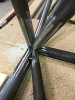
Unwrapped the rest of the tubing today. Stripped that white paint off of the lower longerons, glad to be done with that. Tacked the firewall together. Assembled it with the front facing down to allow proper alignment of the lower joints. (It is a rather complex joint.) I used some 1/2 tube to leave the proper clearance for the engine mount bushings. A short piece of 3/4 x 035 was cut that mirrored the end of longeron to make sure all the merging tubes lined up. I think it is put together right, we will see tomorrow. I'm starting to get used to building from the tubing kit. As others have said, is a little backwards of what is familiar. I had the firewall drawn out, but the kit tubes where off from plans a little. There was a little moment of debate on making the tubes fit the template, but then I realized I just needed to roll with the kit. Variations are to be expected.

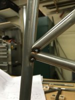
I've been using the TIG to tack everything, it takes longer but results in nice strong little tacks that are easy to weld over. It also provides a little more practice. Stitching the ends of some of those small tubes down in a joint is rather dedicate, but it is getting easier.

Separated the rear tapered table, and placed it in position to block up the lower fuselage. The laser continues to come in handy for quick alignment. Tacked the gear truss up, but left the outer diagonals off until mating it with the rest of the fuselage.
 

Attachments

  • photo2088.jpg
    photo2088.jpg
    461.2 KB · Views: 1
  • photo2089.jpg
    photo2089.jpg
    569.7 KB · Views: 1
  • photo2090.jpg
    photo2090.jpg
    608 KB · Views: 1
  • photo2091.jpg
    photo2091.jpg
    614.8 KB · Views: 1
  • photo2092.jpg
    photo2092.jpg
    633.4 KB · Views: 1
  • photo2093.jpg
    photo2093.jpg
    525.3 KB · Views: 1
  • photo2094.jpg
    photo2094.jpg
    577 KB · Views: 1
No Title

Got the bottom tubing all aligned, and firmly blocked in place. 3/32" holes used sparingly in the longerons under joints to allow passage of air and prevent weld blowout. The fit of the lower tubing was excellent. I'm planning on float attach fittings at station D. Looking over PA-18 plans, 1"x049 is used at that similar location. (where the cub attaches the rear float strut.) Other tubing sizes in that general area are very similar to a cub. The LSA calls for 7/8"x035. I had some extra 7/8x049 on hand, so I got out the tubing notcher and swapped out for the thicker wall. The two vertical internal jig supports hinge at the table. Moving the diagonal on the front support allows for fore and aft movement of the tacked top fuselage tubing. Tomorrow I have a large stack of side tubing to clean and prep before jigging in place.
 

Attachments

  • photo2099.jpg
    photo2099.jpg
    572 KB · Views: 1
  • photo2100.jpg
    photo2100.jpg
    558.3 KB · Views: 1
  • photo2101.jpg
    photo2101.jpg
    556.2 KB · Views: 1
  • photo2102.jpg
    photo2102.jpg
    518 KB · Views: 1
  • photo2103.jpg
    photo2103.jpg
    499.2 KB · Views: 1
  • photo2104.jpg
    photo2104.jpg
    538.9 KB · Views: 1
  • photo2105.jpg
    photo2105.jpg
    412.5 KB · Views: 1
  • photo2106.jpg
    photo2106.jpg
    482.1 KB · Views: 1
  • photo2107.jpg
    photo2107.jpg
    519.9 KB · Views: 1
Last edited:
Looks great! After cutting and fitting tubing for my scratch build 4-place its nice to see it coming together so quickly!
 
Thanks Wayne, much appreciated. Tubing kits are a great value, and a kick to build. Best of luck on you LSA project.
 
No Title

Most of the fuselage tubing in place and tacked today. There are several more tubes to go in around the firewall/cockpit and some overheard structure around the wing attach area. It is nice to see the stack of tubing shrinking. Small pieces of aluminum foil tape work great to temporarily secure tubing at cluster locations. The wire feed came in handy for one hand tacking. Spent most of yesterday cleaning and prepping the remaining tubing. I noticed on a previous project that sometimes a small amount of oil rests just inside the tubing ends. Once in a while it can cause contamination in the weld. I filled a small container with about 3" of acetone, and dipped each end repeatedly/wiped down with a rag. The acetone ended up brown from the grit and oils, and the tubing ends came out clean. My cross line laser is mounted several feet in front of the fuselage, shooting a horizontal and vertical line at fuselage C/L. It has been handy for checking alignment.
 

Attachments

  • photo2121.jpg
    photo2121.jpg
    351.2 KB · Views: 1
  • photo2122.jpg
    photo2122.jpg
    585.8 KB · Views: 1
  • photo2123.jpg
    photo2123.jpg
    493.9 KB · Views: 1
  • photo2124.jpg
    photo2124.jpg
    351.2 KB · Views: 1
  • photo2125.jpg
    photo2125.jpg
    589.1 KB · Views: 1
  • photo2126.jpg
    photo2126.jpg
    628.6 KB · Views: 1
  • photo2127.jpg
    photo2127.jpg
    334 KB · Views: 1
  • photo2128.jpg
    photo2128.jpg
    382.9 KB · Views: 1
  • photo2129.jpg
    photo2129.jpg
    485.6 KB · Views: 1
  • photo2130.jpg
    photo2130.jpg
    666.9 KB · Views: 1
  • photo2131.jpg
    photo2131.jpg
    451.5 KB · Views: 1
  • photo2132.jpg
    photo2132.jpg
    355.6 KB · Views: 1
Last edited:
Your attention to detail, fabrication innovations and progress, are commendable! Don't for a minute suspect that I'm discounting any of that. But I'm absolutely impressed with the pre-cut tubing! Are the tube ends cut on a CNC high def plasma or laser system? A customer, of mine, had a Trumpf Tubematic that could spit out the most amazing tubing fitments that I'd ever seen. It would make sense for Mark to employ such a system, but it took an awful lot of volume, to justify that equipment, at the time. If Mark is reading this, how are the tube cuts made? I spent 40 years, around metal fabrication and this impresses me!

Bill
 
Thanks for the encouraging words Bill. I believe each piece of tubing has its own steel marking fixture, see the video bellow. Is this still how the factory notches the tubing ​Mark Goldberg?
https://www.youtube.com/watch?v=SQZKVPMwPNc

One of the major reasons I chose to go with the Bearhawk is their approach to offering many different paths to aircraft completion. It supports and honors the spirit of the homebuilding community. Many companies (understandably) withhold selling plans, and only offer kits.

I previously built a tubing fuselage from scratch, and knew right away the value a tubing kit would bring to the project.
 
Last edited:
Well, now I'm even more impressed. They cut and finish each of those tubes manually! That explains why they fit the tubes into a jig.
This is what I was talking about; https://m.youtube.com/watch?v=azaJsnbbH9c
That thing would spit out each tube, perfectly cut, in about 10 minutes, if that. But then, it takes a bunch of volume, to pay for these beasts!

Bill
 
No Title

Only a few pieces of tubing left in the stack. I still need to tack on a temp tail post and put on a few more tubes in the tail, but other than that everything is tacked.
 

Attachments

  • photo2137.jpg
    photo2137.jpg
    468.5 KB · Views: 1
  • photo2138.jpg
    photo2138.jpg
    405.7 KB · Views: 1
  • photo2139.jpg
    photo2139.jpg
    611.3 KB · Views: 1
  • photo2140.jpg
    photo2140.jpg
    551.7 KB · Views: 1
  • photo2141.jpg
    photo2141.jpg
    409.8 KB · Views: 1
  • photo2142.jpg
    photo2142.jpg
    408.2 KB · Views: 1
  • photo2143.jpg
    photo2143.jpg
    356.9 KB · Views: 1
  • photo2144.jpg
    photo2144.jpg
    434 KB · Views: 1
No Title

*Note: Deviation from plans. Changes to the LSA shown here have not been approved by the designer. I will be making a few modifications to the cockpit area for my specific mission. One of those changes is to the rear seat. From the stock position it will be adjustable: 4-5" forward, 2" lower - 2" higher, the seat base incline will adjust, and the seat back recline angle. The seat will not span the entire width of the rear fuselage. The frame will be around 19" wide. I need to be able to remove, fold, and stow it in the baggage area. Additional structure will be added from station B to D. (similar to the changes incorporated into the Patrol in 2014, in this same area.) The aircraft will be used extensively off airport. The purpose of these mods will be to strengthen the gear and float attach areas, as well as increase the cockpits ability to resist deformation in a crash. A very close eye is being kept on retaining the light weight of the LSA. The photos bellow show a truss that I designed and tacked together today. It serves a multiple roles: 1. Strengthen the float attach area. 2. Provide more rigidity and support to the 3/4"x 035 tube that runs vertically to the rear wing spar attach. 3. Provide an attach point for two vertically adjustable seat supports. 4. Provide a tie down point and barrier to keep cargo strapped down and away from the rear stick when the passenger seat is out. I made and drilled two telescoping seat supports, jigged, and tack welded them to station D. The bottom portion of these will be removed when the welding is finished on the rest of the truss. I cut most of the way through, half way up the supports. This will allow easy removal later. The jig was removed, and the remaining truss tubes were fitted and tacked. I also found a tapered 3/8 nozzle online, with a tapered contact tip for my little 135 welder. It works great, and makes getting into clusters for tacking much easier.
 

Attachments

  • photo2146.jpg
    photo2146.jpg
    624.4 KB · Views: 1
  • photo2147.jpg
    photo2147.jpg
    581.1 KB · Views: 1
  • photo2148.jpg
    photo2148.jpg
    597.6 KB · Views: 1
  • photo2149.jpg
    photo2149.jpg
    454.8 KB · Views: 1
  • photo2150.jpg
    photo2150.jpg
    461.5 KB · Views: 1
  • photo2151.jpg
    photo2151.jpg
    493.7 KB · Views: 1
Last edited:
I want my wife to be sitting as high as the overhead clearance allows and comfortable. I also need to be able to drop the seat all the way to the floor for someone my height. No need for a fancy panel or interior, but the seats need to be just right.
 
No Title

*Note: Deviation from plans. Changes to the LSA shown here have not been approved by the designer.

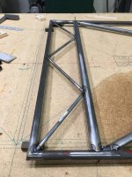
Cut and assembled the additional side cabin truss assembly. The diagonal tube that runs across opposite the door has been omitted. (it was cut up and used for the truss) The diagonal in the side truss runs opposite of the Patrol, which I believe would be more ideal, but I want to utilize as much of the original LSA tubing kit as possible.

Some small pieces of plated where added, sandwiching the seat adjustment tube socket. I wanted a little more structure to carry loads through that area than just a short piece of tubing with holes. With some good welds, the area should be sufficient for its purpose.

Approximate weight gain:
Station D truss: 1.25 lbs
Cabin side truss: 1.25 lbs (almost half of the tubing came from the omitted diagonal)

There will likely be additional weight added with the adjustable seats and dual doors, though I am considering some ways to keep those items very light.
 

Attachments

  • photo2153.jpg
    photo2153.jpg
    598.9 KB · Views: 0
  • photo2154.jpg
    photo2154.jpg
    631.4 KB · Views: 0
  • photo2155.jpg
    photo2155.jpg
    337.9 KB · Views: 0
Excuse my question, but I feel the need to ask; have you done some testing, of TIG welding over your MIG tacks? I can't state, without some reservation, that I recall problems with such, but I absolutely recall problems involving MIG fill passes, over some specific SMAW tacks. The problems were caused by high levels of de-oxidizers, in the stick electrode, not being well tolerated by the MIG fillermetal. Granted, this was a fairly specific application, but one that was puzzling and unexpected. Be sure to 'qualify' your specific TIG process (including your specific fillermetal), over your specific MIG tack process.
The last thing I want to do, is unecessarily stir up a mess. But I don't want to ignore something that could present an issue.

Bill
 
Chris In Marshfield
​I prefer tacking with TIG, but trying to bend over and reach across the build table through a tubing maze at difficult angles to place a little tack gets old quick. If I was going for a perfect looking final weld I would slow down and strictly use TIG for tacking, but my goal is a balance between production and quality. Everything will be TIG welded once on the rotisserie. .023 wire with a 3/8 nozzle on a small gun seems to work well on the wire feed. I have a little 110v Northern Industrial 135 wire feed that I paid $165 new. Wrestling a large gun with 035 wire would be a disaster, getting setup specifically for tacking is worth the effort.
 
Thanks for the tip. I have a Hobart 140 (similar class of machine). I plan to torch weld mine. But the quick-attach of the MIG will certainly go faster (and cooler).
 
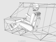
This afternoon as I was cleaning up around the shop I got distracted by the tacked fuselage sitting nicely on the table and started thinking through cockpit layout. Pretty soon I was sitting on blocks and trying the pilot and passenger positions on for size. As I sat in the front seat, I realized there was a large volume of space above the rudder pedals, and under the instrument panel. This evening I pulled up some build photos of another LSA with the boot cowl off/instruments installed, and sure enough there is quite a bit of free space. (even with the instruments/etc installed.)

Playing around in CAD, I came up with this forward fuselage storage box. It would not be accessible in flight, and there would be a latch on either side to insure the door would not have any chance of coming open at the wrong time and interfering the pilots legs or controls. It would be TIG welded out of aluminum and hang from several tabs welded to the airframe. The door would face the pilot and hinge down against a stop, resting parallel to the bottom of the storage box.

It would be lined with some light weight padding or carpet to keep contents from rattling around with the engine vibration. Depending on your CG, you could utilize the space for small heavy items, possible tools and survival items. I could see a tool wrap, pistol, etc. Lighter survival items would be tucked away in the rear baggage (sleeping bag, tarp, etc)

The usable space would be around 27" wide, 6" tall, and 12" deep. Plenty of room would be left for legs and feet. You could possibly leave the two front upper corner cut out to be able to inspect the upper engine mount bolts, or leave it back far enough to lay under the panel and look up in front of the box. It would be easy enough to remove as well.

Screen%20Shot%202016-02-19%20at%2010.53.01%20PM_zpsyrsri4jv.PNG
 
Last edited:
Certainly a nice place for logs, maps, manuals, and other things used between flights. Cool and creative use of space!

Off topic, what are you using for CAD? I'm getting started with Autodesk Inventor to document my project.
 
Thanks Chris. I use and highly recommend http://moi3d.com and http://www.rhino3d.com. Think of MOI as a 3d sketchbook, it is by far my favorite piece of software. The two programs use the same native file type (3dm). Ideas take shape in MOI and Rhino has more powerful CAD functions, plugins, and complimentary programs.
 
No Title

Finished final tacking the fuselage this afternoon. Put in a short temporary tail post, the full length tail post will go in after the rest of the frame is welded and off the rotisserie. I have a two month job at a remote site starting this week, and am having a hard time putting the project down. There is building, and there is funding the build... both are required. It will be a good opportunity to finish designing the seats and cockpit layout.

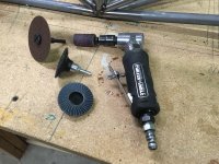
I've been really pleased with this little Porter Cable PTX2 die grinder. A 1/16" x 3" cut off wheel comes in handy for cutting or grinding tacks. The little 3/4" sanding drum worked well for fine tuning the tail post fit. The 2" fine scotchbrite spin on wheels work great for cleaning tubing ends. The 2" flapper grinding disk removes material quickly. For most standard garage fab projects a 4" electric grinder is the go to tool, for aircraft work this little die grinder is the ticket. I wish I had purchased one sooner.
 

Attachments

  • photo2159.jpg
    photo2159.jpg
    816 KB · Views: 1
  • photo2160.jpg
    photo2160.jpg
    524.8 KB · Views: 1
  • photo2161.jpg
    photo2161.jpg
    656.6 KB · Views: 1
  • photo2162.jpg
    photo2162.jpg
    337.7 KB · Views: 1
  • photo2163.jpg
    photo2163.jpg
    483.3 KB · Views: 1
Looking great!! Keep up the good work. I can relate to taking time off the build. I have a roof project kicking off in a couple weeks. The tubing kit went together quick and it is addictive watching the rapid progress.
 
Thanks Stephen! I'm appreciative to you and BTAZ for posting your build experiences. It helped me decide on purchasing the tubing kit, and how to go about putting it together. I hope you project is coming along well, and the roof goes quick.
 
I've been out of town working long shifts, and haven't been able to physically work on the plane. It has provided an opportunity to research and plan for upcoming purchases/work.

Here is what the LSA looks like on 27.5" Desser Aero Classic Tundra Tires, and the Bearhawk Tundra Tailwheel.

Screen%20Shot%202016-03-21%20at%205.50.09%20PM_zpsi7f7e1mf.PNG
 
Last edited:
No Title

*Note: Deviation from plans. Changes to the LSA shown here have not been approved by the designer.

Some tubing aft of station G-K had been previously been left out. (diagonals and tail spring socket tubing/supports) I hadn't yet decided what type of tail spring I was going to install. After some thought, I've decided to go with the LSA/Patrol round tapered tail spring. The tubing kit came with 1 x 058 socket and 1-1/8 x 049 outer reinforcement tube. There was a little slop in the fit. I'd prefer the reinforcement tube to rest directly against the socket tube. A scrap piece of 1-1/8 x 058 fit snug around the socket, so I cut out a new piece and welded the two tubes. This also gives me a little more metal to support the spring and retaining bolt. I believe the Patrol uses the thicker 058 reinforcement tube as well.

I have a temporary short tail post in place until rotisserie welding is finished. I won't be tacking all of the tubing around the tail spring mount at one time. Some pieces will be welded together on the bench, others will be tacked on at a time and fully welded. That area has some difficult places to reach with all of the tubes in place.

Here is the high temp infrared gun I found on amazon. It reads up over 2,000 degrees and was a little under $100. I haven't used it much yet, but look forward getting some time with it.

http://www.amazon.com/Taotuo-Non-co...dp/B00PEHCYBW?ie=UTF8&psc=1&redirect=true&amp ;ref_=oh_aui_detailpage_o02_s00
 

Attachments

  • photo2326.jpg
    photo2326.jpg
    408.1 KB · Views: 0
  • photo2327.jpg
    photo2327.jpg
    487.2 KB · Views: 0
No Title

*Note: Deviation from plans. Changes to the LSA shown here have not been approved by the designer.

Decided to attach the full length tail post to make welding that area easier. Adding one tube at a time and stopping to fully weld everything possible before placing the next tube. The tail area has some tight spaces, and this method is making it easier to get good welds.

Preheating with a propane torch to around 300-400 degrees. Bumped the wall thickness of the tail post to 049. This is absolutely not needed, I just wanted a little more metal in that area for my specific mission. I've added around 12 ounces of weight to the tail. The tundra tailwheel is a little heavier as well. This will help offset the extra 20lbs+ of bush tires up front.

I beveled the bottom edge of the tail post, exposing the 3/4 liner. I'll use a very sharp tip on the TIG electrode and walk in a nice full bead to fuse everything together. I preheated the tail post/liner and used the wire feed for the rosette welds. I much prefer the TIG for most applications, but once in a while a circumstance comes up that the MIG is well suited for. The Northern Industrial 135 welder I bought years back runs smooth at a very low heat setting/wire speed. The 3/8" nozzle with tapered tips are coming in very handy.
 

Attachments

  • photo2330.jpg
    photo2330.jpg
    370.1 KB · Views: 1
  • photo2331.jpg
    photo2331.jpg
    379.6 KB · Views: 1
  • photo2332.jpg
    photo2332.jpg
    378.7 KB · Views: 1
  • photo2333.jpg
    photo2333.jpg
    408.5 KB · Views: 1
  • photo2334.jpg
    photo2334.jpg
    413.1 KB · Views: 1
  • photo2335.jpg
    photo2335.jpg
    359.7 KB · Views: 1
  • photo2336.jpg
    photo2336.jpg
    369.6 KB · Views: 1
Last edited:
No Title

Continued to add tubes, and weld up the tail spring attach cluster. Even with adding one tube at a time and welding, those inside corners are really difficult to weld! It made me wish I had one of the tiny low clearance specialty TIG torches.

The remaining tube that runs from the front of the sprint socket to the tail post needs to be tacked and welded.
 

Attachments

  • photo2340.jpg
    photo2340.jpg
    345.6 KB · Views: 0
  • photo2341.jpg
    photo2341.jpg
    347 KB · Views: 0
  • photo2342.jpg
    photo2342.jpg
    302.4 KB · Views: 0
Thanks man, much appreciated. I've been dreaming of doing this for many years, its enjoyable to share the process.
 
No Title

I switched from a gas lens setup to a standard #5 cup with a short back cap for the tight spaces. 1/16" sharp tungsten. I was expecting oxidized welds with such a small cup, and very limited electrode extension. Surprisingly, the welds were coming out silver, and I was able to get quite a bit of electrode protrusion for the tight corners.

Added the last piece of tubing to the tail spring attach area, and welded it. Time to build a rotisserie.
 

Attachments

  • photo2343.jpg
    photo2343.jpg
    333.5 KB · Views: 0
  • photo2344.jpg
    photo2344.jpg
    334.8 KB · Views: 0
Last edited:
I have a C-85 in my C140, and it's got some gumption! Also flew a local PA-11 with a C-90 in it. Amazing how nice they are.
 
No Title

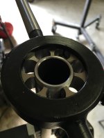
Finished up the tail side of the rotisserie. The multiple telescoping tubes provides a long range of adjustment. I picked up a couple 1/2" barrel nuts and built my own u-joints. I need some additional washers and bolts to final assemble the joint. For now I will be grabbing onto the tail post with some u-bolts covered in rubber tubing. Later in the process a 7/8" piece of tubing will slide into the tail spring socket and mount to the u-joint plate.
 

Attachments

  • photo2384.jpg
    photo2384.jpg
    345.6 KB · Views: 0
  • photo2385.jpg
    photo2385.jpg
    397.6 KB · Views: 0
  • photo2386.jpg
    photo2386.jpg
    489.4 KB · Views: 0
  • photo2387.jpg
    photo2387.jpg
    523 KB · Views: 0
Thanks! I thought about going to the wrecking yard or buying a steering shaft with a couple u-joints. If it was going to be used in a production shop, that would have been the best route. It was enjoyable to figure out how to build some with standard hardware and materials.
 
No Title

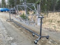
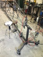
The fuselage mounted on the finished rotisserie. The small scaffolding casters lock in roll and rotate. It rolls across small lips and gravel easily. A set bolt on either end locks the fuselage in rotation. Time for some welding.
 

Attachments

  • photo2391.jpg
    photo2391.jpg
    538.6 KB · Views: 1
  • photo2392.jpg
    photo2392.jpg
    757.1 KB · Views: 1
  • photo2393.jpg
    photo2393.jpg
    814.1 KB · Views: 1
No Title

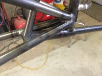
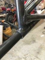
Welded the tail post, and continued working forward. I was reminded again how much more difficult 028 is to weld. Especially when welding to thicker wall tubing. In theory you keep more of your heat on the thicker tube, and let the puddle wick over into the thinner tube. Easy to do sitting at a table, a whole different challenge when attempting gymnastics to reach a weld cluster on a fuselage. The pulsing box I purchased for my Diversion TIG really helped tackle the 028 tubing. I don't feel like it is needed on 035, but it really helps with the thinner wall.

I'm dealing with residual oil inside some of the tubing. It is left over from the manufacturing process. It slowly worked its way down several of the vertical side tubes and covered the lower clusters. I finish weld the upper cluster at a station, then use a fine stainless wire brush dipped in acetone to clean up with tacks/oil. Also, grinding down the tacks help them assimilate into the weld.

Preheat with a trigger start propane torch, on a 12' hose, attached to a 20lb propane tank. It works well, and is easier to move around than a torch with a bottle attached.

I had to adjust my welding after getting used to 035. It works well to keep the weld beads a little narrower. Use plenty of filler, its easy to undercut 028, and that is the last thing you want on such a thin piece of tubing.

I was getting very frustrated after a couple hours of dealing with oil, thin tubing, and trying to get in a good positions to weld the tight tail area. Took some deep breaths, enjoyed some spring air outside, and came back to it with a little more patience. This is really challenging, but very enjoyable.
 

Attachments

  • photo2408.jpg
    photo2408.jpg
    598.4 KB · Views: 0
  • photo2409.jpg
    photo2409.jpg
    342.5 KB · Views: 0
  • photo2410.jpg
    photo2410.jpg
    390 KB · Views: 0
  • photo2411.jpg
    photo2411.jpg
    404.7 KB · Views: 0
  • photo2412.jpg
    photo2412.jpg
    312 KB · Views: 0
  • photo2413.jpg
    photo2413.jpg
    442.2 KB · Views: 0
  • photo2414.jpg
    photo2414.jpg
    329 KB · Views: 0
  • photo2415.jpg
    photo2415.jpg
    385.3 KB · Views: 0
  • photo2416.jpg
    photo2416.jpg
    458.3 KB · Views: 0
Last edited:
Thanks Chris, and to you as well. It's been great to be able to follow allow with your wing build. I'm ready to take a fresh go at it this morning. I find some time away from the project in the evening helps bring what needs to happen next into better focus.
 
I really enjoy reading your posts and looking at the pictures.
Have you weighed the fuselage? I'm curious how it compares to the cub types.
When I'm welding thin to thick, and the thin wants to try to burn away, I "build bridges" between the two pieces, i.e. Put a tack weld every 1/8" or so along the weld that your having trouble with. When you come back over its the final time, the tendency to burn away is greatly reduced. Seems to work for me, your mileage may vary.
 
Thats Clint, I haven't weighed the fuselage yet. Do you have a weight from your C-90 cub build? Comparing the tubing, the LSA and cub use very similar sizes/wall thickness. The LSA uses 3/4x028 upper longerons. I almost switched over to 035, but my tubing kit already had the 028 bent and notched. The bearhawk line has more structure above the cabin. There is an upper truss structure that runs from the rear baggage to the tubes that run down in front of the door/firewall. The rear fuselage is also full height, unlike the cub fuselage which tapers down behind the rear spar carry through and relies on formers to continue the fuselage shape back to the tail. I'm guess the LSA would be very close in weight, but possibly slightly heavier due to the extra tubing.

Thanks for the welding tip! The bridges would act as little heat sinks as well. I took a TIG welding course at the community college during high school, and hadn't picked one up for 18 years. I definitely feel my limited experience when going from welding in convenient positions to inside an airframe. Being able to see where my electrode is at, and what it is doing to the metal is a real challenge in some of those tight corners. Worked on refining my welding lense/glasses setup yesterday, we will see how things go today.
 
If I remember correctly, mine weighed 98 lbs and that was with some of the Alaska mods.
A friend of mine built a javron cub and powdercoated and stringers installed, it weighed 104 lbs.
I'm really surprised that people are still building Cubs with the stringer setup the way it is, as its really nothing more than an evolution of the Taylor E-2 which was practically a parasol. The top longeron like the bearhawk uses is much stronger and much easier to weld.
 
" I'm guess the LSA would be very close in weight, but possibly slightly heavier due to the extra tubing." At Oshkosh once Bob took me to see a bare Cub fuselage and commented how many more pieces of tubing the Cub had as opposed to the Patrol. I seem to recall 30% more individual pieces of
tubing on the Cub than the Patrol. So I was surprised to read your comment. Mark
 
That was just guess on the amount of tubing, I wouldn't doubt the actual part count is less. Do you have the weight of a factory LSA fuselage with paint? I'm actually really pleased with the structure, it seams very robust. Many other LSA tube and fabric designs use smaller tubing. The fact that Bob built his plane within 120 lbs or so of a Zenair 701 is amazing. They use thin aluminum, short wings, and a very light rotax engine. Very impressive.
 
Being patient with the 028 wall is worth it. Hard to tell the difference when you pick up a long length of 028 over a piece of 035 the same size but when you weigh a finished part that's when you realize the wt savings. Good looking work and progress. Having built all the Patrol weldments from scratch I know how hard you've worked.
 
I'll weigh my fuselage when it comes out of the rotisserie. It will still have a lot of fittings and structure to add, but it will be good to get a weight. I'm keeping close track of additional weight that has been added. I've always wondered why Piper built the supercub that way, didn't realize it was an evolution of a parasol design.
 
No Title

Finally got everything dialed in for welding the difficult to reach thinner tubing located at station G-K. As I move forward in the fuselage there is a lot more room to work. A big thank you to dedgemon for sharing the Servore auto darkening goggles from Amazon in one of his threads. http://amzn.com/B00LKWLSS0 I removed the ear pieces from my glasses, cut two small slits in the face gasket rubber, and slipped them into place. They stay put, and are far enough forward to not contact my face. The goggles with face mask are much easier to get into tight spaces, but dont flip up like a helment. I found that a very bright LED headland allows me to keep the goggles on, easily get in position, and inspect the weld without removing them. I have a lightweight head sock that seams to keep the arc from burning my face. The goggles are highly recommended. Once in a while tubes will block both light sensors, and you will get a mild flash. Again, this wont be an issue further forward in the fuselage.

I swapped out the #8 pyrex cup for a #6 ceramic cup using the same gas lense. This allowed for plenty of electrode extention, better clearance in tight joints, and the funneled shape of the cup provided better coverage with less gas flow for this type of welding.

A small stainless wire brush, dipped into a container of acetone, continues to work well to remove oil and contaminates. After it quickly evaporates, I hit the joint with a quick propane torch preheat.

The cluster shown bellow was covered in oil, but it cleaned up well with the method above, and welded nicely. I dealt with a little contamination, but it was doable. Being able to see well, having the right torch setup, and keeping the weld beads smaller/heat lower worked well for the 028. Welds should improve as I get some more time welding, and move forward into roomier parts of the fuselage.
 

Attachments

  • photo2428.jpg
    photo2428.jpg
    397.8 KB · Views: 0
  • photo2429.jpg
    photo2429.jpg
    344.4 KB · Views: 0
  • photo2430.jpg
    photo2430.jpg
    358.5 KB · Views: 0
  • photo2431.jpg
    photo2431.jpg
    275 KB · Views: 0
Last edited:
No Title

I recieved my axles from Aircraft Spruce, and the 1-1/4 x 16TPI threading die/handle from ebay on friday. I wasn't sure what kind of quality could be had on 4130 with a threading die, but it turned out very nice. A 1-1/4" was drilled in a small 2x4 and slide over the axle. I placed a spring clamp under the block to provide a little resistance, but still allow the block to slide down the axle as threading progressed. The block kept the die completely square for the initial thread cut. After the threads were started, and die traveling properly, I pushed the block down the axle. This allowed the chips to fall clear of the operation. I went slow, cleared often, and used plenty of cutting oil. The threads are very smooth. I'll do a little cleanup where the threads stop, cut the retaining pin slot, and polish things a little. You can see from the photo bellow how much finer the 16tpi over the 12tpi. I plan on getting a lathe down the road, but am trying to keep focused on building.
 

Attachments

  • photo2432.jpg
    photo2432.jpg
    680 KB · Views: 0
  • photo2433.jpg
    photo2433.jpg
    456.3 KB · Views: 0
  • photo2434.jpg
    photo2434.jpg
    278.8 KB · Views: 0
  • photo2435.jpg
    photo2435.jpg
    584.1 KB · Views: 0
Last edited:
I'm intrigued by TIG and the weld quality that can be achieved. Looking forward to seeing how your already good welds improve as you move up.

I'll be working with OA, most likely. But could be talked into TIG pretty easily,
 
Our booth is next to Vans Aircraft at OSH. The weight difference is not great between the all aluminum RV12 (with Rotax/short wings etc) compared to the BH LSA with steel tube structure and O200. MG
 
When I read of your plan to use a die, I wondered how you'd keep it square to the tube. Very crafty solution!

Bill
 
Well, I moved up, but I dont know if they improved... I mentioned it earlier in the thread, but I completely agree with the recommendation to use OA. For most people, that would be the best choice. That being said, I'm really enjoying the TIG. I'll be ready to weld a fuselage by the time I'm done with this one:)
 
No Title

Here is the setup I'm using for preheat. I've been warming up the clusters, and out each tube a short distance outwards.

The welding is going well. Finished through station F-L.
 

Attachments

  • photo2441.jpg
    photo2441.jpg
    647.9 KB · Views: 0
  • photo2442.jpg
    photo2442.jpg
    378.3 KB · Views: 0
  • photo2443.jpg
    photo2443.jpg
    387.3 KB · Views: 0
No Title

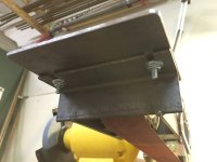
Here is what I came up with to grind a radius. Many parts on the Bearhawk have an outer radius centered on a hole. This modification to my folding grinder rest lets me quickly grind a very nice round edge. The rest surface can be adjusted with two slotted bolts to accomodate different radius. After the radius is ground, the rest is folded down, and the edge gets a quick dressing to get all of the grind marks running with the part, and a slight bevel put on the edge. The holes will be reamed to .190 for an AN3 bolt. This is a quick video demonstrating it in action: https://youtu.be/mTV_VlAlT0Q

I used some 3M Super 77 spray adhesive to lightly tack down a part template. It was cut out on the band saw, center punched, drilled, ground, and the template pealed off. A little acetone to remove the adhesive. It went quick, and worked well. I will be using this method for many of the flat parts.
 

Attachments

  • photo2444.jpg
    photo2444.jpg
    618.6 KB · Views: 0
  • photo2445.jpg
    photo2445.jpg
    379.2 KB · Views: 0
  • photo2446.jpg
    photo2446.jpg
    323.4 KB · Views: 0
  • photo2447.jpg
    photo2447.jpg
    449 KB · Views: 0
  • photo2448.jpg
    photo2448.jpg
    303.6 KB · Views: 0
Last edited:
Back
Top