LSA140 Build

No Title

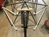
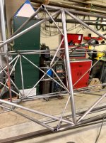
Starting to really enjoy welding the fuselage. I highly recommend the XL tig finger. I had ordered the smaller tig finger as well, but have not ended up using it for the fuselage. The XL slides nicely past your four fingers and works well to rest against the hot tubing.

Yesterday I tried out this large gas lens set from weldcity. The #10 tapers down to a workable size, and you can get very long electrode extension if needed. I've had it out further than shown in the image. The big lens and tapered cup seem to funnel a nice stream of gas. I also really like the ergonomics of gripping the cup. This lens and torch combination seem to work well for this application. It really pushed the gas into the odd shapes, angles, and corners encountered on welding the fuselage.

I've found that feeding the puddle from the rear works well on the tight elbow joints.
 

Attachments

  • photo2457.jpg
    photo2457.jpg
    433.4 KB · Views: 0
  • photo2458.jpg
    photo2458.jpg
    511.4 KB · Views: 0
  • photo2459.jpg
    photo2459.jpg
    331.6 KB · Views: 0
I tried out a KMG at the trade show portion of the street rod nationals last year. Makes me want one. Burr Kings are nice too. I've been getting by for the last 25 years on a Jet 6x48 and a 12" disc.
 
I almost picked one up last fall, but decided to invest the money into airplane parts. They have some interesting wheels/attachments for notching tubes.
 
No Title

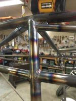
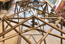
The large gas lens and long electrode extension came in very handy on this cluster... The top, right longeron (.028) at the rear of the baggage compartment has 7 tubes intersecting it. It took some body contorting, and patience to run all of the welds with the grain/fused nicely deep in the corners.

I'm seeing a small amount of contamination surface on the weld puddle on occasion, but haven't encountered anything disruptive. It's easy to end up with grinder crumbs and residue oil just inside the tubing fishmouth. Before assembly each tube end was dipped in acetone and wiped with a cloth, but a small amount held on in some tubes.
 

Attachments

  • photo2474.jpg
    photo2474.jpg
    371.8 KB · Views: 0
  • photo2475.jpg
    photo2475.jpg
    367.3 KB · Views: 0
Last edited:
Thanks Chris, I'm up where you will actually be able to see them when the plane is finished, trying to be on best behavior:)
 
No Title

Another cluster with 7 tubes interstecting the longeron. (one tube more than plans - additional structure added to this area) This on sits left side, behind the pilot. (station D) This is where I will be adding some float fittings. I'm trying to decide between standard (similiar to the gear attach) or flush (external mount that bolts into some bushings welded on the fuselage) The airplane is so clean, I hate add extra fittings hanging out in the airstream, but that might be the easiest way to go.
 

Attachments

  • photo2479.jpg
    photo2479.jpg
    345.5 KB · Views: 0
  • photo2480.jpg
    photo2480.jpg
    394.4 KB · Views: 0
Wow, that's a lot of tubes! Looks like the welder (both the machine and human) handled it with ease. I'll be putting my float fitting on the outside like standard gear attach. One of the Alaska builders did his that way as well. Check Paul Minelga's (alaskabearhawk) YouTube channel. He filmed a BH float attachment that's very informative.
 
On the next fuselage I will go ahead and tack everything with tig. They are very clean/low metal volume. It is quite easy to weld right over the top of a small tig tack. A larger wire feed tack with a little bit of oxidation on the weld surface disrupts a nice welding rhythm. I ground down everything I could reach, but I had some down in the corners that I had to just weld over. Those deep corners on the big clusters are difficult! Welding with the grain towards a deep corner, trying to contort your body to keep clear sight of the weld, and finding an angle to slip the filler rod into the puddle is a pain for sure. It would be hilarious to have photos of some of the postions you have to contort into while welding a fuselage.

One thing that has really helped is getting better at feeding the puddle from the rear. You can pause slightly, swell the puddle a little with filler, and move forward with the arc. You can see it getting excellent penetration into the two pieces of metal, and the swelled puddle wicks right into the two melted edges. I can see where being able to weld left handed would be handy. I do it once in a while on the fuselage, but it is very awkward.

I've been really impressed how well tig works filling minor gaps in joints, the tiny arc and precise heat control comes in very handy.

Thanks for the tip on Paul's video, I remember watching it a while back, but will pull it up again.
 
Those are some great looking welds!
At the risk of sustaining heavy flack, I'm going to throw out another welding consideration. There are LOTS of fuselages flying, that are completely MIG welded. While I wouldn't necessarily recommend such, I would like to see a pulse-MIG system used. The process is very close to TIG, in control and appearance, but easier since you don't have to orchestrate the torch & filler rod. The equipment isn't cheap, but the results are amazing!
>>>>INCOMING<<<< 😳
 
No fire fight from me! I imagine that there's a place for all welding technologies if everything is used within its designed limits. This coming from a guy who hasn't welded anything in his life except a few short pieces of mild steel plate and tubing in an EAA workshop. :-)
 
I'm pretty sure the forum rules need to reed: No politics, religion, or debating/arguing weld methods for 4130... All of the mentioned topics get heated fast. Pun intended:)
 
Unfortunately the Servore auto darkening goggles started flickering on and off, even in full view of the arc. I tried changing the batteries, and adjusting every possible setting. They worked great for a week, and then all of a sudden started having issues. I'm out of the tail section, and have more room to work, so these will be getting sent back.
 
No Title

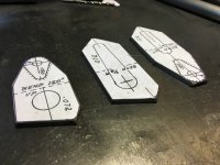
Worked on landing gear attach fittings this afternoon. Used a dead blow hammer and a 3/4 x 3/4 x 6 piece of hardwood to form the fittings over the 3/8 mild steel form. I'm stacking, tacking, drilling, cutting, and grinding them to shape. The last grinds take out the tacks, and seperate the parts. The front two fittings that are shaped differently due to the longeron upsweep to the firewall were cut together, then the other 3 bent fittings on that fuselage side were stacked and processed together. Gluing the paper templates to the top piece of steel works great.
 

Attachments

  • photo2485.jpg
    photo2485.jpg
    262.9 KB · Views: 0
  • photo2486.jpg
    photo2486.jpg
    351.9 KB · Views: 0
  • photo2487.jpg
    photo2487.jpg
    345.3 KB · Views: 0
Looking good! You leaving the gear fittings a little oversized? I didn't and had to remake a few of mine.
 
Slightly, are you talking about clearance for the bolt head/washer clearing the radius on the bends?
 
Looks great! Great progress!

If they don't work out, you can always send them in to use on the set of the next Star Wars movie. :)

IMG_0335.jpg
 
No. Some of mine needed extra material to fit against the longeron tightly and a couple others needed the bolt holes further out so the gear leg didn't hit the strap that gets welded in there.
 
Funny you mention that! I was thinking the same thing when I snapped the photo. The new star wars has an updated version of that same design.
 
Thanks for the heads up. Double checked and have adequate clearance. The LSA also uses smaller hardware in that area. What did you use to take the holes to the final diameter? I think I can get a piloted chucking reamer to the rear fittings by running a drill bit extension through the front gear mount holes.
 
No Title

Finished up cutting out the gear attach fittings. I still have to make the pieces that wrap around the longeron and tie into the inner gear mount pieces. The rear fitting also incorperates the wing strut attach.

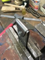
I added a top clamp to the fitting bend jig that did a great job of keeping the center fitting surface flat.

The flat, inner fitting piece were made all together in a stack. A couple TIG beads were run across an area that would eventually be trimmed. I left enough material to bore a 3/4" hole to form the inner radius than contacts the longeron. I used a scrap piece of 3/4" tubing to hold the stack while shaping it on the belt grinder. Hogged material with the 80 grit belt, and finished it off with 180. I really like the 180 grit belt for this type of work. It doesn't bite too much, and leaves a very nice edge.
 

Attachments

  • photo2489.jpg
    photo2489.jpg
    314.5 KB · Views: 0
  • photo2490.jpg
    photo2490.jpg
    307.5 KB · Views: 0
  • photo2491.jpg
    photo2491.jpg
    368.7 KB · Views: 0
  • photo2492.jpg
    photo2492.jpg
    395.7 KB · Views: 0
  • photo2493.jpg
    photo2493.jpg
    442.7 KB · Views: 0
  • photo2494.jpg
    photo2494.jpg
    427.6 KB · Views: 0
  • photo2495.jpg
    photo2495.jpg
    503.9 KB · Views: 0
  • photo2496.jpg
    photo2496.jpg
    512.8 KB · Views: 0
  • photo2497.jpg
    photo2497.jpg
    264.1 KB · Views: 0
Good show. Yes the dreaded fittings. lots of work. If you haven't already, check out rotabroaches. Amazon has 'em. The small kit goes to 3/4". They make nice round holes and stay sharp with proper use.
 
I've had a set of those in my Amazon cart for a week now... I need to go ahead and hit order.
 
Last edited:
No Title

Fabricated the brake mounts that weld on the 1-1/4" axle. Radius ground the outside, and used a 1-1/4" hole saw for the inside.

Matco apparently had more 8" wheel orders in the last couple months than they usually recieve all year. I'm guessing the introduction of the 27" Desser tundra tire is helping their 8" sales. I placed an order with them 3 weeks ago, and it sounds like my rims will be back from the anodizer/shipped end of this week.
 

Attachments

  • photo2500.jpg
    photo2500.jpg
    508.9 KB · Views: 0
  • photo2501.jpg
    photo2501.jpg
    378.4 KB · Views: 0
  • photo2502.jpg
    photo2502.jpg
    426.1 KB · Views: 0
  • photo2503.jpg
    photo2503.jpg
    592.2 KB · Views: 0
  • photo2504.jpg
    photo2504.jpg
    395.6 KB · Views: 0
No Title

Continuing to fabricate the gear/wing strut attach pieces for the fuselage.
 

Attachments

  • photo2505.jpg
    photo2505.jpg
    563.9 KB · Views: 0
  • photo2506.jpg
    photo2506.jpg
    469.5 KB · Views: 0
  • photo2507.jpg
    photo2507.jpg
    449.1 KB · Views: 0
  • photo2508.jpg
    photo2508.jpg
    643.8 KB · Views: 0
  • photo2509.jpg
    photo2509.jpg
    422.1 KB · Views: 0
  • photo2510.jpg
    photo2510.jpg
    551.7 KB · Views: 0
  • photo2511.jpg
    photo2511.jpg
    359.4 KB · Views: 0
  • photo2512.jpg
    photo2512.jpg
    549.1 KB · Views: 0
No Title

Fabricating bend fixture for forming wing strut attach points. Other than tacking the doubler plates in place, I didn't want to do any welding before forming. It will be a little tight welding the top teardrop doubler, but should be very workable with TIG. Trying to keep the heating cycles to a minimum. It would have been better to bend the fittings, and then tack the teardrops in place. The bending fixture would have been simpler.
 

Attachments

  • photo2513.jpg
    photo2513.jpg
    434.2 KB · Views: 0
  • photo2514.jpg
    photo2514.jpg
    440.6 KB · Views: 0
  • photo2515.jpg
    photo2515.jpg
    270.8 KB · Views: 0
  • photo2516.jpg
    photo2516.jpg
    255.4 KB · Views: 0
No Title

Back to welding the fuselage. It was nice break to step away from the welding for a little while, and fabricate some fittings.

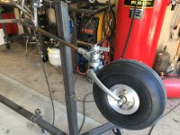
Received a wheel and brake setup from Matco today, hopefully the rest of the order will be here tomorrow. Looks great. The combination is right around 9.5lbs including the second brake caliper, I will put it on a better scale tomorrow. It is interesting to note that there are 6 through bolts around the perimiter of the wheel. I don't know if this is something that Matco is doing now on all 8" rims, or just for those intending to run tubeless. Most of the photos I have seen of the 8" rims do not have these bolts.

I was reading through the most recent Kitplanes and noticed Larry Vetterman's Cub on the cover running the double caliper 8" Matcos with 27" Dessers. Beautiful airplane, very light.
 

Attachments

  • photo2517.jpg
    photo2517.jpg
    439.8 KB · Views: 0
  • photo2518.jpg
    photo2518.jpg
    409.5 KB · Views: 0
  • photo2519.jpg
    photo2519.jpg
    354 KB · Views: 0
  • photo2520.jpg
    photo2520.jpg
    353.4 KB · Views: 0
No Title

I've been blown away with this little Makita LC1230 carbide toothed metal chop saw. It is worth every penny. The production and quality increase you get is substantial. Very smooth and square cuts. No smoke or dust. Little to no burs on cut edges. Cut pieces are not hot, and can be handled right away. You can shave a small amount off the end of a piece without the blade flexing out of track. Highly recommended.
 

Attachments

  • photo2530.jpg
    photo2530.jpg
    409.3 KB · Views: 0
  • photo2531.jpg
    photo2531.jpg
    307.7 KB · Views: 0
No Title

Now that I have the Matco wheels, I can better see why it may be advantageous for a surface to contact the bearing seal face. The bearings have a very large inside radius, and only catch the very edge of the 1.5" axle spacer over the 1.25" axle. I've decided to go ahead and fabricate a wheel spacer that slides over the axle, rests against the brake mount flange, and captures one of the brake mount bolts to keep it from rotating.

I may just fabricate an ear, with a larger hole that slides over the outside of one of the bolt heads.
 

Attachments

  • photo2532.jpg
    photo2532.jpg
    317 KB · Views: 0
No Title

Fabricated the first wheel spacer. The double caliper Matco brake mounting plate (gold) slides over the axle and bolts to the wheel side of the welded axle flange with 4 bolts (evenly spaced on a 2-1/4" diameter). The brake mounting plate has an 1-1/2 hole, leaving room for the wheel spacer to slide past it and rest against the welded axle flange. The spacer has a 2" round surface that engages the face of the bearing seal and an ear with a 1/2" hole to slide over one of the AN4 brake mounting plate bolts to prevent it from rotating on the axle. I'm using a slightly longer wheel spacer to allow the Matco brake rotor spacers. This facilitates running Bushwheels on 6" rims in the future. (Matco MH series 6" wheels require brake rotor spacers on large diameter tires to keep adequate clearance between the brake calipers and tire side wall)

I left the spacer ear slightly away from the Matco brake mounting plate, to make sure the spacer bottomed evenly against the axle flange, not the ear.

Since the bearing is now resting against the 2" surface, I didn't really need to use the thicker wall 1-1/2 spacer. It is just what I had on hand. I think 1-3/8 x 058 would work well, and be lighter.
 

Attachments

  • photo2534.jpg
    photo2534.jpg
    407.3 KB · Views: 0
  • photo2535.jpg
    photo2535.jpg
    304.2 KB · Views: 0
  • photo2536.jpg
    photo2536.jpg
    309.3 KB · Views: 0
  • photo2537.jpg
    photo2537.jpg
    418 KB · Views: 0
Last edited:
No Title

The tail spring arrived from Mark this weekend. I had to do a quick test fit, but haven't drilled any of the bolt holes.
 

Attachments

  • photo2538.jpg
    photo2538.jpg
    498.9 KB · Views: 0
Do the wheels ride entirely on the beatings? Nothing touches the axle at all other than the center of the bearing, right? Trying to paint a mental picture of the setup,
 
The bearing cone/cage/roller/seal assembly slideds over the axle. (shown in the second image) The cup portion of the bearing pressed into the hub. The seal is pressed onto the cone, and does not rotate. The seal has a flexible outer portion that lightly rides against the hub the inside of the hub. When you tighten the axle nut, it captures both bearing seals, and prevents them from rotating. The wheels ride entirely on the two bearings. I'll post a couple more photos when it is all together, it will make a little more sense.
 
No Title
 

Attachments

  • photo2541.jpg
    photo2541.jpg
    437 KB · Views: 0
  • photo2542.jpg
    photo2542.jpg
    360.2 KB · Views: 0
  • photo2543.jpg
    photo2543.jpg
    386.1 KB · Views: 0
Thanks for the video. It made everything quite clear as to the assembly of everything. That key plate is quite ingenious, I must say.
 
It is nice to take on little bite pieces of the project to break up the fusleage rotisserie welding gymnastics:) If someone felt the need, it would be pretty simple to make one that slid over an already fabricated gear leg, depending on where the holes where drilled on the axle flange. Some 1-5/8 x 058 would slip nicely over the stock 1-1/2 OD spacer. George with Matco also said they can machine some aluminum spacers that slip over the axle for around $60 each.
 
No Title

I sure enjoy this little Wezu 6" square. It get's used constantly on the airplane project. The machined, wide surfaces come in very handy. They have a 4" as well that would work well.

More welding...
 

Attachments

  • photo2553.jpg
    photo2553.jpg
    310.7 KB · Views: 0
  • photo2554.jpg
    photo2554.jpg
    483.3 KB · Views: 0
Hey LSA! It's been a couple of weeks, with no updates. I, for one, look forward to seeing your progress and innovations.
Throw me something, mister!

Bill
 
Thanks Bill, the busy summer work season has kicked off... I'll be out of town through fall. It is tough to be away from the project, but it is time to pay the bills. I'm living vicariously through all of you guys posting your progress on the forum!
 
No Title

Cut out the fuselage engine mount bushings. I left them a little long for welding, though after checking the fit, I won't leave extra length inside the fuselage for TIG welding. It is much easier to weld close to the edge of something with TIG, and it will be easier to get the torch in there without more bushing length. The bushing were chucked in a drill to debur and face. I used some emery cloth to remove the tool marks, and debur the edge. A countersink was used to debur the inside.

I am using 1/2 x 095 4130 tubing for the bushings. The factory engine mount will be used to align the bushing on the fuselage. Once they are fully welded, a 5/16 piloted chucking reamer will be used to bring the hole to the final dimensions.

I had a chance to try out one of the reamers I ordered from Pan American Tool. http://www.panamericantool.com/high-speed-steel-piloted-chucking-reamers.html I was impressed with how well it worked. I ordered the (1/4") 44-310, (5/16") 44-510, and (3/8") 33-630. Shipping was quick and cheap.
 

Attachments

  • photo2848.jpg
    photo2848.jpg
    1.2 MB · Views: 0
  • photo2849.jpg
    photo2849.jpg
    910.3 KB · Views: 0
  • photo2850.jpg
    photo2850.jpg
    1.2 MB · Views: 0
  • photo2851.jpg
    photo2851.jpg
    815.1 KB · Views: 0
One lesson from my build.

I didn't leave the bushing quite long enough on the inside and therefore didn't have enough clearance on the edge of the nut to the surrounding tubing.

Required some rework when I went to build the mount and learned this.

So make sure your bushing protrudes far enough inside and is positioned to provide enough clearance for the head of the bolt bolt/nut plus socket/wrench.
 
Thanks BTAZ, I'll bolt the bushings up to the mount for alignment, and check the nut clearance before tacking/welding. I left them 3/8" longer than plans call for.
 
No Title

Worked on fitting the factory Continental mount to the fuselage. I cut out a piece of flat melamine, cross marked center of crankshaft, and drilled the 3/8" holes for the C-85 bolt pattern. When I bolted the melamine to the engine mount I noticed the two upper bushings had the washer/flange surface welded on crooked. The lower ones looked good.

I used a cross line laser shooting directly down the fuselage C/L and a digital level to check mount alignment. Everything looked spot on until I checked the alignment when viewing the airframe vertically down. The melamine bolted in place of the engine was angle to the right around 3/4 deg. I double checked the firewall, and verified that it was 90 deg to C/L. Then I checked the mount itself and found that it was out of aligment. The melamine bolted in place of the engine was out of parallel with the where the mount bolts to the fuselage. (see photo) If I leave it as it is the back of the engine case will be on C/L and the tip of the spinner will be kicked to the right over 3/8".

Encountering this jogged my memory back to assembling the tubing kit. When I pulled the longerons together at the tail post location, one was longer than the other. Both on the top and bottom fuselage sections. Each time I checked the aligmnet of my marks and blocking, and everything was spot on. Then I put a flexible tape on the longerons themselves lengthwise and found that it wasn't aligment that was the issue, the actual longerons where different lengths. I had three choices: shift the tail post off the center line, kick the firewall alignment out of square, or trim the long longeron back. I ended up trimming the longerons equal length, and moving forward with the correct aligment. I'm wondering now if I left the longerons alone, kicked the firware over slightly if the factory engine mount would line up.

The tubing kit is cut out by hand, not CNC. There are small varitions from the plans. It was a challenge deciding whether to assemble the tubing how it fit best, or how it aligned to plan dimensions.

I plan on trimming a small amount off the two right mount bushings, and extending out the fuselage bushings on the left slightly to bring the engine mounting surface into alignment.
 

Attachments

  • photo2854.jpg
    photo2854.jpg
    2.3 MB · Views: 0
  • photo2855.jpg
    photo2855.jpg
    977.3 KB · Views: 0
  • photo2856.jpg
    photo2856.jpg
    1,016 KB · Views: 0
  • photo2857.jpg
    photo2857.jpg
    2 MB · Views: 0
  • photo2858.png
    photo2858.png
    1.3 MB · Views: 0
  • photo2859.jpg
    photo2859.jpg
    1.9 MB · Views: 0
Last edited:
No Title

After some tweaking, I'm happy with the engine mount fit and alignment. Previously I had the engine mount surface bolted tight to the melamine, and the bushings clamped tightly in the corners of the firewall tubing. It was causing several minor differences between the airframe and engine mount to stack up into a larger than acceptable misaligment. The upper mount washers that had been welded on crooked were also warping the mount as I tightened them against the melamine.

I loosened all of the mount/melamine bolts, and removed the two top bolts. Then I started slightly adjusting each bushing (that gets welded in the corners of the firewall), while keeping them within 1/16" of the corner. When everything was within satisfactory tolerances, the bushings were tacked in place.

The plans call for 1-1/2" long fuselage bushings. I cut mine 1-7/8". 3/16" of that extra length sticks out past the firewall, the other 3/16" extends a little further into the fuselage for bolt clearance. This is will make for a little easier welding, and I'll likely trim the bushing flush to the firewall after welding.

I continue to be very happy with the little Miller Diversion 165 TIG. It allows for quick, clean, easy to weld over tacks in hard to reach spaces.
 

Attachments

  • photo2860.jpg
    photo2860.jpg
    1.7 MB · Views: 0
  • photo2861.jpg
    photo2861.jpg
    1.1 MB · Views: 0
  • photo2862.jpg
    photo2862.jpg
    1.5 MB · Views: 0
  • photo2863.jpg
    photo2863.jpg
    941.9 KB · Views: 0
  • photo2864.jpg
    photo2864.jpg
    1.2 MB · Views: 0
Last edited:
Great description and nice solution to your engine mount issue. Glad to see you back at it with a vengeance, thanks again for sharing all of your experiences thus far.
 
old pictures 291.jpg Nice work. Always nice to not have to build an engine mount if you can buy one reasonable. I left my spools a little long on the bottom and I'm glad I did.
 
I welded where the bushing lays in sort of an undercut fashion so the bushing would lay in without interference. Then I welded it up the usual way. That corner is a heat eater so I switched to 3/32nd tungsten.
 
I paused for a moment and thought about doing the same. I can see that area sucking up a lot of heat and needing 3/32, though the LSA has less mass in that location than the Patrol.
 
Putting this in the comments to keep from hijacking the thread too badly. :-) What size tungsten are you using primarily? I've only had my TIG for a couple of months, and I've been practicing with 3/32". Would I be better off practicing with 1/6"? Is that the more-often used electrode?
 
I mostly use 1/16 unless I have a cluster or fitting that I know I'm going to be there a while, then I will go with 3/32nd. When I get into .065 wall and up I go with 3/32nd. Hope I'm not derailing your thread. I'm a Bhawk LSA fan. If mine wasn't so far along I would switch projects as my needs have changed. Keep up the good work.
 
Not at all Patrol28, this great information to discus, and very relevant to scratch building any of the Bearhawks. I find the 1/16th tungsten very versatile, and have been impressed with how much electrode extension you can get with the right cup. I find myself using 1/16th ER70S2 filler rod most of the time, but sometimes .045 comes in very handy for slipping into a small puddle with the electrode in close.
 
I keep .045 around too and when I want something even less for a tiny edge weld I squirt out a length of .030 out of my mig welder, snip that off and use it for filler. It's also er70s2. When I need to really stick the tungsten out I ditch the gas lens and go to a skinny cup. There is several places on the Bearhawks that needs that.
 
I didn't want to derail the flying wire for the four place thread so am posting my response here.

I built my tail feathers as close to the plans as I could and then went looking on the Univair site for wire length information.

I used Citabria streamlined upper wires for the upper set and Cub round upper wires for the bottom set, nominally $220 total and delivered from Univair stock, They worked fine for dimensions/adjustment range but, given some of the items that drive wire length are “Scaled from Plans” this isn’t a guarantee they will fit factory fuselages or others. Of course with some foreknowledge of available wire length the mounting holes/ribs could be placed exactly as needed. Note the Citabria wires are right/left hand thread while the Cub wires are right hand thread on both ends.

For the bottom at the fuselage I used regular terminals while all the others were "hot forged" per Bob's instructions.
 
No Title

*Note: Deviation from plans. Changes to the LSA shown here have not been approved by the designer.

I will be lengthening/widening the landing gear slightly, and changing the shock strut attach point/truss structure on my LSA. The result will be a wider gear stance with a little longer travel gear. It will be a bit of a hybrid between the Bearhawk/Supercub landing gear. I've done quite a bit of work on the design, and will not be going into too much detail on the forum. There is nothing wrong with the stock LSA gear, and I would advise others to follow the plans. As I continue to show progress, photos will reflect small changes to my airframe, and I wanted to address this now to avoid confusion.

I nervously picked up the TIG torch for the first time since spring, and wonder "do my hands remember how to do this?" It is a totally different experience for me welding on an airframe, as opposed to something like a trailer, or truck rack. I can't help but keep in my awareness that this structure will be carrying me thousands of feet above the ground. It is good to be back welding again.
 

Attachments

  • photo2886.jpg
    photo2886.jpg
    1.2 MB · Views: 0
  • photo2885.jpg
    photo2885.jpg
    1 MB · Views: 0
Last edited:
No Title

Continued cutting and tacking additional fuselage tubing to accomodate the gear modifications. I finally gave in and ordered the Sharpie DX tungsten grinder from Arc-Zone.com https://www.arc-zone.com/sharpie-grinder-a-ptgk-dx I wish I had done it much sooner, it works very well.
 

Attachments

  • photo2930.jpg
    photo2930.jpg
    1,010.9 KB · Views: 0
  • photo2931.jpg
    photo2931.jpg
    1.8 MB · Views: 0
  • photo2932.jpg
    photo2932.jpg
    1.2 MB · Views: 0
  • photo2933.jpg
    photo2933.jpg
    1.3 MB · Views: 0
That tool's been on my mind! I also need to find a set of optics that will allow me to see well. I haven't quite found the right combination yet. If I could do that, I probably wouldn't have to regrind contaminated tungstens quite as often :-)
 
I have a belt grinding attachment on the right side of the bench grinder, and a wheel on the left. It is the perfect combination for notching tubing, but doesn't leave a wheel that can be dedicated to sharpening tungsten. I use a short back cap/tungsten on the torch, and do not like how close my finger have to be to the wheel on the bench grinder to get a good point. I've been meaning to try a magnifying insert for my helmet, some of those custers make it hard to get close enough for a good view. Half the battle of getting a good weld on an airframe is having a good view of what you are doing.
 
"Meaning to try a magnifying insert". Ha! Now we know you're a youngster. :).
To sharpen tungsten, I chuck it in my cordless drill and spin it slowly, while holding the tip on the belt sander (parallel to the sanding belt). Works pretty good. But I like your sharpener!

Bill
 
As a software nerd, I spend an enormous amount of time in front of the computer screen. My eyesight has degraded over the past few years, and I'm trying to find the right combination of cheaters. Like U2, I still haven't found what I'm looking for.
 
Regarding welding cheater lenses; A number of years back, I noticed that my welding skills were degrading. Strangely enough, I decided to replace the clear cover lenses and voila! I could see the weld process better and my welds improved. Imagine that. The cover plates were so messed up, I could barely see through them. Who'd have thought that would be a problem... At that point, I figured I'd try my reading glasses, under the helmet. The welds improved further! Now, don't get me wrong; I'm not a great welder, but I can hold my own, when I can see the puddle. No matter how great your equipment is, if you're not in a comfortable position and you can't see the weld, your welds aren't going to be optimal. My helmet doesn't use standard size lenses, so I can't put a cheater in it. But reading glasses, a notch or two above what I read with, work just great.
Moral of the story; Don't sweat getting the perfect cheater lenses. Reading glasses work fine.

Bill
 
Great info Bill. I wear glasses for a slight astigmatism. This spring I ordered a pair of glasses from Zenni Optical for under $40 shipped. I use these for work and in the shop. I have been meaning to order another pair with some magnification. Some of those clusters keep your helmet a little far away to really see what is going on with the weld. I'd highly recommend getting set up right with your helmet/vision before welding an airframe. It is well worth the time and effort.
 
That is how I learned to sharpen tungsten as well, though I don't really like using a drill for 1/16". I prefer to keep tungsten dust completely away from my regular grinding. This little tool tucks nicely under my welding stool. It has a slot for trimming the contaminated tip, and it puts a perfect point on the 1/16" tungsten very quickly.
 
No Title

*Note: Deviation from plans. Changes to the LSA shown here have not been approved by the designer.

Should be finished with the additional fuselage tubing to accommodate the gear modifications tomorrow. I'm welding some of the joints as I go for ease of access.
 

Attachments

  • photo2936.png
    photo2936.png
    619.9 KB · Views: 0
  • photo2937.jpg
    photo2937.jpg
    1 MB · Views: 0
  • photo2938.jpg
    photo2938.jpg
    1.2 MB · Views: 0
  • photo2939.jpg
    photo2939.jpg
    1.8 MB · Views: 0
Don't sweat getting the perfect cheater lenses. Reading glasses work fine.

Bill

Yep; I think this is a good idea, what I do as well... inside the helmet I use the full-sized reading glasses in the correct diopter, I've tried the smaller "look-over" glasses that are popular, but seemed like they were always in the wrong spot, so I use cheap, full-sized... although once the helmet is off, I'm immediately "blind" until I take the glasses off...
 
x2. When I am having a "welding day" I am going back and forth between my regular bi-focals and welding goggles with my strong reading "Welding" glasses. Its common to light the torch, put the goggles on, and get ready to resume welding only to think "Why can't I now see?"...shut everything down, take off the goggles to clean the lenses only to find that they are not the reading "welding" glasses rather my bifocals...another frustrating Alzheimer's moment.
 
I recently bought a pair of miller auto darkening glasses that work well in tight places where regular helmet would be clumsy.if I recall they were a little over $200
When you tig weld on your airframe do you do any post weld heat treating?
 
Bdflies Your Patrol is looking great! Thanks for checking in. I chose to hit pause on the LSA build around a year ago after encountering a couple concerns with the project. I'm just now revisiting the build and deciding how to proceed. A big thank you to bway for the excellent flight testing reports on the LSA. It's been good to get caught back up on the forum and see everyone's progress.
 
Last edited:
Thanks about the Patrol! I enjoyed every minute spent building and now enjoying flying it!
Very cool skis. I can see many possibilities with that router...
"couple concerns"?

Bill
 
I was disappointed to discover quite a few of the small parts I had fabricated developed surface rust over the last year despite being inside and dry. After some research I went by O'Reillys and found a can of Rust-Block from the same company that makes Evapo-Rust (great stuff). It is a non toxic indoor rust inhibitor that dries to a clear mat finish. The product can be rinsed off with warm water when you are ready to continue fabrication or paint. I tested it on one of my axles and expedited the dry time with a heat gun. It sprays out clear and dries to a non tacky surface.
 

Attachments

  • photo4262.jpg
    photo4262.jpg
    261.5 KB · Views: 0
  • photo4263.jpg
    photo4263.jpg
    317.9 KB · Views: 0
Last edited:
LOL....If any one wants to participate in a Bearhawk build with bit coins, here is an address for my project :)

18mVfR9hR6rnw2XutCZR8FgqHKXBuyk94M
 
*Note: Deviation from plans. Changes to the LSA shown here have not been approved by the designer.

Working to wrap up a couple projects to make room for the fuselage coming down off the shop ceiling this week. I've taken some time in the evenings to dial in the extended gear design. It was interesting to run tubing load calculations on the stock LSA landing gear and cub gear. The rear tube on the Bearhawk gear carries a tremendous amount of compression when the gear is loaded. The shallow angle between the gear strut/landing gear leg on the Bearhawk loads the strut quite heavily when compared to cub type gear. This is evident when looking at the cub's small single tube external landing gear cabane vs the Bearhawk's much more heavily constructed internal truss that carries the gear strut loads.

I've opted to move the gear strut loads to an internal inverted pyramid truss centered on the axles. This drops the strut attach point down, increases the angle between the gear leg/strut, and allows a wider gear stance/additional gear travel. This also splits the compression loads evenly between the two gear leg tubes when loaded. The belly will be slightly deeper to accommodate the truss. It has taken a significant design effort to be comfortable with making these changes and I do not advocate or suggest doing so. In short, follow the plans! I have some specific and unique needs that warrant the time/effort.
 

Attachments

  • photo4300.jpg
    photo4300.jpg
    429 KB · Views: 0
Last edited:
I like your modification. It reduces the gear leg and strut loads, simplifies maintenance and opens up a congested area where the struts attach per plans. Are you going to go with a softer spring and increase the strut travel?
 
Yes, to get comparable travel/rate to the stock gear I would need a slightly longer/softer spring because of the geometry change. Dayton and Danly both have a very extensive catalogs with detailed specs. I'd like to gain a little travel and have a larger margin before the travel bottoms out in an extreme drop. The big tires help as well.
 
*Note: Deviation from plans. Changes to the LSA shown here have not been approved by the designer.

Spent some time this evening really digging into the spring specifications, gear geometry, and load calculations. I found this video of a Cessna 180 clearing some pylons and coming down hard on the gear! It looks like he tried to come in with power to slow his descent and the engine was loaded up from the slow approach. It's impressive the Cessna gear can handle a hit like that... I wonder what the gearboxes looked like afterwards.

<iframe width="560" height="315" src="https://www.youtube.com/embed/0QzikkPruMQ?start=365" frameborder="0" allow="autoplay; encrypted-media" allowfullscreen></iframe>
 

Attachments

  • photo4310.jpg
    photo4310.jpg
    92.7 KB · Views: 0
The fuselage descended from on high and landed in the rotisserie this afternoon. Unfortunately I found the tube in front of the spar had been damaged and needed to be replaced. I had one side of it fully welded so it took some creative slicing with the 2" cutoff wheel to extract the it. After some grinding and fitting the new piece is in place and it felt great to have the TIG torch in hand again.
 

Attachments

  • photo4323.jpg
    photo4323.jpg
    448.3 KB · Views: 0
  • photo4324.jpg
    photo4324.jpg
    498.7 KB · Views: 0
  • photo4325.jpg
    photo4325.jpg
    322.9 KB · Views: 0
  • photo4326.jpg
    photo4326.jpg
    747.4 KB · Views: 0
  • photo4327.jpg
    photo4327.jpg
    326.6 KB · Views: 0
  • photo4328.jpg
    photo4328.jpg
    291.5 KB · Views: 0
  • photo4329.jpg
    photo4329.jpg
    534.7 KB · Views: 0
Last edited:
Torch, tungsten, and filler size, if you don’t mind?

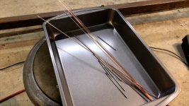
The torch is a CK FL1325SF FlexLoc 130A 25' Superflex lead and I couldn't be happier with it. If your going to weld an airplane fuselage get rid of the big torch/fat lead that comes with most TIG machines. The superflex lead makes a world of difference. The 25' lead allows work up and down the fuselage without dragging your machine around. I make a wrap around my arm with the lead and leave a small loop of slack to allow torch movement. I initially used 1/16 and 3/32 tungsten but now use 3/32 exclusively. 028 and 035 are thin but when you get a cluster with a bunch of tubes it often requires a little more heat than I like to run with 1/16. I keep a tray of .045 and 1/16 ER70S-2 filler rod on hand with several sharpened tungsten. It's easy to keep the tungsten clean while bench welding but I occasionally get some filler metal on the tip while doing gymnastics inside the fuselage. I change between .045 and 1/16 filler rod depending on where I'm welding in the cluster. Sometimes it's difficult to get 1/16 into a small puddle deep inside a complex cluster without disturbing the arc. Other times the 1/16 helps keep the puddle cooler and requires less hand movement to feed the weld. I use a large diameter #10 cup/gas lens. You can dial up the gas a little and get quite a bit of electrode extension when needed. The large cup stays cool, shields to arc nicely, and the back of it makes a great handle.

I've been looking around for where I purchased the gas lens kit. I think it was around $30 for a kit containing 1/16 - 1/8 lenses and #8-12 cups. Some of the large gas lens setups are very overpriced.
 

Attachments

  • photo4341.jpg
    photo4341.jpg
    385.9 KB · Views: 0
  • photo4342.jpg
    photo4342.jpg
    371.4 KB · Views: 0
Last edited:
Thanks for the info. I have the stock #17 flex torch still, but did get a stubby gas lens kit from Jody at Weldmonger. Haven't yet had a chance to do anything with it yet, though.
 
Do you weld with that much tungsten extension? I consider myself pretty gang-ho with stick out, but you've got me there!

Bill
 
Back
Top