North Carolina LSA Kit Build Underway

slscott715

LSA Quick Build
Hey guys,

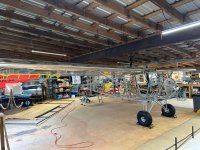
My name is Sam Scott and I'm a full-time A&P mechanic with a serious case of the flying/building bug. I've been lurking here for the better part of a decade and planning an LSA build since I saw Bob's prototype at a local fly-in back in 2015. My daily flier is a 1946 J3 Cub and I absolutely love most things about it. The majority of my flying is very local, in and out of short grass strips and solo. The J3 is the perfect for this but I do occasionally take a cross-country (+-200NM) and would like to carry a passenger from time to time. This is where the LSA appeals to me.

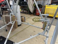
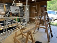
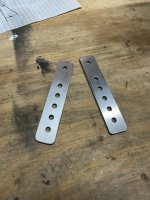
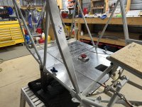
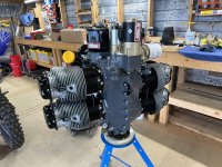
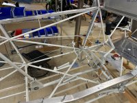
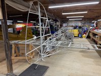
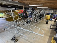
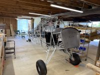
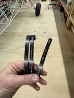
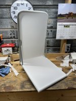
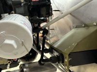
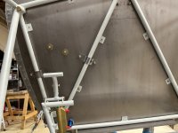
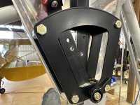
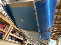
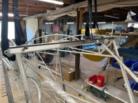
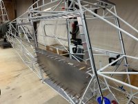
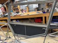
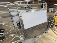
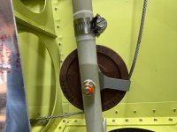
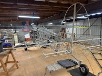
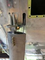
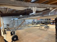
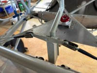
I'll be using a C-85-12F and Sensenich ground adjustable prop. I will be using a battery-only electrical system to power a starter and GTR200B comm radio. I'm doing this to save the weight and expense of an engine-driven electrical system & ADS-B/transponder. My kit arrived on Easter weekend 2025 and building was underway within 12 hours of the kit being unloaded. I've had the kit for about 2 weeks at the time of this writing and so far, I've installed the stringers, window frames, fit and drilled the floorboards, installed the rudder pedals and brakes, fabricated rudder cables, installed the fuel selector/gascolator and plumbed the fuel system. I've been extremely happy with the quality of the kit and the support I've received from Virgil and Mackenzie Irwin at Bearhawk Aircraft. I'm having a blast building so far and I hope to post updates periodically throughout the process.
 

Attachments

  • IMG_1414.jpg
    IMG_1414.jpg
    2.9 MB · Views: 7
  • IMG_1443.jpg
    IMG_1443.jpg
    1.3 MB · Views: 6
  • IMG_1463.jpg
    IMG_1463.jpg
    2 MB · Views: 4
  • IMG_1494.jpg
    IMG_1494.jpg
    1.9 MB · Views: 6
  • IMG_1535.jpg
    IMG_1535.jpg
    1.9 MB · Views: 6
  • IMG_1537.jpg
    IMG_1537.jpg
    2 MB · Views: 6
  • IMG_1539.jpg
    IMG_1539.jpg
    2.9 MB · Views: 5
  • IMG_1543.jpg
    IMG_1543.jpg
    1.6 MB · Views: 4
  • IMG_1541.jpg
    IMG_1541.jpg
    1.8 MB · Views: 5
  • IMG_1546.jpg
    IMG_1546.jpg
    1.4 MB · Views: 5
  • IMG_1560.jpg
    IMG_1560.jpg
    2.7 MB · Views: 6
  • IMG_1561.jpg
    IMG_1561.jpg
    2.7 MB · Views: 5
  • IMG_0774.jpg
    IMG_0774.jpg
    1.8 MB · Views: 6
  • IMG_0773.jpg
    IMG_0773.jpg
    2.6 MB · Views: 6
  • IMG_1555.jpg
    IMG_1555.jpg
    1.7 MB · Views: 5
  • IMG_1556.jpg
    IMG_1556.jpg
    2.2 MB · Views: 6
Brilliant project. One consideration... the transponder rule exempts aircraft without engine-driven electrical systems from equipage; the ADS-B rule differs a bit in that it exempts aircraft without an installed electrical system from equipage. I don't believe the FAA has a problem with self-contained battery-powered starting systems on powered gliders, etc., but having a panel-mount comm radio might be pushing that interpretation of 91.225e.

I would suggest two things: a) ensure you are on solid regulatory ground with the FAA (FSDO avionics inspector and the ACO) re: what constitutes an installed electrical system, and b) provision for a belly-mount antenna (ground plane; cable access) for operation at 5W or less at 978MHz or 1090MHz to accommodate both future changes to 91.225e interpretation (this stuff happens, and seeing government agencies tends to get expensive quickly) and the pressures that new entrants such as AAM and UAS are placing on the current 'see and avoid' visual separation system.
 
Thanks SpruceForest for the heads up. FAR 91.225(e) states “the requirement of paragraph (b) of this section do not apply to any aircraft that was not originally certificated with an engine-driven electrical system, or that has not been subsequently certified with such a system installed, including balloons and gliders. These aircraft may conduct operations without ADS-B Out in the airspace specified in paragraph (d)(4) of this section. These aircraft may also conduct operations in the airspace specified in paragraph (d)(2) of this section if those operations are conducted-
(1) Outside of any Class B or Class C airspace area; and
(2) Below the altitude of the ceiling of a Class B or Class C airspace area designated for an airport, or 10,000 feet MSL, whichever is lower.”

The airspace specified in 91.225(d)(2) is where I hope to be able to operate due to my proximity to CLT. It seems to me that the engine-driven electrical system exemption applies to ADS-B Out as well, but maybe I’m missing something. I’ll check with the guys at my FSDO.
 
Changed 4/2/25... finally. We've been waiting for that change to post...should be good. Still recommend provisioning for ADS-B out antenna. PM if you want to know why.
 
Thanks Jared!
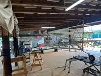
I’m glad to finally be here with something to contribute. Visitors are welcome any time. I’m working in my hangar at a grass strip near Boonville, NC. I’d especially love to have some fly-in visitors. Anybody interested in coming by can send me a message and I’ll tell them how to find me. I’ll be there pretty much all weekends unless I’m out flying.
 
My goal this week was to get the tail surfaces mocked up and the elevator and trim control systems put together. This proved to be an overly-ambitious goal.

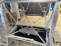
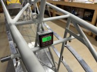
I leveled the fuselage and got the -2 degree incidence set on the stab tube. I had to remove approximately .150” from each spacer to obtain this, adjusting each spacer individually to maintain level left to right. I did this with a little known tool called a reverse spotface cutter. This made removing material from the spacers with precision a breeze. After installing the stabilizers, I found the stab struts too short and the upper flying wires too long. Also, the elevator hinge bearings that came with my kit were too large, as others have experienced, so I was unable to install the elevators. These problems made me suspicious that something may be dimensionally off with my fuselage/tail parts. After two days of checking all the dimensions against the plans, I’ve not been able to find any discrepancy. I squared the tail using straps to get the required dimensions for struts and flying wires.

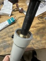
I did manage to assemble my shock struts this week after gettin g the springs in from backorder. I started by thoroughly cleaning all parts of the shock assembly. The IDs of the piston tubes were packed with a combination of grease and chips and required extra attention. I urge anyone assembling their shocks to inspect and clean their piston tubes before assembly as fluid does need to pass freely through the ID and at least one of mine was completely blocked. After cleaning, assembly went smoothly with the use of a piece of tubing and a bolt to compress the spring, allowing the snap-rings to be installed. I installed the rod-ends with a bit of EZ-Turn lubricant (previously now as Fuel Lube) on the threads. This acts as a thread lubricant and also seals the thread as hydraulic fluid will be present on the back side of these threads.

As always, Virgil and the folks at Bearhawk have been extremely reliable and swift to help with these issues and it is much appreciated. Hopefully, I’ll have more progress to report next week.
 

Attachments

  • IMG_1615.jpg
    IMG_1615.jpg
    1.2 MB · Views: 2
  • IMG_1609.jpg
    IMG_1609.jpg
    1.2 MB · Views: 1
  • IMG_1614.jpg
    IMG_1614.jpg
    1.2 MB · Views: 1
  • IMG_1611.jpg
    IMG_1611.jpg
    1.4 MB · Views: 1
  • IMG_1612.jpg
    IMG_1612.jpg
    1.5 MB · Views: 1
  • IMG_1612.jpg
    IMG_1612.jpg
    1.5 MB · Views: 2
  • IMG_1595.jpg
    IMG_1595.jpg
    1 MB · Views: 2
  • IMG_1610.jpg
    IMG_1610.jpg
    1.7 MB · Views: 2
  • IMG_1602.jpg
    IMG_1602.jpg
    1.8 MB · Views: 1
  • IMG_1600.jpg
    IMG_1600.jpg
    2 MB · Views: 1
  • IMG_1601.jpg
    IMG_1601.jpg
    1.8 MB · Views: 1
  • IMG_1603.jpg
    IMG_1603.jpg
    1.9 MB · Views: 1
  • IMG_1605.jpg
    IMG_1605.jpg
    2.8 MB · Views: 1
  • IMG_1599.jpg
    IMG_1599.jpg
    2.8 MB · Views: 1
Have you fit your struts to your gear legs yet? It seems most of this design require some work to get alignment without binding. The newer Patrol and maybe others have heim joints on both ends. The LSA still has the bushing on the lower attach point which makes alignment at the top a big challenge. If I had to do it again, I would have assembled the shock tubes without the springs to allow full range of motion on the gear to check alignment in all positions. one of mine required a hefty bend in the strut to get it to work. There is still a rocking couple in the lower attach point which is not ideal, but I bent the strut enough so it allowed full motion without undue stress on the lower bolt. Time will tell if this is ok. The alternative is to modify the strut and lower attach point to accept the heim joint.
 
I haven’t fit the gear legs and struts yet. I did not realize this was an issue. I’ll remove the springs and check alignment as you’ve described. I appreciate the heads-up.
 
A decent amount of progress was made on the LSA this week despite some setbacks.

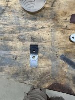
Continuing on with the tail, I found that my tail brace wires were quite a bit too long on top and just slightly long on the bottom. After speaking with Virgil, I found out that my tail brace wires came from a new supplier and may have been improperly sized. With the help of my flying/build buddy, Randy, we measured everything against the plans to verify there were no issues with the fuselage or tail. All checked out ok so we started looking at ways to make the flying wires work if possible. We determined that I could make new upper flying wire tabs that were shorter than the ones supplied in the kit as well as shortening the kit supplied tabs on the stabilizer upper surface. This allowed me to use the upper flying wires by cutting off the excess threads protruding through the clevis. The lower flying wires were usable after shortening the threads by about 1/4". All the flying wire tabs supplied with the kit had 1/4" holes drilled in them and the flying wire fork ends had 3/16" holes so I made a couple bushings to use in the lower flying wire tabs. This problem was taken care of on the upper tabs when I shortened them and re-drilled the holes. Finally, all the tail brace wires were installed and the tail squared to the fuselage. The bearings for the elevator center hinge were not in my kit, so I used some bearings from a local supplier for mock-up while waiting on the proper bearings to come from Bearhawk.

With the tail all installed and rigged, I next began working on the elevator & trim control systems. I installed the torque tube, control sticks, elevator pivot, and the fwd and center elevator pushrods. When I got to the aft elevator pushrod, I discovered that the threads in the pushrod were 5/16"-24 and my rod-ends were 3/8"-24. I referenced the plans to see how it should be configured and was not able to find a specific callout on the aft elevator pushrod for thread sizes or rod ends used. Assuming the rod ends are the same as the center pushrod, it should be 3/8" and being that those were supplied in the kit, I concluded that the pushrod must have the wrong threads. I ground away the nuts welded on the ends of the pushrod, opened up the holes to 3/8 and welded AN315-6R nuts to each end. The rod-ends did not have bushings so I turned a couple out of brass that I had on hand. I was then able to hook up the elevator pushrod and make adjustments to get proper travel.

With the elevator controls in, the trim controls were next on deck. I mounted the trim lever, shortened the trim torque tubes as required for proper placement of the control horns, installed the trim tab push/pull rods and set everything at mid-travel. With the system mocked-up, I drilled the horns to the torque tubes and installed bolts. I made bushings to go on the threaded studs of the trim lever and made links out of .090 4130 to attach turnbuckles to. Fairleads were installed and the cables fabricated in place. With the trim system all mocked up, I cut the trim tabs loose from the elevators and tried it out. Some adjustments to the turnbuckles to obtain proper cable tension and placement of the lever finished off the trim system.

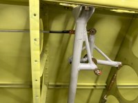
With the tail and fuselage controls all completed, I turned my attention to the landing gear. Per Arborite's suggestion, I removed the springs from the shock struts, installed the gear legs and and checked for issues with alignment and binding throughout the range of motion. After the issues I had with the tail, I was happy to find that everything moved freely without modification. I reinstalled the springs in the shock struts and attempted to fit the wheels to the gear legs. The bearings would not go on the axles beyond the threads so I mic'd the ID of the bearings and the OD of the axles and found that there was only about .0007" clearance between the two. A little work on the axles with emery cloth did the trick so I installed the brake torque plates, spacers and wheels/tires on the gear legs for the first time. There have been others that had issues with the Matco nuts being too tight on the threads but mine went on ok, luckily.

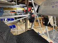
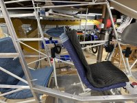
At this point, the airplane is entirely too close to being ready for "hangar flying" status so I turned my attention to the tailwheel. The tailwheel spring would not insert fully into the socket on the fuselage because of some weld penetration into the ID of the socket. A 3/4" flap disc in a die grinder made quick work of that and the tailwheel spring was installed. The tailwheel slid onto the tailwheel spring and with a little reaming to remove paint from the holes, it was bolted on. I was then able to set the airplane down on its own wheels, install the seat with a bottom cut out of some scrap OSB and cushions made from shipping blankets and try the airplane on. Stick and rudder pedal geometry felt great and notes were taken for positioning of the throttle controls.

This weeks progress was very rewarding and felt like a big step forward. It was neat to be able to sit in the cockpit and make airplane noises for the first time. I will upload pictures associated with this post in the next day or two.
 
Here are the pictures from last night’s post. I guess I was more focused on building than pictures this week. If there’s any details that someone would like to see, let me know and I’ll try to take some more photos.
 

Attachments

  • IMG_1628.jpg
    IMG_1628.jpg
    1.9 MB · Views: 1
  • IMG_1639.jpg
    IMG_1639.jpg
    2.4 MB · Views: 1
  • IMG_1645.jpg
    IMG_1645.jpg
    2.6 MB · Views: 1
  • IMG_1627.jpg
    IMG_1627.jpg
    2.6 MB · Views: 1
  • IMG_1640.jpg
    IMG_1640.jpg
    2.9 MB · Views: 1
  • IMG_1658.jpg
    IMG_1658.jpg
    1.4 MB · Views: 2
  • IMG_1663.jpg
    IMG_1663.jpg
    1.3 MB · Views: 1
  • IMG_1660.jpg
    IMG_1660.jpg
    1.5 MB · Views: 1
  • IMG_1659.jpg
    IMG_1659.jpg
    1.5 MB · Views: 1
  • IMG_1653.jpg
    IMG_1653.jpg
    1.7 MB · Views: 1
  • IMG_1657.jpg
    IMG_1657.jpg
    1.6 MB · Views: 1
  • IMG_1655.jpg
    IMG_1655.jpg
    2.3 MB · Views: 2
  • IMG_1654.jpg
    IMG_1654.jpg
    2.4 MB · Views: 1
  • IMG_1626.jpg
    IMG_1626.jpg
    3.3 MB · Views: 1
  • IMG_1649.jpg
    IMG_1649.jpg
    2.4 MB · Views: 1
  • IMG_1648.jpg
    IMG_1648.jpg
    2.6 MB · Views: 2
Between working and a couple flying adventures this week, I was able to make some progress on the LSA.

Having the tail feathers, trim and elevator control systems all rigged, I marked the hinge locations, noted the exit points of the rudder cables and trim horns through the fabric and removed the tail feathers. This helped a lot with getting around my cramped workspace.

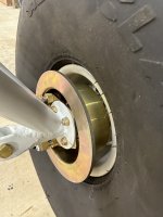
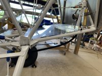
I set my sights on the landing gear next. I clamped the brake caliper torque plates to the mounting plates and, once satisfied with the placement of them, I put an index mark across the two. The gear legs were then removed from the airplane for jigging and drilling. I used the spacer supplied with the kit to center the torque plate around the axle. The torque plate ID is 1.5” and the spacer OD is quite a bit smaller so I wrapped masking tape around the spacer until the OD would fit snugly inside the ID of the torque plate. This held the torque plates centered while I lined up the index marks and clamped them tightly to the mounting plates. I used a 12” drill bit to drill the holes, installing temporary bolts in each hole as they were drilled to maintain alignment. Once all the holes were drilled, I had to use a pencil grinder to remove weld near the backside of the bolt holes to allow the nuts to sit flat against the mounting plate. I seem to recall an engineering change from a while back that recommended stitch welding the mounting plate to the axle to alleviate this issue but the gear legs supplied with my kit were welded all the way around. If anyone is familiar with this, let me know. After a little de-burring and touch up paint, the brakes were mounted.

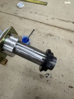
I noticed when I installed the wheels, I couldn’t quite get the bearings fully seated before the nuts got tight. With the wheels removed and the nuts threaded onto the axles, I found that they got tight about 1/4” from the end of the threads. I used a 1-1/4“x16 split die to cut the threads a little deeper until the nut would run all the way down to the end of the threads. Reinstalling the wheels proved this to be successful so I torqued the axle nuts according to Matco’s instructions and marked the hole locations for the axle nut cotter pins. The wheels were once again removed and the holes drilled. I reinstalled the gear legs, shock struts, wheels and brakes.

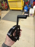
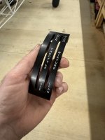
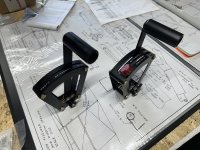
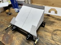
I focused on mounting throttle quadrants next. This led me into a neat little side project. The throttle quadrants I got with the kit are beautiful, anodized aluminum, two-lever units popular with the RV crowd. The only issue is I don’t really want a mixture control in the back seat. I couldn’t find a single-lever quadrant to match the ones I have so I decided I could make one. I disassembled the extra two-lever quadrant and rough-cut the mixture side off the machined top cover with a bandsaw. My friend Randy has access to a milling machine at his work, so we used it to remove the remaining material from the top cover, allowing the side cover to sit flush against its side. The bushings at the bottom bolts were shortened to match the width of the top cover and the bolts were all exchanged for shorter ones. The mixture lever and additional spacers were removed from the buildup. To retain the functionality of the friction lock, I had to cut additional threads on the shank of the replacement AN3 bolt before installation. With all the parts modified as needed and painting the exposed aluminum to match the black anodizing, I reassembled the throttle quadrant. It worked out perfectly and looks exactly like I wanted it to.

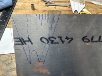
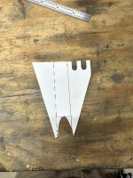
There are no provisions for mounting the throttle quadrants so I had to figure out where and how to mount them. I mocked-up the front and rear seats, floorboards and rudder pedals. I stacked shipping blankets in the seats to simulate my future cushions and sat in each seat, trying different throttle positions until I settled on my preferred locations. Now that I established the “where”, it was time to figure out the “how”. I used poster board to make templates for mounting brackets for each throttle and translated that onto some .040” 2024 aluminum sheet. After cutting and bending the aluminum brackets, they were test fit and drilled to their final locations. Once satisfied with the fitment, I drilled the mounting holes and installed the throttle controls to the brackets. These assemblies were clecoed back into their respective positions. With all of the primary flight/engine controls mounted, hangar flying commenced. Man, does this thing sit good!
 

Attachments

  • IMG_1696.jpg
    IMG_1696.jpg
    1.1 MB · Views: 2
  • IMG_1681.jpg
    IMG_1681.jpg
    1.4 MB · Views: 2
  • IMG_1682.jpg
    IMG_1682.jpg
    1.6 MB · Views: 2
  • IMG_1680.jpg
    IMG_1680.jpg
    1.3 MB · Views: 2
  • IMG_1695.jpg
    IMG_1695.jpg
    2.3 MB · Views: 2
  • IMG_1693.jpg
    IMG_1693.jpg
    1.6 MB · Views: 3
  • IMG_1697.jpg
    IMG_1697.jpg
    1.7 MB · Views: 2
  • IMG_1689.jpg
    IMG_1689.jpg
    1.4 MB · Views: 2
  • IMG_1687.jpg
    IMG_1687.jpg
    1.8 MB · Views: 3
  • IMG_1692.jpg
    IMG_1692.jpg
    2.9 MB · Views: 3
  • IMG_1690.jpg
    IMG_1690.jpg
    1.7 MB · Views: 3
  • IMG_1688.jpg
    IMG_1688.jpg
    2.1 MB · Views: 2
  • IMG_1686.jpg
    IMG_1686.jpg
    2.1 MB · Views: 2
  • IMG_1691.jpg
    IMG_1691.jpg
    2.2 MB · Views: 3
  • IMG_1683.jpg
    IMG_1683.jpg
    2.6 MB · Views: 4
Additional pictures from this weeks progress…
 

Attachments

  • IMG_1707.jpg
    IMG_1707.jpg
    2.1 MB · Views: 1
  • IMG_1719.jpg
    IMG_1719.jpg
    1.7 MB · Views: 2
  • IMG_1703.jpg
    IMG_1703.jpg
    2 MB · Views: 1
  • IMG_1718.jpg
    IMG_1718.jpg
    1.8 MB · Views: 2
  • IMG_1710.jpg
    IMG_1710.jpg
    2.1 MB · Views: 1
  • IMG_1708.jpg
    IMG_1708.jpg
    2.5 MB · Views: 1
  • IMG_1713.jpg
    IMG_1713.jpg
    2.2 MB · Views: 2
  • IMG_1711.jpg
    IMG_1711.jpg
    2.6 MB · Views: 1
  • IMG_1716.jpg
    IMG_1716.jpg
    2.7 MB · Views: 2
  • IMG_1717.jpg
    IMG_1717.jpg
    2.7 MB · Views: 2
  • IMG_1712.jpg
    IMG_1712.jpg
    2.6 MB · Views: 2
  • IMG_1715.jpg
    IMG_1715.jpg
    2.9 MB · Views: 1
  • IMG_1709.jpg
    IMG_1709.jpg
    1.9 MB · Views: 1
  • IMG_1706.jpg
    IMG_1706.jpg
    2.6 MB · Views: 1
  • IMG_1704.jpg
    IMG_1704.jpg
    2 MB · Views: 1
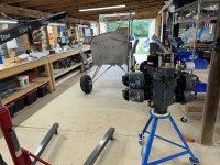
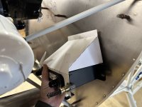
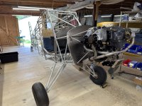
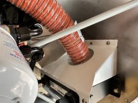
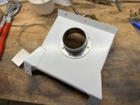
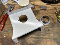
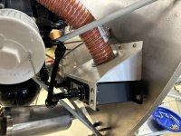
A little more progress to report this week. I covered the seat frames with heavy duty fabric in preparation to drop them off for upholstery. I bolted the engine mount on and installed the engine so I could begin mounting components on the firewall. I started with the brake reservoir, then started mocking up the cabin heat box. I ultimately decided to order a different cabin heat box because I couldn’t get “push-off/pull-on” controls with the inlet/exit holes oriented like I needed. From there, I moved on to the oil cooler mounting. I found a location that would place the mounting holes adjacent to the fuselage tubing behind the firewall. I fabricated clamps that would transmit the load of the oil cooler directly to the tubing rather than relying on the thin firewall to support it. I mocked up an oil cooler shroud/brace out of poster board and after a few iterations, I transferred the layout to .040” aluminum and cut/bent up the final part. I will be riveting on an 3” duct flange to the brace once it arrives from ACS. All of the associated mounting holes were drilled through the firewall and all parts installed with temporary hardware to check fitment. While everything was in place, I made up the oil cooler hoses. The oil cooler mounting parts were then removed to be prepped and primed with EP-420 epoxy primer.
 

Attachments

  • IMG_1756.jpg
    IMG_1756.jpg
    1.6 MB · Views: 1
  • IMG_1742.jpg
    IMG_1742.jpg
    2.1 MB · Views: 1
  • IMG_1731.jpg
    IMG_1731.jpg
    2.2 MB · Views: 1
  • IMG_1754.jpg
    IMG_1754.jpg
    2.2 MB · Views: 0
  • IMG_1736.jpg
    IMG_1736.jpg
    2.4 MB · Views: 0
  • IMG_1723.jpg
    IMG_1723.jpg
    2.1 MB · Views: 1
  • IMG_1758.jpg
    IMG_1758.jpg
    1.7 MB · Views: 1
  • IMG_1767.jpg
    IMG_1767.jpg
    1.5 MB · Views: 2
  • IMG_1764.jpg
    IMG_1764.jpg
    2.1 MB · Views: 2
  • IMG_1763.jpg
    IMG_1763.jpg
    2.3 MB · Views: 2
  • IMG_1759.jpg
    IMG_1759.jpg
    3 MB · Views: 0
  • IMG_1757.jpg
    IMG_1757.jpg
    2 MB · Views: 1
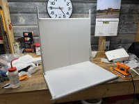
I started this week with priming a batch of parts with EP-420 epoxy primer. After the primer cured, I installed nutplates on all parts that required them. I decided on a location and mounted the cabin heat box. The eyeball pass-throughs for the throttle, carb heat and cabin heat controls were then located, drilled and mounted. I would suggest to anybody installing the eyeball pass-throughs to buy the drill jig P/N AS-231. This makes locating and drilling the holes much easier and more accurate. I punched out the large holes in the center with a Hougen Rotacut hole cutter. If you don't have this set, do yourself a favor and pick one up. It's one of those rare tools that does its job so well, I'm amazed every time I use it.

The tubing arrived for the throttle slave rod to connect front and rear throttle controls so I turned my attention to that. I started by removing the throttle levers from the quadrants and drilling new holes for the slave rod to attach. These holes were drilled the same distance from the pivot on each lever so the throw of the levers would be the same front and rear. The quadrants were reassembled and measurements taken to determine slave rod length. I initially thought about welding nuts on the ends of the tube and using clevises for adjustability but I found it just as easy, cheaper and lighter-weight to form each end of the tube into a clevis. After installing it and verifying throttle operation, I removed the slave rod, throttle quadrants and throttle mounts for priming/painting.

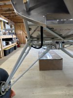
Planning for removal of the gear legs, I went ahead with plumbing the brake system. A few of my fittings are on backorder but I had enough on hand to do one side up to the master cylinder. I installed all the fittings in the right-side caliper and master cylinder, located and drilled a hole in the top of the gear leg for a 90 degree bulkhead elbow and installed said elbow. I fabricated and installed the line inside the gear leg with rigid 5052 tubing. The flex hose from the gear leg to the master cylinder was then fabricated and installed to check fit. I was happy with how that turned out, so I duplicated the parts for the L/H side. The rest of the fittings should be here this week to finish the brake system between the master cylinders and the reservoir.

Saturday morning came around and we flew the Cubs to a nearby grass strip for a pancake breakfast. Fellow Bearhawker Jared Yates was also in attendance so we were able to talk Bearhawks and flying in general for a while. After eating too much and socializing a while, we made the short trip back to Boonville. Jared swung by our strip afterward to check out the project. I've spent a lot of time alone in the hangar working so it was great having a visitor who is as enthusiastic about Bearhawks as I am. Thanks for coming by Jared!

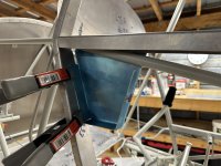
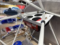
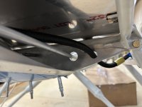
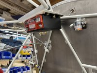
The last item on my goals for this week was to mount the battery box. After a lot of back and forth on battery choice, I've decided on using the Odyssey PC680 to run the starter and com radio. I plan to leave the airplane on a maintenance charger while the airplane sits in the hangar and while the lithium batteries are much safer than they used to be, I don't think I'd be comfortable leaving a lithium battery to charge unsupervised. Between the peace-of-mind that comes with using an AGM battery and the much lower cost, I'm willing to accept the weight penalty. With the firewall space filling up, I looked at alternative mounting locations for the battery box. With the help of my flying/building buddy, Randy, we decided to mount the battery in front of and below the instrument panel on the bottom side of the diagonal braces from the firewall to the fuselage sides. We fabricated a tray from .063" 2024-T3 that is secured to the tubes with adel clamps to which the battery box will mount. A flange was bent on the rear edge of the tray for rigidity and holes drilled to mount the box. After finalizing the mounting and fitment of the tray, the excess material was removed to lighten the part. The battery box will mount to the tray with a combination of 1/4" bolts and Camloc fasteners. This is to make installation and removal of the battery easier while still having the tensile strength of mounting with bolts. The battery can be inserted into the box, the assembly lifted up and secured with 2 camlocs to hold it in place while the 4 bolts are installed. The assembly weighs about 16 lbs so counting on 4G positive loading with 1.5x margin, it needs to support 96 lbs of downward force. This was tested with a force gauge to 100 lbs and showed no signs of deformation, let alone failure. The parts were then removed and prepped for priming. The location allows for convenient routing of wiring and installation of electrical components and saves a lot of real estate on the firewall. I feel that its an ideal spot for mounting the battery and I'm very happy with this setup.

That's it for this weeks progress report. Pictures incoming...
 
A few pictures of this weeks work. Again, I was too preoccupied with building to take many pictures. I’ll try to take more and post them later.
 

Attachments

  • IMG_1791.jpg
    IMG_1791.jpg
    1.7 MB · Views: 1
  • IMG_1788.jpg
    IMG_1788.jpg
    2.1 MB · Views: 1
  • IMG_1787.jpg
    IMG_1787.jpg
    2 MB · Views: 1
  • IMG_1770.jpg
    IMG_1770.jpg
    2.1 MB · Views: 1
  • IMG_1778.jpg
    IMG_1778.jpg
    2.3 MB · Views: 2
  • IMG_1797.jpg
    IMG_1797.jpg
    1.5 MB · Views: 1
  • IMG_1798.jpg
    IMG_1798.jpg
    1.3 MB · Views: 1
  • IMG_1799.jpg
    IMG_1799.jpg
    2 MB · Views: 1
  • IMG_1805.jpg
    IMG_1805.jpg
    2.2 MB · Views: 1
  • IMG_1792.jpg
    IMG_1792.jpg
    1.4 MB · Views: 1
  • IMG_1790.jpg
    IMG_1790.jpg
    2.6 MB · Views: 2
  • IMG_1808.jpg
    IMG_1808.jpg
    2.1 MB · Views: 2
  • IMG_1804.jpg
    IMG_1804.jpg
    1.4 MB · Views: 2
  • IMG_1806.jpg
    IMG_1806.jpg
    1.2 MB · Views: 2
I was out of town several days this past week so progress is limited. Just a few small items to report.

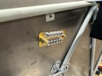
I primed the battery tray, throttle quadrant mounts and the throttle slave rod. After a couple days of curing, I riveted nutplates and Camloc receptacles on the battery tray and reinstalled the assembly. I cut the hole in the oil cooler shroud and riveted on the duct flange and reinstalled that assembly. I installed the battery contactor and a B&C ground block on the firewall and installed a 1" firewall penetration for the starter cable and P-lead wiring. The Tee-fitting for the brake system finally arrived so I installed that and finished plumbing the brake system. This required me to cut holes in the belly former to route the lower flexible brake lines through. I located and drilled the hole for the rigid fuel line to pass-through the former while I was at it. Grommets will be installed in these holes on final assembly. The exhaust tunnel was cleco'd in place so I knew what space I had to work with. I reinstalled the front throttle quadrant and started fabricating a mount to secure the throttle/carb heat cables to. After trying to figure out a way to secure a mounting bracket using Adel clamps to avoid welding, I decided that I didn't like any solution I could come up with so welding it is. I started with a paper mock-up and transferred this to some 4130 sheet for the final part. This was cut-out, bent and checked for fit and function. I hope to get this welded on and the primer/paint touched up this week. I also started playing around with instrument panel layout so I can determine routing of the tach cable, oil pressure/temp lines and primer lines.

Pictures incoming...
 
Pictures from the past weeks progress…
 

Attachments

  • IMG_1844.jpg
    IMG_1844.jpg
    1.6 MB · Views: 2
  • IMG_1821.jpg
    IMG_1821.jpg
    1.7 MB · Views: 2
  • IMG_1820.jpg
    IMG_1820.jpg
    2 MB · Views: 2
  • IMG_1822.jpg
    IMG_1822.jpg
    1.7 MB · Views: 2
  • IMG_1819.jpg
    IMG_1819.jpg
    2.4 MB · Views: 3
  • IMG_1813.jpg
    IMG_1813.jpg
    2.4 MB · Views: 4
  • IMG_1872.jpg
    IMG_1872.jpg
    1.7 MB · Views: 4
  • IMG_1854.jpg
    IMG_1854.jpg
    1.7 MB · Views: 2
  • IMG_1866.jpg
    IMG_1866.jpg
    1.9 MB · Views: 3
  • IMG_1874.jpg
    IMG_1874.jpg
    1.9 MB · Views: 3
  • IMG_1856.jpg
    IMG_1856.jpg
    2.4 MB · Views: 3
  • camphoto_126398554.jpg
    camphoto_126398554.jpg
    2 MB · Views: 2
  • IMG_1879.jpg
    IMG_1879.jpg
    1.6 MB · Views: 3
  • IMG_1855.jpg
    IMG_1855.jpg
    2.3 MB · Views: 3
  • IMG_1875.jpg
    IMG_1875.jpg
    2.4 MB · Views: 4
  • IMG_1878.jpg
    IMG_1878.jpg
    2.3 MB · Views: 2
  • IMG_1877.jpg
    IMG_1877.jpg
    3.1 MB · Views: 2
  • IMG_1880.jpg
    IMG_1880.jpg
    1.8 MB · Views: 3
I really like your 1/4 turn fasteners that hold the battery in place. The packaging of this stuff looks well done to me. Packaging everything (placement of line replaceable units, like battery, solenoids, every firewall penetration, cables, etc) is mysterious, and it seems your doing it very well.
 
A little more progress to report!

Since the last update, I welded the throttle/carb heat cable bracket to the fuselage and touched up the primer and paint. This turned out great.

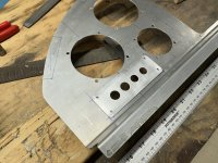
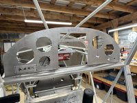
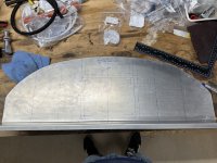
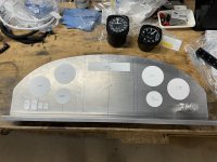
Between coats of primer and paint, I layed out and cut the instrument panel. Of course, I had to test fit the instruments and see how I liked the placement of the buttons, knobs and switches. I’m very pleased with the layout and the ledge along the bottom of the panel is nice for supporting your hand while using the touchscreen of the iPad. The compass in the photos is just a stand-in but everything else is what I plan on using.

I finished all the firewall penetrations for the tach cable, oil pressure/temp lines and primer lines.

Finally, I removed the engine and landing gear so I could cleco the boot cowl and exhaust tunnel pieces to the airplane. The fit right out of the box is pretty good and looks like it will require just a little work to dial in, mostly the top-center cover and the bottom around the exhaust tunnel. This will be my primary focus in the coming week.
 

Attachments

  • IMG_1898.jpg
    IMG_1898.jpg
    1.6 MB · Views: 3
  • IMG_1884.jpg
    IMG_1884.jpg
    2.1 MB · Views: 3
  • IMG_1913.jpg
    IMG_1913.jpg
    1.9 MB · Views: 3
  • IMG_1912.jpg
    IMG_1912.jpg
    2.1 MB · Views: 3
  • IMG_1899.jpg
    IMG_1899.jpg
    2.2 MB · Views: 4
  • IMG_5622.jpg
    IMG_5622.jpg
    1.1 MB · Views: 4
  • IMG_1930.jpg
    IMG_1930.jpg
    1.7 MB · Views: 4
  • IMG_1920.jpg
    IMG_1920.jpg
    1.7 MB · Views: 3
  • IMG_1935.jpg
    IMG_1935.jpg
    2 MB · Views: 4
  • IMG_1934.jpg
    IMG_1934.jpg
    1.9 MB · Views: 4
  • IMG_1882.jpg
    IMG_1882.jpg
    2.8 MB · Views: 4
  • IMG_1932.jpg
    IMG_1932.jpg
    2.2 MB · Views: 4
  • IMG_1921.jpg
    IMG_1921.jpg
    1.7 MB · Views: 5
  • IMG_1936.jpg
    IMG_1936.jpg
    2.4 MB · Views: 4
  • IMG_1937.jpg
    IMG_1937.jpg
    2.1 MB · Views: 4
  • IMG_1938.jpg
    IMG_1938.jpg
    2.1 MB · Views: 3
Oh yeah they’re great! A single point ground makes a huge different in the quality of audio in your headset. Highly recommend them.
 
Thank you, Brooks. The Camlocs on the battery box are just to hold the battery and box in place while the bolts are installed. Being mounted on the bottom of plate would make it tricky to hold in place while lining up and starting bolts. The bolts are necessary to bear the weight of the battery up to +4G. I’m a full-time aircraft mechanic so I like to make things maintenance friendly.
 
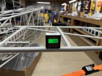
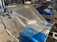
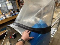
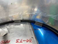
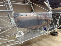
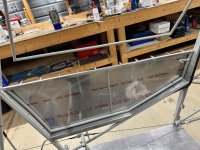
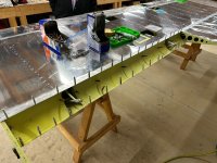
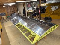
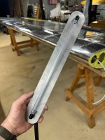
Haven't posted in a while but work on the LSA is progressing steadily. Since my last post, I finished fitting and drilling the boot cowl, installed the windshield and laid-up the windshield fairing, skinned the door and built-up the windows (what a job that was!). With most of the pre-assembly work complete on the fuselage, I turned my attention to the wings. The wings were a pretty straight forward and work progressed fairly quickly. With both wings completed, I moved my Cub to a friend's hangar to make room for the LSA in preparation for wing installation. This was necessary to finish fabricating aileron cables and sorting out the wing-to-fuselage fuel connections. With the help of my dad and my friend Randy, wing installation went well. The factory drilled spars lined up perfectly and appear to be properly located after checking wing incidence with a smart level. I also reinstalled the tail feathers to check the rigging one last time before covering. The horizontal stabilizer struts that came with my kit were too short to rig the tail correctly so this gave me a chance to check the fit of the reworked struts from Bearhawk Aircraft. All worked out well and after a little tweaking, all the flight controls were fully rigged. I used turnbuckles that were drilled for safety clips so that I wouldn't have to safety wire the aileron turnbuckles through the inspection panels. I can't recommend this enough. I'm happy with how things are going and seeing the airplane assembled has been incredibly motivating. In the coming weeks, I'll be removing the wings and reinstalling the engine in preparation for fabricating the cowling. Pictures will be posted here a few at a time in separate posts.
 
Here are some pictures of the boot cowl/ windshield install.
 

Attachments

  • IMG_2368.jpeg
    IMG_2368.jpeg
    788.8 KB · Views: 9
  • IMG_2380.jpeg
    IMG_2380.jpeg
    969.5 KB · Views: 9
  • IMG_2382.jpeg
    IMG_2382.jpeg
    794.1 KB · Views: 8
  • IMG_2426.jpeg
    IMG_2426.jpeg
    894.4 KB · Views: 8
  • IMG_2431.jpeg
    IMG_2431.jpeg
    830.6 KB · Views: 8
  • IMG_2442.jpeg
    IMG_2442.jpeg
    1.2 MB · Views: 6
  • IMG_2486.jpeg
    IMG_2486.jpeg
    738.3 KB · Views: 7
  • IMG_2586.jpeg
    IMG_2586.jpeg
    467.5 KB · Views: 6
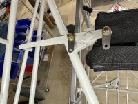
Door and windows
 

Attachments

  • IMG_2786.jpeg
    IMG_2786.jpeg
    874.2 KB · Views: 12
  • IMG_2798.jpeg
    IMG_2798.jpeg
    1 MB · Views: 10
  • IMG_2799.jpeg
    IMG_2799.jpeg
    786 KB · Views: 9
  • IMG_2818.jpeg
    IMG_2818.jpeg
    685.7 KB · Views: 9
  • IMG_2832.jpeg
    IMG_2832.jpeg
    882.1 KB · Views: 9
  • IMG_2838.jpeg
    IMG_2838.jpeg
    1 MB · Views: 9
  • IMG_2887.jpeg
    IMG_2887.jpeg
    1 MB · Views: 9
  • IMG_2896.jpeg
    IMG_2896.jpeg
    1,021.3 KB · Views: 9
  • IMG_2931.jpeg
    IMG_2931.jpeg
    744.6 KB · Views: 9
  • IMG_2933.jpeg
    IMG_2933.jpeg
    714.8 KB · Views: 9
Wings
 

Attachments

  • IMG_2955.jpeg
    IMG_2955.jpeg
    926.7 KB · Views: 11
  • IMG_2966.jpeg
    IMG_2966.jpeg
    826.3 KB · Views: 11
  • IMG_3002.jpeg
    IMG_3002.jpeg
    541.5 KB · Views: 9
  • IMG_3049.jpeg
    IMG_3049.jpeg
    619.4 KB · Views: 11
  • IMG_3171.jpeg
    IMG_3171.jpeg
    618.8 KB · Views: 11
  • IMG_3170.jpeg
    IMG_3170.jpeg
    750.3 KB · Views: 14
  • IMG_3172.jpeg
    IMG_3172.jpeg
    601.2 KB · Views: 13
  • IMG_3183.jpeg
    IMG_3183.jpeg
    875.8 KB · Views: 11
  • IMG_3285.jpeg
    IMG_3285.jpeg
    943.7 KB · Views: 11
  • IMG_3339.jpeg
    IMG_3339.jpeg
    999.5 KB · Views: 12
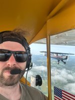
Wings and tail installed on fuselage! Plus a bonus flying pic
 

Attachments

  • IMG_4088.jpeg
    IMG_4088.jpeg
    1.1 MB · Views: 18
  • IMG_4089.jpeg
    IMG_4089.jpeg
    1.1 MB · Views: 13
  • IMG_4091.jpeg
    IMG_4091.jpeg
    1.2 MB · Views: 13
  • IMG_4090.jpeg
    IMG_4090.jpeg
    643 KB · Views: 13
  • IMG_4094.jpeg
    IMG_4094.jpeg
    1.1 MB · Views: 14
  • IMG_4098.jpeg
    IMG_4098.jpeg
    621.7 KB · Views: 14
  • IMG_4111.jpeg
    IMG_4111.jpeg
    1.2 MB · Views: 14
  • IMG_4081.jpeg
    IMG_4081.jpeg
    570.2 KB · Views: 16
  • IMG_4096.jpeg
    IMG_4096.jpeg
    682.4 KB · Views: 18
Back
Top