Notes on Forming Patrol Wing Ribs (Plus Side-Bar On Rib Fit to Spars)

SpruceForest

Scratch-Built Patrol SP
I like After Action Reviews… they are usually structured something like: “What was supposed to happen, what did happen, good stuff, bad stuff, and how to make the ‘supposed to’ and ‘did’ line up next time.” I consider these reviews to be just as important to a homebuilding project as a military operation, and I suspect – judging from the number of ‘here’s how I did that’ videos on YouYube – others do as well. These notes are an attempt to provide some lessons learned along the way to producing the 160 airworthy ribs needed for a Patrol wing. The usual caveat applies: what worked for me may not work for anyone else. Buy some extra aluminum in anticipation of trialing methods and tweaking the process to make them work FOR YOU, though, should you choose to run with any of these methods, and certainly before committing to production.

If these notes appear to duplicate various ‘here’s how I did it’ docs and builder site posts, consider it an endorsement of that particular technique and a shout out of ‘good on you!’ to the authors. I apologize ahead of time where I have failed to give appropriate credit where due (e.g., the inventor of the VAF flange straighter is still unknown to me, so I credited the site, instead), and feel free to drop me a message or email. Also note that this is not a step-by-step exposition, but instead a collection of notes on what worked and what needed some tweaks. Maybe someday…

Finally, the choices I made on tools and methods had as much to do with what worked as my own background and skill set. There are a lot of ways to get this stuff done, but methods that were extensions of my approach to woodworking and guitar building (mixed hand and machine methods) seemed most comfortable for me. Take these notes as one more set of data points to be used…or further tweaked!

For those that prefer to avoid navigating through an
archipelago of posts, the PDF is attached.

Note: the title of the thread was adjusted due to some drift in topic and the need to keep things as searchable as possible for members.
 

Attachments

Last edited:
Process for Routing Rib Blanks:

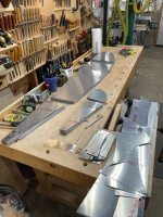
- Roughing out blanks was straightforward – just snip work after the rough processing of the 4x8 and 4x12 .020”, .025”, and .032” sheet stock into more manageable sizes with track saw and tablesaw. I optimized layout with a half scale set of templates and got at least the required number of ribs (all 160!) out of the initial sheet stock order, but in retrospect, adding an extra sheet of .025 to the initial order would have provided more in the way of material for trialing methods and all those stiffeners that are needed after the ribs get pressed.

Click image for larger version  Name:	image_11790.jpg Views:	78 Size:	95.8 KB ID:	74977

- MDF worked well for form and template blocks…I hardened with super-thin BSI and Satellite City Hotstuff CA (18 ounces!!!), but also used some Minwax and Varathane wood hardener where I just needed some protection against water intrusion (as on the form block covers).

- To keep all jig pin holes referenced to the MDF master wing rib section, all routing template jig pins were marked with transfer punches using bench dogs to keep things from shifting during marking. Using the same approach for marking the rib blank from the template worked well, with only one rib that showed some drift during marking (~ 0.005” on one nose rib hole…no clue how it happened, but it did). I found out that avoiding any slip in the template was a priority. The jig pin holes were NOT deburred beyond reaming with a 0.251” reamer so as to maintain maximum contact area with guide pins and machine screws, with final cleanup done only after forming and clean-up.

- All jig pin holes were drilled to ¼” using a centering bit and then reamed to 0.251 … these bits don’t walk like a split point might do and come close to a reamed hole in terms of quality. Finishing with a reamer is likely overkill, but it does a nice job of squaring and smoothing.

- I tried several methods to mill out the lightening hole excess prior to routing, to include pilot hole and snips (just because I really, really wanted to time the process…slooowww), fly cutter in drill press, and what I eventually found was the easiest and fastest approach – an air nibbler guiding on the template with blank installed. Once the blank was roughed and drilled for jig pins, I loaded it in the template-and-routing-cover-plate sandwich, piloted the lightening holes with a ¾” step drill bit, then removed the waste to within about 3/16” of the edge of the template. The nibbler head – with a cylindrical, smooth cross-section - references the edge of the template and provides a very smooth cut. As a bonus, the waste is large enough to get all the flap and aileron rib attachment angles out of, as well as some 0.025” and 0.032” scraps of 5” diameter or more and no drill press center hole, for small jobs.

- I did this in an area of my back yard adjacent to my deck that was getting scraped and filled with 3” of pea gravel in a week or so, but better done where the sharp little quarter (moving too fast) and eighth moon-shaped waste will not end up in children’s or animal feet… the shop is not a bad place if you can keep the debris corralled to a small area (I used poly/paper laminate drapes around the router table to keep all that aluminum in one place, and that would work for the nibbler work as well). Also note that these little bits of debris can fly a fair distance, so eye protection and the usual additional body protection is a must…I routinely wear ANSI A3 level anti-cut handwear, long sleeved shirt or welding sleeves, a flip-down face shield, and work pants with cuffs to roll down over my boots to avoid all that sharp aluminum swarf and cutoffs.

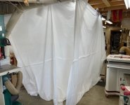
Click image for larger version  Name:	RouterTableDrapes02.jpg Views:	0 Size:	60.5 KB ID:	74979Click image for larger version  Name:	RouterTableDrapes02.jpg Views:	0 Size:	60.5 KB ID:	74979

- I used Glen Patterson’s ‘Making Tool and Die for Wing Ribs With a Router’ methods document as a guide for routing those complicated flap nose ribs and aileron pocket and nose ribs, as well as the cleanup routs on the forward edge of the nose rib flanges. Glen’s method used equipment commonly found in well-equipped woodworking shops – router table, bushed insert, etc., so this worked quite well with just a change from aluminum to wood for the steering/gripping handles. On the main wing ribs (nose, center, tip, stub) and the aileron and flap ribs, I used an approach similar to standard woodworking pattern routing, with single layer MDF routing templates with flanging allowances and a single layer cover.


Click image for larger version  Name:	FlapRibs01.jpg Views:	0 Size:	112.9 KB ID:	74981

- The chamfer on the form block lightening holes took a bit to get right, and what worked for my soft hardware store aluminum stock was not what worked for 2024-T3. For the main wing ribs in 0.025”, I found that a 45 degree chamfer of .525” width on the form block resulted in 30 degree flanges of 0.375” width. Note: this is the actual, measured width of the chamfer, versus the plan view width. On the aileron and flap ribs, a .375” chamfer width gave me 30 degrees and .250” flange width. The graphic below provides the measurement and application.

Click image for larger version  Name:	FlapRibs01.jpg Views:	0 Size:	112.9 KB ID:	74981
 
Last edited:
Prep for Rib Pressing:

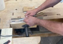
- After routing, all of the straight/gentle curve edges were cleaned up with a chalked 8” and 10” mill bastard file (I used a sharp 8” US-made Nicholson file and clean every few ribs with a file card…chalking helps), 320 sandpaper on a quarter-sheet-sized block (18mm plywood with radiused long edges with 1/16” cork facing). A quick pass over the 6” 3M medium/firm and fine/softer wheels removed any scratches and put a little more radius on the edges where filing had sharpened things up.

- Lightening hole edges were cleaned up with cylindrical sanding blocks (dowel sections or cork-faced CPVC pipe). A sheet of 320 lasted through a dozen ribs, and was quite fast at knocking down irregularities and router chatter.


Click image for larger version  Name:	EdgeSandingRibs.jpg Views:	67 Size:	30.8 KB ID:	74984​ Click image for larger version  Name:	EdgeSandingRibs.jpg Views:	67 Size:	30.8 KB ID:	74984

- A 1” x 1” 3M non-woven drum-on-mandrel and a 2” x 1/8” disc-on-mandrel mounted in a couple HF Chief-branded mini die grinders, as well as some 1/8” x 3” x 1” sanding blocks with radiused edges were used to clean up the interior cuts (lightening hole sand deep cuts on the smaller flap and aileron ribs)… 320 paper works and does not leave scratches that are deep enough that they will not be removed with some non-woven abrasive use. I use the Festool Granit stuff for guitar work in P150/P220/P320 – reasonably priced at about $42 for a sleeve of 50 sheets and just as effective on aluminum as on wood).

- All ribs got 3M maroon pad cleanup before forming, which was enough to deburr IF PRIOR CLEANUP HAD BEEN DONE WITH FILE, SANDPAPER, ETC. This fine-grit pad is not a shaping tool – it refines and smooths what is already present. Where I started with lumps and bumps, I ended with smoother lumps and bumps. Starting the process with a shaping tool to generate a faired edge was much more effective at eliminating potential stress risers. Cutting the pads into quarters, then quartered again (16 pieces from the pad) worked, and one of those small pads per rib (three on the tip ribs…lots to do) worked. I buy these pads in boxes of 20 for about $26, and figure 3-4 boxes might get me through the entire project. Cleaveland also has a little mandrel that can take a piece of maroon pad for use as a sort of flap sander… nice for paint prep.

- All ribs were labeled for flange side and non-flange side. I used a consistent ‘(LH/RH), (component), (Flange This Side/This Side Not Flanged)’ notation and still managed to make up a few extra aileron ribs, which suggests that having a single-sided press block is a good idea (and hide the other-handed block until all the same-hand ribs are pressed). Also important to get the forming sandwich in the press in the correct order.
 
Last edited:
Tooling – Press Stack and Materials

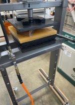
- The HF 20 ton press with the usual mods (HF hydro-pneumatic 20 ton jack add-on, ¾” press plates, HD locking casters, press plate suspension system, etc.) works well for the press job. A 50 ton press with a full-sized rubber press set-up would be better, but that moves the cost such that it would have to be justified across a number of builders.

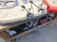
Click image for larger version  Name:	RibPressAndFormBlockSandwich.jpg Views:	0 Size:	93.3 KB ID:	74988

- Pledge contains silicone, which is difficult to remove and messes with more traditional finishing systems like enamels and lacquers (think fisheye/failure to bond), but I used it after isolating application to just the press area. WD-40 works about as well and is silicone-free, but the solvents take a toll on the protective plastic (as does Pledge… I routinely saw film delamination on the non-flanged side of lightening holes). That said, there is a need for some sort of lubrication to allow the urethane pad to slip a bit, as well as break the adhesion between pad and formed rib, which is pretty good from what I saw when I forgot to spritz the aluminum prior to forming.


Click image for larger version  Name:	RibPressAndFormBlockSandwich.jpg Views:	0 Size:	93.3 KB ID:	74988

- Using machine screws for template-to-cover plate rout alignment worked OK, but for flow forming and press work, any side load on the blank can cause slippage against those sharp screw edges. Shop-made jig pins made from left-over-from-Lancair 235 build AN4 (0.249”) close tolerance bolts worked better to lock things in place and protect the accuracy of alignment between form block and blank through the end of the forming process. I ground the bolt heads down to 0.070” thickness on the 6” x 48” stationary belt sander, lightly domed them to protect the urethane press pad from cuts, ground the head to a circle on the 12” disk sander, trimmed the unthreaded portion of shaft to desired length with a hack saw (0.7/1.4/2.1 inch for 1, 2, and 3 layers of MDF), broke all edges, then buffed out the head and shaft on the 8” low speed buffer with sewn wheels and medium Menzerna dry polishing compound we use for guitar fret work.

Click image for larger version  Name:	RibPressAndFormBlockSandwich.jpg Views:	0 Size:	93.3 KB ID:	74988

- Press stack was originally 0.75” x 12” x 12” cold rolled steel plates top and bottom, 1” x 12” x 12” urethane sheet (McMaster-Carr PN 8789K81, as recommended by John Snapp, aka N3UW), 0.375” x 12” x 12” neoprene sheet (this is transition sheet between urethane and the recycled large animal mats), and 2 x 0.75” x 12” x 12” recycled rubber stall mats. This stack gave me good performance on pressing out the 0.025” sheet lightening hole flanges on the single ply form block main wing ribs, but getting to 75-80 degrees on the aileron and flap rib edge flanges took two additional changes: going to a 1.5” thick form block and addition of two more sheets of 0.75” stall matting. The downside of that change was that the two layers of stall matting closest to the form block (below urethane and neoprene sheets) take a beating during the press cycle. Eventually, the stall matting fractures and needs to be replaced. With the deeper stack, I was getting 77-78 degree flange bends, which made sense given the 12 degree overbend needed on the flange straightener.

- The ideal stack would be three pieces of the McMaster-Carr 1” urethane sheet, but at $154 for each piece of additional urethane versus $55 for 24 pieces of stall matting and $20 for a neoprene barrier, a $280 savings balanced out the 10-12 pieces of matting nuked getting through the 160 ribs in a Patrol, and just about paid for the press and 20 ton air jack on sale at HF. I should mention that the urethane sheet is incredibly durable…even with all those sharp edges at the corners of aileron and flap, and some truly impressive distortion, other than some light surface scuffs, no tears or other significant damage. Thus far, no need to even flip the urethane sheet over, with the tip ribs and the little stuff to go (flap nose and aileron nose/pocket ribs)
 
Last edited:
Tooling and Process – Form Blocks

- I started off using single-layer MDF press blocks for everything and only building up two-layer blocks for flow forming, but found that – while that worked really well for the lightening hole flanges - the edge flanges needed more block depth as well as a deeper stack to fully form as detailed above. One issue with those deeper blocks is that leaving all those lightening hole openings unfilled results in a fair amount of that applied 40,000 pound press load going into deforming the urethane press pad to fill those openings…which does no useful additional work as the lightening hole flanges have already been formed by that point in the press cycle. I ended up redoing the form blocks for those ribs I wanted to fully press, adding an additional layer and a 0.375 inch filler piece that rested on the bottom layer to close the lightening hole recess. I flow-formed all the center and stub ribs, but used two-layer form blocks on the following: nose and tip ribs; aileron, aileron nose, and aileron pocket ribs; flap and flap nose ribs. I should mention that I took a shortcut and mounted the left and right flap and L/R aileron press blocks back to back versus fabricating new back layers, but it then becomes quite a bit easier to press an unwanted extra left or right. As mentioned earlier, I tried to avoid having more than the specific set of blanks and the proper form block on the bench at any given time.

Click image for larger version  Name:	CompletedRibPress.jpg Views:	0 Size:	46.6 KB ID:	74990
- For ribs that were flow-formed (all center, stub, and the center section of the tip ribs), to be flow-formed, a two-layer, reversible form block worked well, with the already-pressed lightening hole flanges on the 0.025” ribs minimizing any potential confusion on which side to form. I used the same Bessey K-body clamps that John Snapp shows in his videos to clamp the forming block, cover, and blank to the bench… the K-Body is a woodworker’s staple clamp for panel glue-ups, but even guitar makers that seldom glue up large panels usually have some of these stashed away for jig and fixture work! The ATS short and long flow-forming head with nylon tips were used, with the shorter length tool working best for my #4 rivet gun.

- The edge flanges on nose ribs were a challenge. I trialed the following variations:

o Pressing the edge flanges and lightening holes at the same time with a single layer form block and two-layer block

o Hybrid forming (press lightening holes, then flow forming the edge flanges)

o VAF-style flange straightener before fluting and after fluting

- Pressing all flanges on the nose ribs gave me the best profile and avoided beating up the 4t radius transition at the forward end of the edge of the flanges. Worth having a radius gauge for checking after forming and working the rib…although I radiused form blocks and my tweaking tool for 0.100”, staying off the ends of the edge flanges during straightening and tweaking was necessary to avoid tightening that radius. I rejected any ribs where bend radius was less than a smooth 0.080”/3t after working, with that forward end of the nose rib flange an area of interest.

Click image for larger version  Name:	FlutedFlangedNoseRib.jpg Views:	0 Size:	79.9 KB ID:	74991 image_11803.jpg
- Edge flanges on the center, stub, and center portion of the tip ribs were quicker to do with the flow-forming head and some light dead-blow hammer work. These flanges were worked with the flange straightener BEFORE fluting, although the difference between fluting before and after using the flange straightener was pretty minor.

FlutedFlangedCenterRib.jpg
- I left the protective plastic on the ribs, assuming it would be a stand-in come dry assembly time for the film thickness of the primer coat. This is still an open issue in my mind, but it does minimize scuffs and dings which need working over prior to shooting primer.
 
Last edited:
Flange Straightening After Pressing & Flow Forming

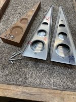
- I fluted immediately after pressing on the nose ribs and nose section of the tip ribs, then worked with the VAF-style flange straightener around those flutes. A pair of modified Channel Lock 317 long nose pliers with about half the snout trimmed back past the serrations and the ends radiused to 0.10” with corners broken, then taped does a nice job of straightening out the remaining lumps and bumps after pressing, fluting, and flange-straightener.

Click image for larger version  Name:	FluteAndTweakTools.jpg Views:	0 Size:	57.1 KB ID:	74999
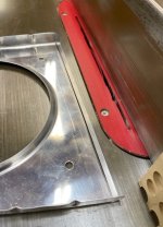
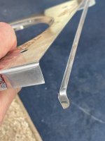
- The VAF-style lever-action straightener worked well once modified with a 12 degree face (versus 11 degree) and some reshaping of the lever to trim away the heel to allow access to the areas around the lightening holes and the trailing edges of the tip, aileron, and flap rib. I also trimmed the face to a width of about 7/8” for some ability to work along the slight curves between flutes. The 12 degree face angle on the anvil block gave a consistent 90 degree flange in 2024-T3 for the preferred sheet stock grain direction. And note the end was radiused to 0.1", although it is necessary to touch that up as the tip wears to avoid any flats in the transition from rib face to flange.

Click image for larger version  Name:	FluteAndTweakTools.jpg Views:	0 Size:	57.1 KB ID:	74999Click image for larger version  Name:	FluteAndTweakTools.jpg Views:	0 Size:	57.1 KB ID:	74999Click image for larger version  Name:	LeverTipSideViewVAF_FlangeStraighterner.jpg Views:	0 Size:	52.0 KB ID:	75000 Click image for larger version  Name:	FluteAndTweakTools.jpg Views:	0 Size:	57.1 KB ID:	74999

- The jig pin holes on some of the 160 ribs were a bit beaten-up by the end of the routing and forming process, so the ATS offset deburring tool was used to chamfer and clean the edge holes, then the small pyramidal 3M non-woven, compressed shop-made tip for the Dremel threaded mandrel was used to polish and clean things up. This same tool can be used to clean up the tight radius slot bottoms on the flap nose and aileron nose and pocket ribs. Creation and use of this tool is detailed in Plane Lady’s YouTube video (https://youtu.be/Tp6kyKN2s3o). This was a good tool for cleaning up the jig pin holes, as well as those complex contours at the forward end of the nose rib flanges. One 2” 3M wheel provided a couple airplane’s worth of tips, and can be reshaped on a belt sander for a custom fit to the job. I kept mine mounted in the Foredom tool hanging above one of my benches, and extended the shaft with an add-on VOTOER ‘universal flex shaft adaptor’ from Amazon.
(
https://www.amazon.com/gp/product/B0...?ie=UTF8&psc=1)
 
Last edited:
The End Note

The philosopher-craftsman David Pye wrote about the workmanship of risk in craft back in the late 1960’s. Pye defined that as "workmanship using any kind of technique or apparatus, in which the quality of the result is not predetermined, but depends on the judgment, dexterity and care which the maker exercises as he works" (The Nature and Art of Workmanship, p. 4). To restate, the difference between risk and the ‘workmanship of certainty’ was in the likelihood that the workpiece might be trashed by a momentary mental or physical lapse using a method reliant on high skill/high focus… versus a method which relied on additional process and jig/fixture design to generate a completed, acceptable workpiece with less operator skill and judgement required. Pye noted that the workmanship of risk often produced artifacts more artistically interesting than the workmanship of certainty… he saw those tell-tale artifacts of the maker’s hand adding up, creating visual and tactile interest not present in factory or mass-produced objects.

While I find that concept interesting from the viewpoint of something like a one-off custom guitar, the concept of workmanship of risk seemed intuitively less attractive when applied to the job of turning out 160 wing ribs to be wrapped in aluminum, hidden from view, and all done with the intent of conveying my behind from Point A to Point B without unintended levels of excitement. In general, I steered in the direction of higher certainty and lower risk in the methods used, so for those looking for guidance on accomplishing the wing rib task with sole use of snips, file, dead-blow hammer, and bit-and-brace, you may be better served looking elsewhere for guidance.
 
Last edited:
We cut 2024 blanks at various angles relative to the 2024 sheet grain. I believe that causes some very small variation in the bends from rib to rib. I never pre cut my ribs for spar caps. I found it best to sort each rib for the placement along the spar. The spar has variation along the length and different ribs will fit better at different locations. Only then did I trim for the cap strip notches.

One additional thing I did was make multiple mdf blanks with the slightest variation for the final placement along the spar. If a specific rib needed a small adjustment I would select a slightly different mdf form to modify it. I just put it back under the 20 ton press again.

I found a special bearing that allowed me to quickly make the various mdf form blocks. The bearing is 0.010 under size. Using the first mdf form I could make another mdf form that is 0.020 smaller. If necessary that form block could be used to make another block that is 0.040 smaller.

Click image for larger version  Name:	routerbearing.jpg Views:	0 Size:	12.3 KB ID:	75005

I also purchased one inch thick mdf. It is not available from lowes or home depot. It is the sort of thing that can be purchased at a cabinet shop. One form could be used for left and right ribs.
 
Last edited:
I think this rib trimming thing is one of those processes where there must be tons of options that actually work... I've seen a couple so far, and they all produce an accurate trim. After toasting one or two blanks getting to an airworthy nose rib, I trialed a tablesaw method on 1/8" and 1/4" (shown) cuts:

1. Determine how much to trim

2. Make sure the flanges are flush with the spar face

3. Set the tablesaw fence to the desired measurement, and the 7-1/4" Freud Diablo 40 tooth blade to about 0.080-0.10" height

4. Back the rip cut with scrap MDF to prevent chatter, keep control of the soon-to-be-offcut, and control the chips (the MDF sits over the blade inside the rib and against the fence)

5. After the first cut, trim the flanges with aviation snips and clean up the edge on wheel/by hand, etc.

IMG_3510.jpgRibTrimFirstCut.jpgRibTrimFlangeCuts.jpgRibTrimComplete.jpg

Takes longer to talk about than to do it, and works on any rib that has a flat edge against a spar.
 
Actually, I was recommending something different:

Click image for larger version  Name:	trim.jpg Views:	0 Size:	159.5 KB ID:	75012
All that is required is a notch. There are three advantages to not trimming:

1) You get extra rivet edge distance for all but the rivets over capstrip.
2) That edge that was made from your mdf is a nice reference edge.
3) The spar is not perfectly the same at each station. The ribs are not all identical. If you do not trim you can put the rib that fits the main spar best as an average over entire spar.

I choose to assemble on a table. Since all of my blanks came from the same mdf form they all had parallel edges. Those edges are also the exact distance apart.
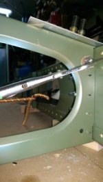
I used wood spacers to space up the rear spar and bungee cord to hold the rear spar and main spar tight against the center ribs - which had parallel sides.

Click image for larger version  Name:	assemble.jpg Views:	0 Size:	19.4 KB ID:	75014
Click image for larger version  Name:	all.jpg Views:	0 Size:	184.0 KB ID:	75015
 

Attachments

  • assemble.jpg
    assemble.jpg
    19.4 KB · Views: 1
Last edited:
I think the correct distance to space up the rear spar is 1.34 (patrol only) inches. Any other number would not yield parallel sides of the center rib.

Click image for larger version  Name:	one.jpg Views:	0 Size:	136.7 KB ID:	75017
 
Last edited:
The attach holes for the main spar and the rear spar are not concentric. When the wing is moved to a vertical stand there should be an offset - as shown with plumb bob.
The offset is 1/2 inch
Click image for larger version  Name:	half.jpg Views:	0 Size:	80.9 KB ID:	75019


When wing was assembled on a table I mocked up a sharpened drill rod going thru the main spar attach hole and convinced my self that
it was 1/2 inch above the rear spar attach hole.

The table is level. The drill rod is level. The rear spar is spaced up 1.34 inches. the spars are perpendicular to table. the center ribs have parallel edges.

The only degree of freedom is the center rib has to be tangent to the spar flange. This was controlled with scrap aluminum that made sure
that there was a smooth transition.

drillrod.jpg
 
Last edited:
So we have folks that trim before forming, those that trim after, those that trim to minimize material. those that notch out to maximize material... that's what I mean about multiple approaches to the same task.

Back when I was an undergraduate flight instructor teaching Euro-NATO and allied ME/FE students, we used to talk about 'filling the toolbox' with different presentations and demos to address differences in background and education. We knew what each allied force used for pilot selection criteria (in the case of one country, pure royal nepotism... lots of 'recycled frequently and without prejudice'), so had an idea on which tools might work for which groups of students, but there were always surprises in how they thought about task execution. Interesting that - given the identical task - we saw a variety of teaching techniques yield success, and some pretty significant differences in execution when the task was not purely mechanical muscle memory or EP immediate action steps. Same thing here... toolboxes being filled up with techniques - loving it!

Looking forward to moving on to spar bending and assembly... cap strips should ship from Spruce-Georgia any day now, and that gets me moving on a whole new set of jobs to do.

Todd
 
So we have folks that trim before forming, those that trim after, those that trim to minimize material. those that notch out to maximize material... that's what I mean about multiple approaches to the same task.

Back when I was an undergraduate flight instructor teaching Euro-NATO and allied ME/FE students, we used to talk about 'filling the toolbox' with different presentations and demos to address differences in background and education. We knew what each allied force used for pilot selection criteria (in the case of one country, pure royal nepotism... lots of 'recycled frequently and without prejudice'), so had an idea on which tools might work for which groups of students, but there were always surprises in how they thought about task execution. Interesting that - given the identical task - we saw a variety of teaching techniques yield success, and some pretty significant differences in execution when the task was not purely mechanical muscle memory or EP immediate action steps. Same thing here... toolboxes being filled up with techniques - loving it!

Looking forward to moving on to spar bending and assembly... cap strips should ship from Spruce-Georgia any day now, and that gets me moving on a whole new set of jobs to do.

Todd

I am creating the formblocks for my Five now and greatly appreciate the different approaches and information shared. As you said, more tools in the toolbox.

Many thanks to everyone who has taken the time to share their approach and tips.

Bill
 
Good luck, Bill...all that MDF creates a really messy shop, but once done you have it behind you and the 'making real airplane parts' stuff ahead! My templates and forms will def make some really cool wall hangings for the pilot-cave/hanger some day! Still noodling an M-14P Bearhawk 5 after the Patrol... hope the engine factory survives.
 
Bob recommends gluing mylar to 032. The mylar has parallel lines representing spars.
I used a table saw to cut mdf with parallel sides that were 32 -0.032 (patrol spar center line is 32 inches apart).
I then layed mylar on top of parallel side mdf.
The parallel lines can be lined up and over the parallel sides of the mdf .
They should be exact match.

Drill the tooling holes to forever match the mylar template with the mdf form.

I would recommend the tooling holes to be a little distance away from spar. I am trying to make sure there are no future issues with rivet to edge distances.
image_11818.jpg

I use the word parallel to emphasize how the parallel sides are of use during assembly


image_11022.jpg Those parallel sides are at right angles to the table during the assembly phase.

​​​​​​
Rough mark the top and bottom of the airfoil. Use a jig saw to cut close to the edge. Routers only can take off a little at a time.

After routing - the mdf form has two parallel sides that are exact, and two routed sides that follow the mylar - aluminum template.

I even made mdf forms that had notches for the flutes.
In the picture below form block 3 has two dowel pins holding aluminum horizontally. The rubber holds aluminum down.
Using a wood dowel flutes can be made. The assembly is held firm with the press.

LIke Spruceforest above a lever can be used to make sure flanges are 90 degrees.

Click image for larger version  Name:	notches.jpg Views:	0 Size:	251.1 KB ID:	75033

Fluting pliers will work. You will find that the first rib will take an hour to flute. Once you get the hang of it , it will only take two minutes.


Consider investing in a company that makes mdf:

mdf.jpg
 

Attachments

  • parallel.jpg
    parallel.jpg
    93.9 KB · Views: 0
  • tool.jpg
    tool.jpg
    294 KB · Views: 0
  • image_11819.jpg
    image_11819.jpg
    251.1 KB · Views: 0
  • notches.jpg
    notches.jpg
    251.1 KB · Views: 0
  • image_11819.jpg
    image_11819.jpg
    251.1 KB · Views: 0
Last edited:
I'm just starting a Patrol scratch build and am planning my manufacturing process for the wing components. I have a stupid question regarding bend dimensions on the wing rib flanges. What are the finished dimensions on the bent flanges meant to be?

On drawing 3 Bob specifies 9/16" flanges bent at 90 degrees however, in the booklet he recommends offsetting the rib form profile by 9/16" from the form block to draw the flat pattern for the ribs. In this case, the bent flanges would be slightly less than 9/16" due to the material consumed in the bend. Furthermore, I don't see bend radius specified for the rib flanges, although I would assume it would be the same as that of the spars at 0.1".

Thanks for posting your notes and Youtube videos of your build! They've been a great resource.

-Lane
 
I found this youtube video:
https://www.youtube.com/watch?v=h9fxo95D4Ik

a number 7 drill has about the right radius.


anyways the radius chamfer is a short cut , a square edge is longer distance.

If anything, the flange would be the tiny bit longer then 9/16 if you use the washer trick.
 
Last edited:
The question we all get stuck on is :

Are you supposed to cut the master template on the inside or the outside of the line.

The answer is neither . It is the middle of the line.


Also I like the spray on 77 for attaching the mylar to a piece of 032.
77.jpg

I cut to the outside of the line and slowly file to the middle of the line. You must leave some of the line.
Others might do it differently.

I also am very fond of 1 inch mdf as compared to the 3/4 inch stuff


As a rule we all start out with O.C.D. You have to remember we are building the wing with a plastic mallet.

hammer.jpg
 

Attachments

  • hammer.jpg
    hammer.jpg
    1.4 MB · Views: 0
Thanks for your reply Stan. That's all good information and clears things up for me. I realized I had gotten things mixed up with the bend acting as a shortcut, it makes sense the way you explained it.

How did you set the bend radius? I suppose one option would be to router the edge of the form block with a router using a 0.1" radius bit. In Bob's booklet he indicates setting a radius but doesn't give a dimension. The only radius dimension listed is on the wrong side of the from block and at 1/32" which would be too tight for the material:

image.png​

I'm also realizing the OCD needs to take a back seat to practicality at times. Maybe I'm overthinking this. Thanks again for your input.

-Lane
Alexis Creek, BC
 
If you buy the 1 inch sheet, you can make one form block instead of two. You can use both sides for forming left and right versions of the wing rib.
No need for a router just round off the hard edge with a sanding block.

Some times Bob says things that might mean something different that what you think.
I would take the 1/32 as an absolute minimum Not as a goal.
Another example is he gives the decimal distance for rivet spacing (1.021 inches). What he real means is 12 rivets in the 12 1/4 inch rib spacing. You need to make sure that the rib locations are 12 1/4 inches apart. And by the way you use 12 rivets. Get the 12 1/4 locations right. And then maybe use a rivet fan or a ruler.


I would buy a 4x8 sheet of quality 1 inch mdf from a store that sells hardwood (oak) and cabinet maker supplies. You will need every bit of a 4x8 sheet for making the form blocks.
Use some cheap 3/4 inch mdf (lowes or home depot or Canada equivalent) for things like the Backup block that holds the material still while whacking it.​


mdf.jpg

I might have used a router on what Bob calls the backup block. I wanted to hit with the plastic mallet with a glancing blow.

I used a flexible ruler and a rivet fan for rivet locations along rib.

Bob says he wants a 1.5 inch spacing. So I figure how many rivets are used to to span the distance between the center of the C-web Spars. The number of rivets is what ever it takes such that the distance between rivet holes is about the 1.5 inches. Not exactly 1.5 inches.
fan.jpg
​
 
In some ways it is harder to make an airplane by hand if you grew up around a machine shop.

The truth is we use rubber mallets to make the wing. Sometimes I have been known to use a wood stick.

For me, I control the accuracy of my measurements by using a single tape measure. I hide the tape measure from my son so he does not use it as a hammer.

For the patrol the ribs are spaced 12 1/4. This single tape measure sets the 12 1/4 rivet distance across the entire spar. I will try to get the in between rivets right because I have OCD but
it does not matter. A rivet fan could have done the job with the required precision.

Is my tape measure accurate? Don't know. I do know I use it in the same way for front and rear spar and that is all that is important.

tape.jpg
 
Bend radius in .032 2024T3/4 is 2x bare minimum and 4x desired. Any larger than 4x and you start running out of edge clearance for rivets, so I targeted .1 in 025 and .1-.125 in .032 stuff. If you rout at .1" (~3x), actual radius after forming against the grain will be closer to .125 in .032, which is ~4x. 1/10" in .025 or .020 will get you to pretty much .1 formed radius.

Forming to 2x risks cracks in thicker stuff or ripping of material in thinner stuff. If in doubt, buy a radius gauge set (good to have in any case) and check what you are producing off a sample form block. I NDI'd my first couple nose and center ribs... easy to do and helps with piece of mind where it's going to be a challenge to set eyes on once the skin is on. Same goes for all the bends on flatwork in the flaps and ailerons - avoid too tight or too loose a radius. Finally, what Bob says is generally good guidance and 1/10" seems to be about where he draws the line for wing ribs.

Inexpensive .01-.5 in gauge set:

https://www.amazon.com/dp/B01E633F8U
 
Last edited:
As you progress with drilling I am reminded of a reason why I quite scratch building. Make drilling jigs to drill all repeatable holes so you have some repeatable dimensions established. I'd make one for that 12-1/2 inch spacing with the 12 equally spaced holes.

I did not do this. When I made my rib attach angles, I match drilled them so I had no repeatable standard to them and each angle "belonged" to a specfic rib and specific backer plate at a specific location on my spar. Keeping track of that was impossible. Your goal is to have a box of attach angles and 1/2 x 1/8" backer plates that are identical to each other and will fit every rib and every spar backer plate. It needs to be drilled with a jig.
 
I copied N3uw with his "story pole " idea.
I bought an extra length of capstrip material and made a template. The important thing is getting the 12 1/4 spacing correct.

You can never have enough clamps.

Click image for larger version  Name:	1.jpg Views:	0 Size:	8.0 KB ID:	100535
I made a transfer punch to make a dimple

Click image for larger version  Name:	2.jpg Views:	0 Size:	493.4 KB ID:	100536

Click image for larger version  Name:	3.jpg Views:	0 Size:	629.6 KB ID:	100537
 
Last edited:
Thank you, this is the information I was looking for. I'll purchase a radius gauge like you recommended for the bends. I'm considering investing in a cnc router to produce the rib profiles and other sheet metal aluminum parts. There are some good hobby grade options out there nowadays for under 10k and it seems the savings in time would make sense. As per your notes regarding precision craftsmanship, I'd like to eliminate as much human error as possible from my parts.

Thanks again for your input, I appreciate the effort you put into documenting your work.

-Lane
 
Back
Top