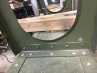
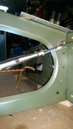
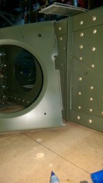
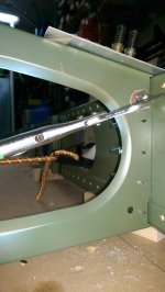
The tooling hole in the nose rib is useful, but the spars are located with grid lines on the table.
John Snap (n3uw) talked about building something he called torsion tables. I got carried away with the concept:
Also, about this time my son wrecked the car and I got a free source of labor.
Also - before the pandemic - wood was not a million dollars per foot.
I got him to weld up about a hundred of what airplane people call nut plates. These nut plates are made with 1/2 inch nuts.

Back on the subject of alignment, It was done using Pythagorean theorem - had to look up spelling.
You can see pencil lines on the table below. Two of the reference lines are parallel and 172 3/4 apart. (patrol).
The spars centers are 32 inches apart, but the other orthogonal lines are different from 32 inches to account for the capstrips.
On the front surface of the rear spar is a 1/16 capstrip. On the front of the Main spar is a total of 1/4 inches of capstrips.
So I made the other reference lines 32 3/16 apart.

This the main spar at the attach hole. I used a blue angle plate and a 1/4 lathe bit to extend the pencil line on table up to hole.

Below is a picture of the rear spar attach hole. The blue angle plate is on both pencil reference edges. The silver square is 1/16 thick. The 1/16 thickness accounts for the rear spar's 1/16 capstrips - which puts attach hole back off of pencil line by 1/16. The silver square also extends up the pencil line making both main and rear spar attach holes coplanar -(not coincident)
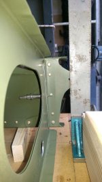
The rear spar is spaced up 1.34 inches with wood blocks.
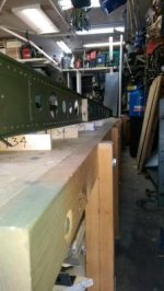
I often use lathe bits and 3/16 square keystock as measurement tools. The lathe bits are also very helpful when welding because they can take the heat.
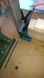
Below is the main spar. The wood squares hold the spar at right angles to table.
At this location the pencil line is extended up to the two 1/8 capstrips (1/4).
You can also see a 1/4 lathe bit. I need that lathe bit at the wing tip because there are no capstrips at the wingtip.
I set the lathe bit on the pencil line to make the 032 c-channel main spar offset from the pencil line by the correct amount.

In the picture below you can see scrap aluminum used to create a smooth transition of the spar and rib.
Because everything is done with a pencil line, there is only one degree of freedom left.
The spars are mounted parallel to each other and square to a level table using a rectangular grid drawn in pencil.
The spars are further more held apart with 2x4 lumber that can be made very accurately 32-0.032 long with square ends.
The spars are held together against 2x4 with bungee.
The rear spar height is set at 1.34 (patrol) off of table.
The main spar is on the table.
The center ribs from the day they were made had parallel edges the correct distance apart. (see first post about paranoia in making mdf form with parallel sides using a table saw with a jig slide.)
That leaves just the vertical height which is satisfied with that scrap aluminum.
I did use a string but only for the nose ribs. If you look closely, you can see a string going thru the center of
the nose rib tooling hole. I also used a piece of scrap aluminum to create a smooth transition at spar.
More blocks of wood are used to keep the nose ribs from being splayed.


 )