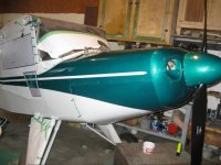
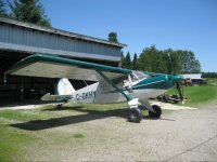
Whee. Thank you. Credit for the paint scheme goes to George Maddux's patrol. The emerald green & off white with a very fine metallic was the only colours that we all could agree on. George's airplane was a great example of green paint on an airplane.
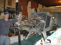
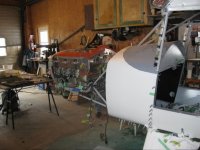
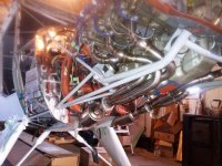
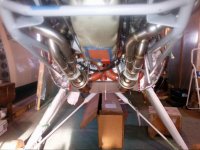
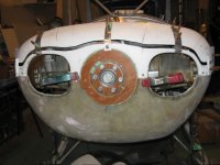
We lucked out on the engine mount. Barrows spec'd some heavy tubing for attaching the bed mount to the attach points. My welder partner was upset with the weight of a couple of them so I think our engine mounts will stand the test of time. Reworking the Cessna 337 rear mount certainly made the installation easy. An aircraft engine overhaul shop in Winnipeg gave us an empty cracked block that was perfect for the mock up work. The spinner flange almost got us with the nose bowl. I did the plywood disc support for the nosebowl & thought I was good on setback. Some tense moments fitting the cowl on after mounting the prop & the nosebowl cleared the back of the spinner by a 1/4". I wanted to seal around the prop hole on the engine side but did not manage it so the close fit is good. I read while researching pressure cowls to learn that a bad fit around the prop hole can lose up to 20% of the cooling air through the propeller hole. I think that if your exhaust goes right & left to leave a good clear run under the engine that you should have no issues with cooling. We added the aluminum half bulb or half tear drop radius on the firewall cooling exit. I read on one of the aircraft racer sites that this makes the exit air flow more laminar to assist the airflow. The sharp corners on the outlet creates turbulence that hinders air flow.
I don't know what the XP exhaust costs. We went with Aircraft Exhaust and that owner has taken back his original company Experimental Exhaust.
http://www.experimentalexhaust.com/
The owner Chris was great to work with and the work is first rate. My partner is a red seal welder and was impressed with the craftsmanship. They sent us the mock up parts and we routed the exhausts trying to keep all the runners about equal in length. We made an error on the cuff outlets as the heat duct crossed in front of the cowl cooling exit. We windowed the piece with the outlet with an offset the spun it 180 and TIG welded the piece back in. The exhaust was competitive & I can tell you what it was with a PM if that helps. The mock up parts are purchased & when the mock up is returned then the mock cost is fully credited to the completed exhaust. We had the skills to put an exhaust together but life is only so long and the airplane needs to get done. I also went out west as a part time hired gun for a three years so I paid for the exhaust in lieu of my absence. The header exhaust improves engine exhaust flow that could to give a percent or three improvement on hp. If it is 4 or 5hp then that is a plus.
We had planned to go to an electronic ignition that gives about 5-6% hp gains by the computer controlled variable timing plus the fuel savings. Between the exhaust and the electronic ignition that would put the engine around 225hp which is not bad. IO470 territory for power w/o the weight. Budget got in the way on the electronic ignition plus the delay on E-Mags 6 cylinder electronic ignition roll out. We had our name on the list but let it go.
I did a lot of modifications on the MC3A nose bowl & can give some detail if you are not there. I set the bowl in place and developed a template for the lower half. I then reshaped the bottom half of the purchased bowl with body putty and templating the left to right to stay symmetrical. Once I was happy with that then I waxed it the piece and then fiberglassed it to make a female mold, Added cushion foam for void stiffeners to the fiberglass mold and glassed those over to create a good stiff female. I then made a new fiberglass bottom with the mold. The top flange needed to go up about 1/2 an inch or so. I run a jig saw across the upper half and relocated the top with aluminum strips and clecoes. I glassed in the missing strip and it worked out well. I did not like the shape across the top so I sliced it in several places. The top shape was held with a plywood template backer then the cuts repaired to give me the new shape. I sanded it down on the inside and put a thin layer of glass on to restore its original thickness. Put the old fiberglass and body work skills to work. The white showing on the final assembly is the untouched areas. I enjoyed the creative process.
We weighed in on going with an 84 in. A lifetime of pump and fan laws got in the way. The PPonk tip speed calculator showed that at max rpm the 82 was just squeaking under the Mach1 tip speed for best efficiency. There was not enough knowledge in the team to know if going over Mach would put any bad harmonics into the engine. We are 2 hours between communities here that are in a line along the TransCanada hwy and the rest is thousands of square miles of empty bush or water with no walking home. We leaned to the max length on the known & proven side of the equation. I spoke to one AME had done many STC conversions and he upgraded his personal Cessna to the IO-360 power plant with an 86" prop. He said it was a scream but his neighbours hated it. It will be fun to see how yours works out.