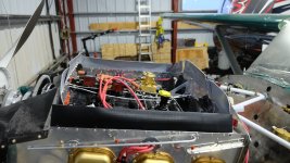
Another baffle query

DBeaulieu

Patrol Q/B Kit #79
Trying to make progress on engine baffles. Specifically, inlet baffle left side IO-360 with front prop governor. Figured out the right side inlet pretty much, but the engine casing extends further forward to the pulley and ring gear on the left side. The prop governor adds another consideration. So, I'm looking for ideas and input. Thanks for all thoughts and suggestions. Cheers! Dave

Baffle query edit with text.jpg
 
Last edited:
I have the same front governor installation. I made a fiberglass piece which the front cowling rubber seal will contact in a smooth arc to fully close off the inlet.
 

Attachments

  • photo18176.jpg
    photo18176.jpg
    94.5 KB · Views: 1
Here's what I did:
image.png - Click image for larger version  Name:	image.png Views:	0 Size:	5.06 MB ID:	95849​
There's a rubber baffle around the governor body to ensure a tight seal, which is held in place with a small blanking plate with nut plates installed on it.
In practice, you never need to remove the gasket without de-cowling first, I would use regular fasteners - nut plates are not necessary.
 
Last edited:
Battson Neat idea about the rubber material around the governor! I've been looking at other GA aircraft (older Cessna/Piper) around the airport and it seems that most don't even bother to baffle this area ... starting to wonder how necessary
 
Careful baffle sealing may or may not be necessary but it is a lot easier to do a complete a job on it now than it is to fix it up later. If you end up with a engine that runs hot, you will wish you had taken a little extra time now.
 
The O360 in my Patrol (fixed pitch prop) had no baffling around the front of the crankcase, so cooling air was entering at the front and diving down to exit below the engine before it had done any cooling work. The result was CHTs around 450 dF on climb out. Although this is below redline for Lycoming, it is well above what is best for engine longevity. The definition of max CHT is set by the FAA to be the highest temperature the factory could get without detonation or pre-ignition. So this has nothing to do with longevity. For Lycoming it is wise to set redline CHT at around 420 dF. For Continental it is about 400dF. (The metal and structure differs between the 2 engines.)

So now I have aluminum baffling very similar to the photos in this string. The rule of thumb is that the total of all leakage should be no more than roughly the size of an American quarter dollar coin. With the new baffling, my CHTs dropped by at least 30dF. I don't know why the original builder didn't baffle this area at all, cos it is huge air escaping. He did not have an engine monitor, so he would not have known the CHTs. I bought it with 70 hours, and he had only been pottering around the pattern, so I think the engine is still healthy. All the usual measures of engine health are really good - oil consumption, boroscope images, compression numbers, flight performance, etc.

What are my credentials for making these declarative statements? Two decades of very deep study (as a Mechanical Engineer) prompted by my Bonanza engine, which has had "problems". The Gurus on this subject are Mike Busch and the engine factory Gurus who present every year at Airventure Oshkosh. Oh, and never fly without an engine monitor! The JPI EDM 830 is an excellent choice, and factory support is very good.

Jim Herd
Minden, Nevada
 
I did a dual piece baffle around the governor as well, and beffle seal material similar to that. I did run my cable across the top of the engine, which works. But it complicates removing the baffles on that side of the engine. If I were to do it again, I would run it from the bottom
 
Thanks to all who have chimed in! Guess I'm convinced it will be worth the effort to accomplish now. Update when I make some progress...:rolleyes:
 
Cooling has always been a known issue with the -540 engines in Bearhawk aircraft, so this was a concern for me. It's possibly less important if you're installing a -360 engine, but better safe than sorry, especially if you find yourself in hotter climates or doing extended climbs.

Also, note that cooling drag is one of the larger sources of "reduceable" drag, if not entirely avoidable.

I was told a rule of thumb, if you can fit a pencil through a gap in the baffles, then the gap needs to be addressed. Solutions are either baffle metal, baffle rubber, or otherwise closed with RTV etc.
 
I have a 3" prop extension and was perplexed on how to seal the inlets to the boot cowl. Fortunately we have a Gold Lindy plans built winner in our EAA chapter whom I consulted with and copied what he did. His plane has round inlets and he did everything in aluminum, I used composites to achieve the same result. He has helped several members solve cooling issues so I knew I was getting good advise. He said if at all possible have your plenum area a rectangular shape with no dog legs as it is easier to get a good seal with the baffle material. So far I have been very happy with the result. My exit area is just the size of the tunnel, no additional cut out and no lip yet. My air inlets are sealed to the nose bowl with cut out bands of rubber from garden tractor inner tubes secured with safety wire. I have a very early version of the nose bowl from Avipro that I added composite flanges extending back from the inlets. It has not been very hot yet here so I may start running into cooling issues. Last week I departed Alamosa, CO at 85 deg and was surprised shortly into my climb needing to open the cowl flaps and decrease my climb rate. That was the first time I've used the cowl flaps since my first couple flights breaking in the engine. They are somewhat of a disappointment. My testing so far indicates they only decrease CHTs on average 9 deg F. Depending on how you installed your hinges for the cowling door, that is a source of cooling air loss. After I shut down I can see the hot air rising along the hinges. I will address that shortly with tape. Also at cruise one corner of my oil filler door lifts a little, I will start taping it down.

DSCF2167.jpg DSCF2161.jpg DSCF2166.jpg DSCF2263.jpg DSCF2931.jpg DSCF2934.jpg
 
Where are your cowl flaps located, if not the boot cowl tunnel?

Considering cowl flap installs in locations other than below the boot cowl tunnel, I am not yet aware of any which have worked as effectively (or more effectively) as cowl flaps matched up with the boot cowl tunnel.

The other thing you can add is a rounded tunnel exit lip, where the firewall meets the tunnel, if you haven't already installed one.
 
Back
Top