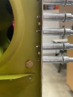
Aux tank covers - screw placement?

Dpearson

4-Place QB (A Model)
Hi all,

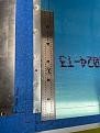
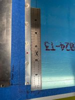
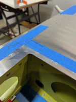
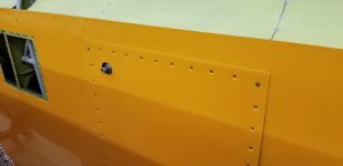
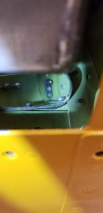
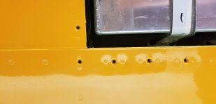
I'm puzzled about locating the screws/nut plates for the aux tank covers on my A-model wings. The build instructions say to position them "...so they fall midway between the existing skin rivets (to give room for nut plates, etc.)," It seems if I do this I won't have screws at the corners of the covers - the first screw on each edge would be about 1-1/8" in from the edge of the cover:
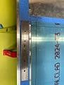
thumb_13842.jpg​
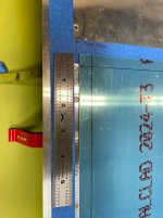
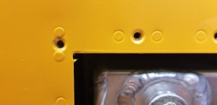
And, the rearmost "between the rivets" location on the long edges of the cover is directly in line with the rear spar, so it doesn't seem possible to put a screw there - which would place the rearmost screw on each edge roughly 2-1/2" forward of the aft edge of the cover​​ screw locations.
thumb_13846.jpg

The "replace all the rivets with screws and nut plates" approach seems like it would end up matching the design of the main tank cover's interface to the wing, but also seems like a lot of work for questionable benefit.

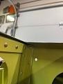
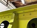
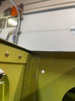
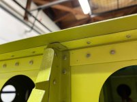
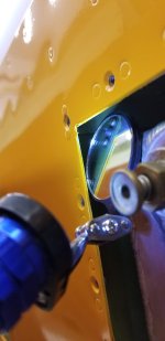
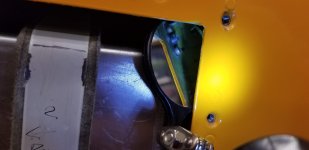
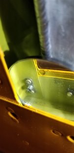
Here's a couple more pictures of the rear edge of the opening:
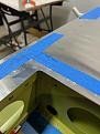
thumb_13846.jpgthumb_13847.jpgthumb_13848.jpg​​​

Any input would be welcome!
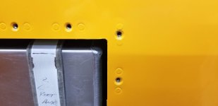
 

Attachments

  • photo13842.jpg
    photo13842.jpg
    620.9 KB · Views: 0
  • photo13843.jpg
    photo13843.jpg
    783.7 KB · Views: 0
  • photo13846.jpg
    photo13846.jpg
    464.1 KB · Views: 0
  • photo13847.jpg
    photo13847.jpg
    358.4 KB · Views: 0
  • photo13848.jpg
    photo13848.jpg
    430.8 KB · Views: 0
The first wing I located screws/nutplates between the existing rivets. I did drill out the corner rivets and due to space limitations used miniture one leg nutplates. I decided for the 2nd wing, drilling out the existing rivets and replacing with nutplates was the better method and still feel that way. I don't know why you think that would be more work. Existing rivets can be drilled out quickly because you aren't worried about maintaining original hole diameter. You save the layout time for new holes.
 
David, I've never done it so I don't have much technical help, but once you have a good plan let me know and I'll update the entry at bearhawk.tips.
 
I have my wings in a cradle so it's hard to take pictures of the underside. I'll try to look through my archives and see what I did. My kitlog has some entries, but not for what you are asking for specifically.

http://www.mykitlog.com/users/displ...a&project=527&category=3973&log=241170&row=59

I agree with Rod. If you have to drill out some existing rivets it's no big deal. It might actually help you in spacing out nutplates! I think I did single-leg nutplates in the corners. I'll try to find out for sure if I can get some help with holding the wing. Tanks are in and ready to go, but I should be able to have a look.

20230306_201057.jpg
 
I was able to get the wing moved a bit in the cradle enough to get the tank cover off. I took pics of the outside of each corner and then took pics of the inside of the same corner using a mirror. You can see the rivet outlines in the paint. The pics are labeled Front right A for the outside, Front right B for the same area but with a mirror, etc. Front is toward the LE, right is toward the wingtip. I used the tiny two-lug nutplates for all corners except for the front right where I used a tiny one-leg nutplate. Hope this helps...

Back left A.jpgBack left B.jpgBack right A.jpgBack right B.jpgFront right A.jpgFront right B.jpgFront left A.jpgFront left B.jpg
 
Wow thanks for taking the time to open the bay and take all the photos. I made good progress this evening, all rivets drilled out (except 2 on each rib which I have temporarily left in place to ensure no rib movement vs the skin), and cover match drilled. I appreciate the help!
 
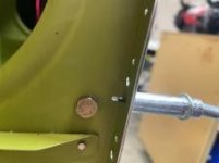
Epilogue: It took way longer than I expected but I got one cover done. Drilling out all the existing rivets worked great. The only significant challenge was that each rivet location, when updrilled to #27, has the remnants of the dimple that accommodated the AN426 rivet head which forms residual “volcano” on the inner surface:
dataurl516733.jpg

Left untreated, these kept the nut plates from sitting flat on the surface of the flange:
dataurl516737.jpg
I used a back spotfacer (turned by hand) to bring these protrusions down to an acceptable height so the nut plates would sit flat. ​
jaredyates I did a brief writeup (Attached here) for consideration for the bearhawk.tips site. I hope it's helpful!
 

Attachments

Yes, I considered k1100-06 dimpled nut plates. They would have been time savers but at $3.35/ea (Aircraft Spruce) * 120 locations I had trouble justifying the increased cost. The spotfacer tool cost a lot less (< $50 I believe) and I got a new tool out of the deal!
 
Back
Top