Franks LSA

Frank

Well-known member
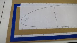
Finally able to start my project! First step is to turn mylar drawing #4 into a template.

I didn’t like the idea of gluing down the mylar and cutting it out: I want to preserve it instead.

And I didn’t like the idea of cutting to the inside of the line: once the line disappears I don’t know where I am.

Took the mylar to a reprographics shop and had it scanned.

At home, I took the scan into Photoshop and turned the single outside line into a double line, easy to do.

The inside of the two new lines represents the inside of the original line.

Now I have a line I can cut just to the edge of, leaving that reference line visible.

Printing full size was problematic so I ended by printing at home and splicing the pages.

A slight pain but it gave me the advantage of aligning to the mylar drawing more easily.

When everything was aligned I taped and spliced onto half-inch MDF.

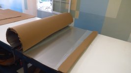
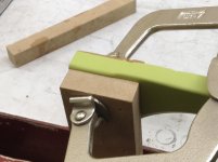
I cut the paper drawing free of the board and was ready to apply spray adhesive.

In my first attempt I sprayed adhesive onto the paper and struggled to lay it down properly.

In the second attempt I sprayed the adhesive onto the board instead, masking off non-spray areas.

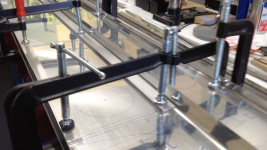
Also made a jig which would suspend the drawing above the board, allowing for easier application.

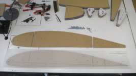
The mylar on top of the glued drawing matches well and confirms alignment.

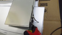
Then used the jig saw to rough cut the piece close to the lines.

Replaced the 80 grit with 120 grit on the disc sander, but the soft MDF is removed very quickly at 1750 rpm.

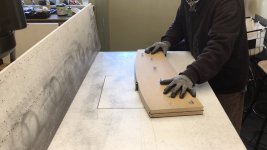
Used the disc sander in this way to get close to the line.

But it was by turning the motor OFF and using the disc sander manually was able to refine the edge.

Turning the disc with my thumb and sliding the piece on the work table made minute adjustments easy.

A bright light helps a lot as well as supporting the ends of the piece.

Repeatedly laying it on top of the mylar drawing and taking it back to the disc sander did the trick.

Now I have a template which matches the mylar drawing just to the inside of the line.

Yay!
 

Attachments

  • photo7654.jpg
    photo7654.jpg
    1.5 MB · Views: 1
  • photo7655.jpg
    photo7655.jpg
    1.6 MB · Views: 1
  • photo7656.jpg
    photo7656.jpg
    1.7 MB · Views: 1
  • photo7657.jpg
    photo7657.jpg
    1.7 MB · Views: 1
  • photo7658.jpg
    photo7658.jpg
    1.6 MB · Views: 1
  • photo7660.jpg
    photo7660.jpg
    1.6 MB · Views: 1
  • photo7661.jpg
    photo7661.jpg
    1.5 MB · Views: 1
  • photo7662.jpg
    photo7662.jpg
    1.7 MB · Views: 1
  • photo7663.jpg
    photo7663.jpg
    1.6 MB · Views: 1
  • photo7664.jpg
    photo7664.jpg
    1.6 MB · Views: 1
  • photo7665.jpg
    photo7665.jpg
    1.8 MB · Views: 1
  • photo7666.jpg
    photo7666.jpg
    1.7 MB · Views: 1
  • photo7667.jpg
    photo7667.jpg
    1.5 MB · Views: 1
To prepare for the first aluminum order, working up a parts list and a materials list and learning a lot in the process.

Making a parts list forces me to examine the drawings very closely; there are certain things I don’t understand yet...

The materials list can’t be determined until I get on the phone and work out the best deal and delivery.

Planning for extra material to allow for 2nd and 3rd attempts. Probably need an extra sheet of .032 for spars.

Looking too far ahead and I’m overwhelmed. So I stick to the immediate steps I need to make.

Glad I had the plans scanned to files: handy to use the computer for studying, copy/pasting, even measuring.

View attachment parts_materials_1.pdf
 
Hi Frank, Have you looked at Marks Rib and Spar blank kit? It would be a big time saver if it is worth it to you.
 
Hi Dave, yeah I should really take a look. Actually looking forward to making the ribs.
It would be nice though, if Mark would let me send him some representative ribs after I make them.
And then he could bend the spar blank to match my ribs - the 8 foot brake being something of an obstacle. :)
 
See the video in my post John's LSA build. Just posted today. I built a brake, and had good results.
 
Update: improved the 4 x 16 worktable a bit but certainly not a perfect reference plane, but OK for making ribs.

The plan is to create a spar assembly jig on the table using a laser and make that perfect.

Then disassemble the table and make room for wing assembly jig when the time is right.

Currently I have the master and working templates done, the form blocks and backup block, and the router cutting templates.

I picture the my master template as a duplicate of what Bob used to make the Mylar “full size wing rib form block layout”.

My intention is to use two full length form blocks for all the rib sections, left and right, with a 10° bevel and indents for flutes.

I just put in an order for .020 and .025 2024-T3, enough to make the ribs (except for no. 1) plus extra.

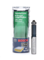
Will work on the form blocks while waiting for the shipment. Looking for a router bit for the bevel and indents.

Use a HF trim router or other small rotary tool for all the bend radii, then harden the edges with varnish/epoxy.

Always reference back to the master and working templates, maintain the dimensions and contour.

My plan is to flange all of the ribs first, before cutting any lightening holes either in MDF or aluminum.

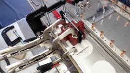
Made a table saw sled for trimming templates and rib blanks to length.

Will use the table router to trim the edges of the aluminum blanks, in multiples.

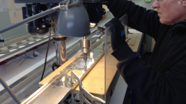
But I want to use the drill press and fly cutter to cut lightening holes at 300 rpm.

Testing this method works so far: cuts nice holes and circles, dust is manageable.

Can add 40° bevel to the male dies using sandpaper and the drill press as a vertical lathe.

I don’t see an advantage to having the holes cut in the MDF or blanks before flanging.

Will have to cut 400+ lightening holes individually, though.

Form the lightening hole flanges with the dies and arbor press.

Also on the near horizon is to contact EAA technical counselor(s) and arrange for meetings.

And pretty soon start an EAA builder log.

So far things are coming together nicely and it is quite enjoyable! :D

fullsizeoutput_f6b.jpegIMG_0043.JPGIMG_0038.JPGfullsizeoutput_f4b.jpegfullsizeoutput_f3b.jpegfullsizeoutput_f4d.jpegfullsizeoutput_f41.jpeg
 
Little problems which have to be figured out. Like how to safely uncoil 4-4x12 sheets of .020. Bar clamp the roll to the workbench in such a way that when the packaging tape is cut, only the free end will come out. Thwack! The rest stays clamped down. Thereafter, using spring clamps to hold the roll together, ease it out gradually. The potential energy diminishes as it unrolls and by the end, it's easy to handle. Nothing brilliant but made me happy.

My layout of the rib sections is tighter than what I had calculated, so there will be even more excess than planned. But I didn't order all the .020 at once so I'll be able to use it. Also ordered some .025.

The Harbor Freight snips work great, easy to cut this thin material.

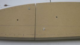
Realized now that all the cutting template holes need drill guides, not just the master and working templates. I'm using 5/16 x 3/4 tension pins which fit snugly in the MDF. The inside diameter is just right for the 3/16 carriage bolts.
 

Attachments

  • photo8013.jpg
    photo8013.jpg
    1.3 MB · Views: 1
  • photo8016.jpg
    photo8016.jpg
    1.4 MB · Views: 1
  • photo8015.jpg
    photo8015.jpg
    1.4 MB · Views: 1
  • photo8014.jpg
    photo8014.jpg
    1.4 MB · Views: 1
  • photo8017.jpg
    photo8017.jpg
    1.5 MB · Views: 1
Last edited:
"I don’t see an advantage to having the holes cut in the MDF or blanks before flanging."

Depending on how you approach cutting the lightening holes. I put the rib blanks in between the MDF routing templates and drilled "starting holes" in each lightening hole. Then I routed both the outside of the blank and the lightening holes instead of using a fly cutter.
 
That does seem to be a popular method. But here's my thought process, such as it is:

The LSA book of instructions is clear on the sequence: "After forming the rib, it's time to cut the lightening holes and flange them." Also on the forum someone had this confirmed by Bob (now I can't find that comment).

My intuition is probably worthless since this is all new to me but I suspect having lightening holes as close as 1" to the form block while flanging the rib is an invitation to unnecessary deformations, not that I've seen any complaints about this.

I like the router for trimming the outer edges of the blanks and I have the shop vac set up to catch 100% of the debris from these cuts. The rough-cut blanks will all be within about 1/2 radius of the cutter for the outer edges.

But how to efficiently vacuum while cutting inside the holes with the router which is using the full diameter of the cutter? There's probably a way. But I think controlling debris will be easier with the 300 rpm drill press.

Router versus fly-cutter each have their own safety issues. On the drill press I can clamp the work down and use the column as a brace. And I have a plastic shield on a goose-neck placed in front of the work. The router means I have to rotate the work on the table and concentrate on how the circle is fed into the cutter.

The router is loud, the fly-cutter is not. Nobody would hear me scream over the router noise.

As for speed of fabrication, Bob would have us doing it all by hand! :D

Edit: Though come to think of it, if you flanged the all lightening holes by hand with the bob-stick, as instructed, you'd have a lot of them done in the time it takes just to get set up with templates and dies and so forth...
 
Last edited:
Certainly lots of ways to do it and some of them will be best defined by our surroundings.

The router does make a mountain of small chips that end up everywhere and it is noisy(wear hearing protection). Best done outside where you wouldn't mind seeing aluminum "snow" for a few months after you are done.

As far as flanging, I used the "rubber press" method. It simply required using the router to chamfer the lightening holes in the form block and a hydraulic shop press(with some random metal chunks for platens and a stack of random rubber for the working). Saves time over making multiple flanging dies but again, more than one way to do it.

Not sure if you have seen it, but when I finished mine I posted links to a pretty extensive build log(IIRC, it is in my "First Flight" post from about three years ago,)https://bearhawkforums.com/forum/bearhawk-lsa-plans-build/28647-first-flight-today). Again, it shows how I did things, not necessarily the best way but one way that led to a flying airplane.
 
Thanks BTAZ, I have your wings .pdf and have studied it! (I'll download the other two now make sure I don't lose them.) Pretty sure I'll cut lightening holes with the fly cutter. But I should carefully weigh the option, as you suggest, of the rubber press method! :D
 
After making a set of ribs using the wood die method, I believe that the rubber press method superior. The apparent quality after flanging was superior, meaning way less deforming took place with the rubber press.
 
Drawing outlines on the aluminum sheets and rough cutting with snips. The .020 cuts easily and the parts can be laid out very close. The .025 cuts less easily and needs a little more space between parts.

In retrospect, if you’re going to layout everything on the computer to estimate material needs, then you might start by laying out the skins first. Start with the biggest parts and work down to the smallest.

Also in retrospect, while laying out the rib blanks on the aluminum with the sharpie, I could have made punches for the jig pin holes at that time. On the other hand, punching after the rough cut allowed me to punch two blanks at one time.

I used a hammer and awl. A precise 3/16 center punch might have been better.

All the holes in the cutting templates have 5/16 OD steel tension pins with ID of 3/16. On the drill press, the guides not only protect the hole but also help to center the drill by pulling the piece into alignment.

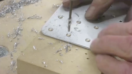
The initial jig pin holes drilled first. A 3/16 round file is helpful. Then, many blanks can be sandwiched together and the other holes drilled. While the sandwich is pinned, individual holes can be reamed out. This results in a blank which fits easily over the pins. In reality, these are 3/16 x 2 1/2 in. carriage bolts, flat washers and wing nuts.

Sandwiching five blanks at a time (four at a time for .025) ran these through the router with flush cutting bit. The cutter has two straight blades which throw the tiny chips horizontally. A vacuum attachment is set as close as possible and catches 90% or more of the chips.

The nose ribs will be put back into the template sandwich and the 3/16 relief holes drilled and filed. Likewise, the relief holes of the aileron and pocket rib notched flanges to be drilled. Then I plan to cut the notches first with the jig saw and finish with the file. The holes on the LSA measure 3/16.

So that’s where I’m at now. Next step will be get the form blocks freaky for flange-making.

https://www.dropbox.com/s/86ptmvzd0trg53i/nose ribs4.mp4?dl=0

Also, I have been advisedto take off the gloves while operating stationary power tools that have moving or spinning parts. I intend to learn this lesson from advice and not from experience!

https://www.osha.gov/Publications/osha3151.pdf
https://www.osha.gov/Publications/osha3170.pdf
 

Attachments

  • photo8244.jpg
    photo8244.jpg
    1.6 MB · Views: 0
  • photo8245.jpg
    photo8245.jpg
    1.6 MB · Views: 0
  • photo8246.jpg
    photo8246.jpg
    1.5 MB · Views: 0
  • photo8247.jpg
    photo8247.jpg
    1.5 MB · Views: 0
  • photo8248.jpg
    photo8248.jpg
    1.5 MB · Views: 0
  • photo8249.jpg
    photo8249.jpg
    1.7 MB · Views: 0
  • photo8250.jpg
    photo8250.jpg
    1.5 MB · Views: 0
  • photo8251.jpg
    photo8251.jpg
    1.5 MB · Views: 0
  • photo8252.jpg
    photo8252.jpg
    1.4 MB · Views: 0
  • photo8253.jpg
    photo8253.jpg
    1.4 MB · Views: 0
  • photo8254.jpg
    photo8254.jpg
    1.5 MB · Views: 0
  • photo8255.jpg
    photo8255.jpg
    1.6 MB · Views: 0
  • photo8256.png
    photo8256.png
    200.9 KB · Views: 0
Last edited:
Also in retrospect, and this is likely aesthetic only, the center rib template and blanks should probably have an angle added to front and back top flanges. An angle is indicated on the nose rib in the plans but I didn't extrapolate the corresponding angle on the center rib flange. Likewise the center/back rib. This is because, although it's a "90 degree flange", you're folding over an additional angle, making it a compound angle and the straight line becomes a bent line when you fold it over. Which means, the folded edge of my center-rib-flanges will angle away from the bend. That edge of the flange will not be parallel to the spar. Easy to check out with a scrap of paper. And better do that before cutting the piece.

Not to worry, but makes me wonder: where else might I fail to extrapolate, and where might that happen in a more significant way? :D
 

Attachments

  • IMG_0025.JPG
    IMG_0025.JPG
    1.4 MB · Views: 0
  • IMG_0026.JPG
    IMG_0026.JPG
    1.5 MB · Views: 0
Last edited:
Finally I have a system rigged up to produce rib flanges.

The two form blocks (which are copies of the working template) were run through the router using a flush cutting bit, an angled fence, and and inclined table. This resulted in a 10 degree bevel, one for “left” flanges and one for “right” flanges.

Using a 1/16 radius roundover bit in a small trim router, went around the working edges of the form blocks, even though the LSA book specifies 1/32.

Studied and thought a bit, then marked rivet locations. Then indicated the flute locations, which are slight grooves and serve as initial guides.

Gave the working edges and surfaces a couple of coats of a wood hardener. Hopefully this will help the form blocks and backup block hold up to the abuse.

Made a practice set up (form block and backup block) which replicates the tightest curve on the nose rib and worked on bending technique.

Making homemade fluting pliers was more a rite of passage than anything else. They are so-so, and I see how I could do better a second time. But it’s pretty hard on the drill press. Fluting pliers I bought from Airports Inc. work much better.

B-Spot on youtube inspired me to make a table mounted fluting vise along with the Vans-style rib straightener. The fluting vise gives a nice moderate 3/16 flute. And the Vans rib straightener really works, though I may need to refine the angle. It also serves as a flute reducer.

The only difficult areas are at the first three or four flutes over the front of the nose rib. These seem to require a bit of the store-bought fluting pliers to get a little deeper. And smooth-jawed pliers to go in and fine tune the flange. The trailing edge of the back rib is too tight for the rib straightener but it’s workable with the pliers.

So that’s the plan going forward: bend the flange over in the form block and start the flutes using a 3/16 rod and hammer. I can do a nose rib and center rib at the same time. The back rib is done separately. The pieces come out of the jig with close to a 90 degree flange. The flange is refined with the fluting vise, rib straightener and pliers.

The goal is to create rib flanges where the inter-flute surfaces match the line of the airfoil, as opposed to bowed surfaces between the flutes. Maximize contact between the flange and the skin, and not rely on the skin and rivets to pull the flange into shape.

We’ll see how it goes! :D
 

Attachments

  • photo8379.jpg
    photo8379.jpg
    1.4 MB · Views: 0
  • photo8381.jpg
    photo8381.jpg
    1.7 MB · Views: 0
  • photo8382.jpg
    photo8382.jpg
    1.4 MB · Views: 0
  • photo8384.jpg
    photo8384.jpg
    1.3 MB · Views: 0
  • photo8386.jpg
    photo8386.jpg
    1.3 MB · Views: 0
  • photo8388.jpg
    photo8388.jpg
    1.5 MB · Views: 0
  • photo8389.jpg
    photo8389.jpg
    1.5 MB · Views: 0
  • photo8390.jpg
    photo8390.jpg
    1.5 MB · Views: 0
  • photo8391.jpg
    photo8391.jpg
    1.5 MB · Views: 0
  • photo8392.jpg
    photo8392.jpg
    1.5 MB · Views: 0
  • photo8393.jpg
    photo8393.jpg
    1.5 MB · Views: 0
  • photo8394.jpg
    photo8394.jpg
    1.5 MB · Views: 0
  • photo8395.jpg
    photo8395.jpg
    1.5 MB · Views: 0
  • photo8396.jpg
    photo8396.jpg
    1.5 MB · Views: 0
  • photo8397.jpg
    photo8397.jpg
    1.5 MB · Views: 0
  • photo8398.jpg
    photo8398.jpg
    1.7 MB · Views: 0
  • photo8399.jpg
    photo8399.jpg
    1.3 MB · Views: 0
  • photo8400.jpg
    photo8400.jpg
    1.4 MB · Views: 0
  • photo8401.jpg
    photo8401.jpg
    1.7 MB · Views: 0
  • photo8402.jpg
    photo8402.jpg
    1.7 MB · Views: 0
Last edited:
Click image for larger version  Name:	fullsizeoutput_102d.jpeg Views:	0 Size:	1.64 MB ID:	61368Click image for larger version  Name:	fullsizeoutput_102d.jpeg Views:	0 Size:	1.64 MB ID:	61368
About a quarter of the way making basic rib flanges. With a ten degree bevel they come off the form block with close to a ninety degree flange.

Seems to be working out okay, though the backup block is taking a beating. I'll have to duplicate it soon. And when the time is right, I'll use the two backup blocks as the hole flanging jigs. Testing the arbor press and die seems pretty straightforward. Got the bob-stick ready.

Thinking about a little contact cement inside the die jig sandwich to minimize the aluminum sliding/stretching (along with as much clampage as I can get).
 
Last edited:
As I study and work to understand, it helps me to separate out parts which in the plans are drawn overlapped. I had the plans scanned into pdf files, so it's now easy to go in and make tracings. Not for accuracy or dimensions, just to see more or less what's what.

This, like my materials and parts lists, is a work in progress. wing spars 01.png
 
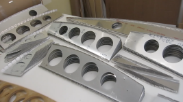
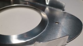
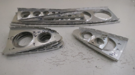
Completed all basic rib flanges except for the two .032 center root ribs. They came off the 10 degree beveled form blocks with a nearly 90 degree flange. Did a "basic" job of straightening and flattening. Adding lightening holes with flanges will add new distortions, so at this point I didn't strive for perfection.

The form blocks and back up blocks are showing signs of wear, though still useable. I doused each with Minwax wood hardener a couple of times through the process. Not entirely sure it does any good.

One small alteration to the method was added, and that was to flute the top of the nose rib blank before bending. It is just that area where the curvature of the airfoil is greatest which tended to produce annoying wrinkles. But starting the flutes before bending made this go smoother. This was suggested to me by a Zenith builder.

The short video shows trying to get the most out of the table-top fluter and rib straightener, applying pressure at different points, really digging it in.

The aileron and pocket ribs were bent over straight (non-beveled) form blocks. Easy enough to straighten the flanges with smooth jawed pliers. I was struggling with the top/bottom dimension of the pocket ribs, but decided to leave the bottom tab flat. Will bend that upon assembly to get the best fit.

All the pieces will need to be trimmed to length upon assembly. All the cutting templates and form blocks are intact and still usable if necessary.

But for now, it's on to the lightening holes! :D

https://www.youtube.com/watch?v=s7LzdksBPOw
 

Attachments

  • photo8664.jpg
    photo8664.jpg
    1.8 MB · Views: 0
  • photo8665.jpg
    photo8665.jpg
    1.3 MB · Views: 0
  • photo8666.jpg
    photo8666.jpg
    1.6 MB · Views: 0
  • photo8667.jpg
    photo8667.jpg
    1.7 MB · Views: 0
  • photo8670.jpg
    photo8670.jpg
    1.6 MB · Views: 0
  • photo8671.jpg
    photo8671.jpg
    1.6 MB · Views: 0
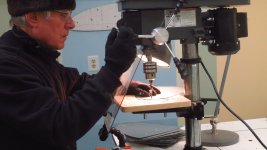
Those debating which method to use for cutting and forming the lightening holes may find this useful. Might make you more convinced than ever that the router method is the way to go. But I'm glad to be using the fly-cutter and drill press. Next step will of course be to form the lightening hole flanges using the dies and arbor press.

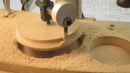
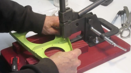
Using the two backup boards from the rib flanging step, the oversize holes were cut, creating a rib-sandwich jig. First, they serve to hold the ribs in place for cutting. Secondly, the holes are the bending edges over which the dies forms the flanges.

Cutting from both sides of the material gives me the cleanest edges. This applies to both MDF and aluminum. Cutting all the way through from one direction is problematic. So for the most part, I start the cut from one side, flip the piece over, then finish the cut from the other side. Alignment is not a problem with the guide hole.

Since I am leaving the plastic film on the aluminum as long as possible, this also causes problems trying to cut through from one side. The plastic can interfere with the cut and also trap chips underneath around the hole.

Fortunately, the smaller holes presented much fewer problems and I was able to cut through cleanly from one side.

The cutter will grab and bind, both in the MDF and the aluminum. But when the cutter stops, the motor just slips on the pulley. In other words, the full torque of the motor is not applied to the work when the cutter binds. You just back off and the cutter resumes spinning. And an extreme amount of clamping is not required.

The drill press and hole cutter method is not loud and the dust and shavings are easily contained by the safety shield. Other measures include not wearing gloves, and plugging in to a switched outlet.

The video shows it in detail:
[url]https://www.youtube.com/watch?v=bVcHegOH8yE[/URL]
 

Attachments

  • photo8790.jpg
    photo8790.jpg
    1.4 MB · Views: 0
  • photo8791.jpg
    photo8791.jpg
    1.5 MB · Views: 0
  • photo8792.jpg
    photo8792.jpg
    1.4 MB · Views: 0
  • photo8793.jpg
    photo8793.jpg
    1.4 MB · Views: 0
  • photo8794.jpg
    photo8794.jpg
    1.6 MB · Views: 0
  • photo8795.jpg
    photo8795.jpg
    1.5 MB · Views: 0
  • photo8796.jpg
    photo8796.jpg
    1.4 MB · Views: 0
  • photo8797.jpg
    photo8797.jpg
    1.4 MB · Views: 0
  • photo8798.jpg
    photo8798.jpg
    1.5 MB · Views: 0
  • photo8800.png
    photo8800.png
    1.4 MB · Views: 0
  • photo8801.png
    photo8801.png
    1.7 MB · Views: 0
  • photo8802.png
    photo8802.png
    1.3 MB · Views: 0
Last edited:
Naturally, now that I'm almost done flanging the lightening holes, I start to second-guess myself. For the outer flanges of the ribs, I radiuses the edges to 1/16 inch. (The Bearhawk LSA Book says to radius these edges to 1/32.)

But I didn't radius the edges of the lightening hole forms. My test seemed to indicate it was not necessary. And indeed all of the lightening hole flanges have a visible bend radius even though bent over a sharp edge.

Now I bent a piece of .020 over a sharp edge to 90 degrees and it has a radius of about 1/32 as near as I can measure. Visually it is about half the bend radius of my 90 degree rib flanges.

Table 4-6 in AC 43.13-1B gives recommended bend radii for 90 degree bends. For .020 that is just a little less than 1/32 (and see the table footnote). It doesn't mention 30 degree bends.

I'm not trying to achieve the minimum radius. But I think I am ok with the bend radius of my lightening hole flanges.
 

Attachments

  • photo8897.png
    photo8897.png
    76.6 KB · Views: 0
  • photo8898.jpg
    photo8898.jpg
    127.8 KB · Views: 0
  • photo8899.jpg
    photo8899.jpg
    362.8 KB · Views: 0
  • photo8900.jpg
    photo8900.jpg
    977.7 KB · Views: 0
  • photo8901.jpg
    photo8901.jpg
    1 MB · Views: 0
  • photo8902.jpg
    photo8902.jpg
    1.1 MB · Views: 0
  • photo8904.jpg
    photo8904.jpg
    1.5 MB · Views: 0
Last edited:
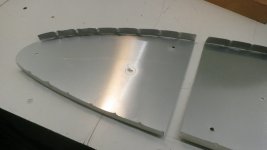
The ribs were sandwiched between the two backup blocks/lightening hole jigs and the flanges were pressed using the MDF dies and the arbor press. It was important to press lightly at first and rotate the die in order to get an even angle on the flange. Also important to not continue to press or press too hard because cracks may develop.

There were some rejected pieces because of cracks, and even though I made extras to begin with, I am still short one back rib and one aileron rib. I won't remake these pieces yet because I may discover more rejects as I move forward. The plastic protective film is still on the aluminum, not to be removed until it's time to de-burr.

The ribs had been fluted and straightened but the lightening hole flange pressing created a new distortion in the ribs. This was removed using the bob-stick by stretching and lifting the flanges in the proper locations. I used a sweeping motion while pulling on the bob-stick in order to keep the flanges smooth.

Also some adjustments to the ninety degree outer flanges and flutes were made. Overall, the ribs are now in pretty good shape with regard to flatness and straightness. I suspect I will be tweaking them again before and after adding the stiffener angles and upon assembly.

The youtube video shows the entire process.

[url]https://www.youtube.com/watch?v=rLwtF_EmOeY[/URL]
 

Attachments

  • photo9080.png
    photo9080.png
    1.4 MB · Views: 0
  • photo9081.jpg
    photo9081.jpg
    1.1 MB · Views: 0
  • photo9082.jpg
    photo9082.jpg
    977.7 KB · Views: 0
  • photo9083.jpg
    photo9083.jpg
    1.7 MB · Views: 0
  • photo9084.jpg
    photo9084.jpg
    1.5 MB · Views: 0
  • photo9085.jpg
    photo9085.jpg
    1.5 MB · Views: 0
  • photo9086.jpg
    photo9086.jpg
    1.4 MB · Views: 0
  • photo9087.jpg
    photo9087.jpg
    1.7 MB · Views: 0
  • photo9088.png
    photo9088.png
    630.9 KB · Views: 0
  • photo9089.png
    photo9089.png
    659.7 KB · Views: 0
  • photo9090.png
    photo9090.png
    790.5 KB · Views: 0
  • photo9091.png
    photo9091.png
    859.2 KB · Views: 0
  • photo9092.png
    photo9092.png
    814.2 KB · Views: 0
  • photo9093.png
    photo9093.png
    993.9 KB · Views: 0
  • photo9094.png
    photo9094.png
    955.9 KB · Views: 0
  • photo9095.png
    photo9095.png
    1.2 MB · Views: 0
This is my pile of rejects so far. Either there are cracks or the flanges are too eccentric or I have mangled the piece beyond repair.
 

Attachments

  • photo9096.jpg
    photo9096.jpg
    1.8 MB · Views: 0
My biggest goof so far: gap between nose rib lightening hole flanges is 3/8 instead of 1/2.
I sent Bob a picture with my proposed solution and he replied “3/8 as you show will work good”.
The centers of the holes are correct so the mistake occurred when scaling up from the drawing.
​​​​​​​Will adjust rivet locations for better spacing.
It's a warning and foreshadowing: must look forward to see the consequences of all measurements.
I fear my lack of comprehensive understanding of the plans will bite me harder next time!
 

Attachments

  • photo9118.jpg
    photo9118.jpg
    1.4 MB · Views: 0
Last edited:
Obviously there are other ways to go about it but these are the steps I took to make the rib stiffeners:

1. Cut the 1 inch blanks on the table saw using a sled and stacked rough cut pieces of aluminum.

2. Trim the blanks on paper cutter. There are five separate lengths and as many as 36 each.

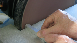
3. Make five drill guides from 1/2 inch aluminum bar stock from hardware store. Cut the bar with jig saw and refine the ends with disk sander. Make a jig to hold the piece and drill the holes. Add nails as jig pins and insurance. Add a slight chamfer to each hole to aid the drill guide.

4. Stack six or eight blanks with the drill guide in the jig and clamp together. The jig rides freely on the drill press table and the drill guide does the work of alignment. Add the nails again as jig pins as insurance.

5. Use the disk sander to cut the angles into the stack of blanks.

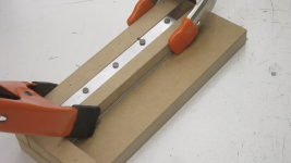
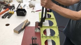
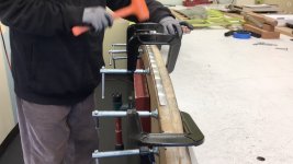
6. Use a simple bender to form the angles. Made from MDF and 1/8 masonite. A 10 degree angle is cut into the fence/shoe/ clamp. The 1/8 material brings the bend to the center of rotation. A piece of aluminum under the shoe serves as a 1/2 inch stop. Three nuts and washers are torqued down to clamp it together.

7. Using the drill guide and cleco-clamps, measuring from the spar-ends of the ribs, drill the holes in the ribs. “Left” and “right” ribs use the same drill guide, just rotated 180 degrees.

8. Randomly cleco ribs and stiffeners together to check the fit.

Photos not in sequence.

See the Youtube video for steps in detail:
[url]https://youtu.be/QVNxnR8ypY8[/URL]
 

Attachments

  • photo9568.png
    photo9568.png
    1 MB · Views: 0
  • photo9569.png
    photo9569.png
    1 MB · Views: 0
  • photo9570.png
    photo9570.png
    1.3 MB · Views: 0
  • photo9571.png
    photo9571.png
    1.3 MB · Views: 0
  • photo9572.png
    photo9572.png
    1.5 MB · Views: 0
  • photo9573.png
    photo9573.png
    1.5 MB · Views: 0
  • photo9574.png
    photo9574.png
    1.8 MB · Views: 0
  • photo9575.png
    photo9575.png
    1.9 MB · Views: 0
  • photo9576.png
    photo9576.png
    1.9 MB · Views: 0
  • photo9577.png
    photo9577.png
    2 MB · Views: 0
  • photo9579.png
    photo9579.png
    1 MB · Views: 0
  • photo9580.png
    photo9580.png
    1 MB · Views: 0
  • photo9581.png
    photo9581.png
    1.4 MB · Views: 0
  • photo9582.png
    photo9582.png
    1.4 MB · Views: 0
  • photo9583.png
    photo9583.png
    1.5 MB · Views: 0
  • photo9584.png
    photo9584.png
    1.5 MB · Views: 0
  • photo9585.png
    photo9585.png
    1.6 MB · Views: 0
  • photo9586.png
    photo9586.png
    2.1 MB · Views: 0
  • photo9587.png
    photo9587.png
    2.1 MB · Views: 0
Hey Frank i really liked your idea of the drill guides for making the rib stiffener angles. I have not started on my wings yet but i am gathering all the materials for them. I wanted to ask what model blade are you using in your table saw to cut the aluminum bar?
 
Last edited:
I think the 10 inch circular saw is a Diablo non-ferrous metal blade (used to cut stacks of .020 and .025 into 1 inch strips). And the 1/2 inch aluminum bar was cut using a table mounted jig saw with a metal cutting blade. (You will be better off using a band saw: the reciprocating jig saw isn't that great). I'm just trying to use the tools I have, and that sort of dictated the method. ​​​​​​​​​​​​​​
 
Probably if it's solidly clamped. But my fall-back was going to be a hacksaw for the 1/2 inch bar. After all, it's just a few pieces. I plan to use the table saw sled again when time to trim the rib lengths for assembly. Cuts through thin metal without any drama.
 
I like the way your ribs are looking. I also used an angled form block and the triangle shaped flange recesses on my RV-6 project in the 90's. Used a tapered shaft Craftsman punch for setting the flutes into the recesses. I prefer the triangle shape because of the way the material needs to stretch and it seems to make it easier to get the flat parts flat. At least for me. I sold most of my aircraft specific tools years ago but I still have my Craftsman punch. :)
 
It takes time to deburr the ribs and stiffeners. Partly it's learning techniques, going over the pieces several times until they are consistent. Partly it’s summer. But this marks about a year on the project. Maybe pick up the pace a little?


Before deburring I needed to form some new pieces to replace defectives. Mostly cracks created when pressing the lightening hole flanges. Now I realize I should have deburred/smoothed the lightening holes before pressing the flanges. The fly cutter did leave some roughness. Smoothing before pressing the flanges would have stopped the cracks.

Probably a point in favor of the router method of cutting lightening holes, since the router cuts more smoothly. But the fly-cutter method has certain advantages. At any rate, other builders would be wise to smooth their lightening hole edges before flanging since the metal gets stretched when pressing the flange.

Also, part of the process of prepping these pieces was to check and fine-tune the flanges to 90 degrees and tweaking for maximum flatness/straightness. It occurred to me that if I have to bend things to make them fit upon assembly, then I might be inducing or storing stresses in the structure. Better to minimize that sort of thing by making the pieces as straight as possible to begin with.

Not satisfied with deburring tools. They create a beveled edge on drilled holes if enough pressure is applied to remove the burr. That amount of pressure would also cause the tool to sometimes catch and create a little nick. So I adopted the strategy of going over the pieces lightly, with just enough pressure to remove some of the burr bot not enough to cause a bevel or a nick.

The real deburring was done by Scotchbrite wheel, a few different grades of Scotchbrite pads and 320 grit sandpaper. The Scotchbrite wheel works fast with little effort. Even some of the lightening hole edges are reachable by the wheel. But the bench grinder needs to be respected since it can grab your piece from you and throw it across the shop. Getting close to edges and into tight areas I used a small rotary tool and Dremel wheels, and also cut Scotchbrite pads to fit onto a hand-drilll mandrel.

My EAA Technical Counselor paid a visit and said it was good, though he found a few tiny lips and curls to be smoothed. A fingernail will find the burr where a fingertip will not. The noses of the nose ribs will be removed, and the fore/aft edges of ribs will be cut to length upon assembly, so those edges are not smoothed.

After this, the next steps will be: clean with soap to degrease - etch with Ekoetch - light coat with Ekoprime.

Youtube video to show progress:
[url]https://www.youtube.com/watch?v=uFzPv1zLK2A[/URL]
 
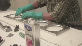
Prepared the ribs and stiffeners for paint by first removing ink and residue with acetone, then washing with dish soap, and then scrubbed with Ekoetch 2:1 using medium Scotchbrite pads.

The paint is Ekoprime diluted 10% with distilled water and applied using a HVLP electric sprayer. Ekoprime settles in the can quickly and needs to be stirred often. A solid sludge will form in the can after just a day or so.

The weight of the paint adds an additional 4.35%. This was calculated by weighing the nose ribs before and after painting. I’ll repeat this on other wing parts to see if this holds true.

Practiced riveting using the bench-mount squeezer from aircraft-tool.com. Made some practice pieces which were riveted, drilled out, then riveted again.

Riveted rib stiffeners to nose ribs. The bench-mount squeezer gives consistent results.

Here are a couple of short videos which highlight the steps:

https://youtu.be/MGYRM3ycstU
https://youtu.be/h5hzgzNQvxM
 

Attachments

  • photo10525.png
    photo10525.png
    1.2 MB · Views: 0
  • photo10526.png
    photo10526.png
    1.2 MB · Views: 0
  • photo10527.png
    photo10527.png
    934.8 KB · Views: 0
  • photo10528.png
    photo10528.png
    1.4 MB · Views: 0
  • photo10529.png
    photo10529.png
    1.1 MB · Views: 0
  • photo10530.png
    photo10530.png
    1.3 MB · Views: 0
  • photo10531.png
    photo10531.png
    1.3 MB · Views: 0
  • photo10532.png
    photo10532.png
    1.3 MB · Views: 0
  • photo10533.png
    photo10533.png
    1.1 MB · Views: 0
  • photo10534.png
    photo10534.png
    817.4 KB · Views: 0
  • photo10535.png
    photo10535.png
    800.9 KB · Views: 0
  • photo10536.png
    photo10536.png
    1.4 MB · Views: 0
  • photo10537.png
    photo10537.png
    1 MB · Views: 0
  • photo10538.png
    photo10538.png
    634.2 KB · Views: 0
  • photo10539.png
    photo10539.png
    835.7 KB · Views: 0
  • photo10540.png
    photo10540.png
    1.3 MB · Views: 0
  • photo10541.png
    photo10541.png
    1.2 MB · Views: 0
  • photo10542.png
    photo10542.png
    1.3 MB · Views: 0
  • photo10543.png
    photo10543.png
    886.9 KB · Views: 0
  • photo10544.png
    photo10544.png
    1.1 MB · Views: 0
Last edited:
Finished riveting the rib stiffeners. The ribs are now ready for assembly, except most if not all ribs will be trimmed for length (depending on location) and the nose ribs leading edges will be trimmed after fitting the skin. Also there will be some paint touch-up to do, mainly on cut edges.

Riveting the rib stiffeners is likely the easiest riveting for the entire project; bigger challenges to come. But the bench-mount squeezer makes this step a breeze. I fabricated a bracket mount for the narrow yoke (which came with the squeezer kit), to make it fit inside the smaller lightening holes.

The rivets themselves are pretty consistent. Important to keep the work square to the dies. I have marked just a few to possibly drill out. I will try to get my EAA Technical advisor in soon to check my work and talk about tolerances.

Here's a link to a short video which hits the highlights:
https://youtu.be/BjzkMHSgAf4
 

Attachments

  • photo10737.png
    photo10737.png
    2 MB · Views: 0
  • photo10738.png
    photo10738.png
    1,019.7 KB · Views: 0
  • photo10739.png
    photo10739.png
    1.7 MB · Views: 0
  • photo10740.png
    photo10740.png
    1.2 MB · Views: 0
  • photo10741.png
    photo10741.png
    1.1 MB · Views: 0
Last edited:
Those ribs look like factory Frank, You do great work. When I built my Rv4 wings I used the scotch brite wheel but I used it in my drill press with the horizontal orientation. That also seemed to work well. But as you said if not careful it would snatch it out of your hand and throw it across the shop.
 
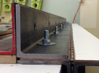
Milestone achieved with the bending of the spar C-channels and joggling the ribs. I should have followed Dave Clay’s plan (google: dave clay bending brake) more closely in some respects. Immediately discovered two four-foot nickel steel hinges were inadequate. Replaced with one six-foot stainless steel hinge (with two one-foot pieces of the nickel steel cut for the ends). Need that single solid piece across the middle. The straightest of the 3x3 steel angles was used for the bending edge (there was some bowing of all the pieces). Though the apparatus flexes a bit under pressure, it has held up well. The results look good to me. EAA Technical Counselor is on the way to check it out.


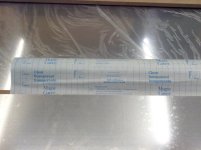
The aluminum sheets from Aircraft Spruce had some pretty heavy wrinkles and folds in the plastic film. A couple of edges weren’t covered at all. Rather than deal with the annoyance, I replaced a lot of it with protective film from the art store.

Though the 032 wing parts could fit on two 4x8 sheets, I bought three sheets and glad of it. I had a couple of sad results before establishing a ‘method’.

The joggling was easy after the joggle blocks were made. Paint on the inside of the joggle tended to come loose. Will take care of that and touch up the paint after the ribs are trimmed to length.

A short video covers the highlights:
https://youtu.be/PUgFZ8DvDVg
 

Attachments

  • photo11350.jpg
    photo11350.jpg
    897.5 KB · Views: 0
  • photo11351.jpg
    photo11351.jpg
    743.3 KB · Views: 0
  • photo11352.jpg
    photo11352.jpg
    596.7 KB · Views: 0
  • photo11353.jpg
    photo11353.jpg
    653.9 KB · Views: 0
  • photo11354.jpg
    photo11354.jpg
    1.1 MB · Views: 0
  • photo11355.jpg
    photo11355.jpg
    1.2 MB · Views: 0
  • photo11356.jpg
    photo11356.jpg
    865.1 KB · Views: 0
  • photo11357.png
    photo11357.png
    1.1 MB · Views: 0
  • photo11358.png
    photo11358.png
    1.1 MB · Views: 0
  • photo11359.jpg
    photo11359.jpg
    986.4 KB · Views: 0
  • photo11360.jpg
    photo11360.jpg
    961.6 KB · Views: 0
  • photo11361.jpg
    photo11361.jpg
    1 MB · Views: 0
  • photo11362.png
    photo11362.png
    964.2 KB · Views: 0
  • photo11363.jpg
    photo11363.jpg
    1.2 MB · Views: 0
  • photo11364.jpg
    photo11364.jpg
    613.8 KB · Views: 0
  • photo11365.jpg
    photo11365.jpg
    814.6 KB · Views: 0
  • photo11367.jpg
    photo11367.jpg
    1.1 MB · Views: 0
  • photo11368.jpg
    photo11368.jpg
    883.3 KB · Views: 0
  • photo11369.png
    photo11369.png
    1.1 MB · Views: 0
  • photo11370.jpg
    photo11370.jpg
    870 KB · Views: 0
Reality check: approximately 20 months into the project and total expenses are close to 4500.00.
Not captured in the pie chart is 262.00 for Stewart Systems. But there are a few non-project household expenses included.
The total does include the 12 foot cap strip material and its expensive shipping.
But still a few hundred dollars yet to spend on wing materials and tools.
Time spent on the project so far is roughly 1440 hours, based on 18 good months (72 weeks) of 20 hours per week.
I'm 68 years old and in good health. Colleen and I live on Social Security and retirement savings.
The expenses so far have been pretty well covered by our monthly budget.
Looks like the entire airframe can be constructed at this slow pace and rate of expense.
 

Attachments

  • photo11449.png
    photo11449.png
    74.3 KB · Views: 0
Ailerons are complete at this stage. Upcoming will be the addition of steel parts, alignment of trailing edge to the wing trailing edge, and fabric covering. And aileron hinge covers.

With more bucking experience and customized bucking bar, I will go back and replace or upsize a few rivets. So far I replaced/upsized maybe four rivets.

Pop rivets feel tight. Dimpling for the flush rivets enlarges the hole. Some of the shop head of solid rivets don't look exactly like the textbook diagrams.

There is a small pile of rejected pieces. Mistakes were made, even though the plans clearly state "Don't screw up".:)

Here is a five minute video:
https://youtu.be/88XLh21KJmg
 

Attachments

  • photo12457.png
    photo12457.png
    1.8 MB · Views: 0
  • photo12458.png
    photo12458.png
    1.5 MB · Views: 0
  • photo12459.png
    photo12459.png
    1.9 MB · Views: 0
  • photo12460.png
    photo12460.png
    1.7 MB · Views: 0
  • photo12461.png
    photo12461.png
    1.5 MB · Views: 0
  • photo12462.png
    photo12462.png
    1.7 MB · Views: 0
  • photo12463.png
    photo12463.png
    2 MB · Views: 0
  • photo12464.png
    photo12464.png
    2.1 MB · Views: 0
  • photo12465.png
    photo12465.png
    1.8 MB · Views: 0
  • photo12466.png
    photo12466.png
    1.7 MB · Views: 0
  • photo12467.png
    photo12467.png
    1.6 MB · Views: 0
  • photo12468.png
    photo12468.png
    1.8 MB · Views: 0
Hey Frank. that is a good looking set of ailerons. Keep up the good work and keep the pix coming, im sure Ill be referring back to them when I start my wings.
 
The wing spar webs and cap strips are laid out and marked. The lightening hole centers are marked. Aileron bracket holes marked.

The do-not-drill locations are marked.

Time to start cutting and drilling!

But which to do first: drill the cap strips or cut the lightening holes?

References here on the forum and elsewhere show builders mark and drill their cap strips (and spacer bars) first.

Then the lightening holes are cut and flanged (22 out of 35 on the LSA rear spar).

Another idea is to cut/flange lightening holes first. Then deal with any resulting warpage. One builder said this is what he did.

On the other hand, I can see building up the structure first, get it aligned and fixed. Then go in and cut out the excess weight.

Maybe no difference. Maybe just a matter of ease of material handling.

Just another happy puzzle!
 

Attachments

  • photo13240.png
    photo13240.png
    1 MB · Views: 0
Regarding the LSA .032 root center ribs (no. 1 position), I talked to Bob and he said it is not necessary to flange the lightening holes.

"You don't need to. You can if you want but it's a lot of work."

My own reading of the plans led me to that conclusion also. But I see that factory kit wings do have those holes flanged. Some LSA builders have flanged theirs, some have not. Having visited another LSA builder a few years ago, I see from the pictures I took that he followed the plans and did not flange those .032 lightening holes. I will do the same.
 

Attachments

  • photo13484.png
    photo13484.png
    30.4 KB · Views: 0
  • photo13485.png
    photo13485.png
    1.8 MB · Views: 0
I decided to cut and flange the rear spar lightening holes before drilling for cap strips. Cutting the .032 holes with the fly cutter is actually a little smoother than cutting thinner material. But flanging the holes is more difficult in that the distortion is greater than with thinner material.

The result is a longitudinal bow and a transverse (up/down) bow. I'm not too concerned with the long bow, it's about 1/4 inch and requires very little pressure to flatten, so I think it can be handled in the assembly. The transfers bow was easily corrected with pliers. I used heavy tape on the jaws to protect the aluminum. My bob sticks were pretty worn out and the .032 just caused the wood to split.

My method of flanging the holes is pretty lightweight. I re-used a MDF die from the ribs and made a form block sandwich. Dressing the business edge of the die with sandpaper and cold beeswax between each hole helped a lot. The method works okay but in addition to the bowing distortion, pressing the flange also tends to cause the spar flanges to widen a bit at each lightening hole.

So, while the rear spar bends remained straight the edges of the spar flanges needed some correction to get back to 12 and 90 degrees. This was easily done with clamping and light hits from a dead-blow hammer.

With the main spars I am taking a different approach. Since those lightening holes will not be flanged, I don't expect any distortion. So I will drill cap strips first and cut lightening holes after. I am laying out the man spar with all cap strips on one side (rear) using strings, clamps and gauges to establish straightness and center-to-center distances. And I made a drill guide to use with a six inch bit which tested great and will make straight and perpendicular holes.
 

Attachments

  • photo13486.png
    photo13486.png
    1.3 MB · Views: 0
  • photo13487.png
    photo13487.png
    1.2 MB · Views: 0
  • photo13488.png
    photo13488.png
    1.1 MB · Views: 0
  • photo13489.png
    photo13489.png
    1.1 MB · Views: 0
  • photo13490.png
    photo13490.png
    1.1 MB · Views: 1
  • photo13491.png
    photo13491.png
    1 MB · Views: 1
  • photo13492.png
    photo13492.png
    1.4 MB · Views: 1
  • photo13493.png
    photo13493.png
    1.4 MB · Views: 0
My aviation adventure of the week: getting the left wing spars together.
I found that the 2X riveter is not strong enough to do AD5 rivets.
So I need to check the cfm output of my small compressor against the needs of a 3X or 4X rivet gun.
 

Attachments

  • photo14697.jpg
    photo14697.jpg
    1.3 MB · Views: 0
  • photo14698.jpg
    photo14698.jpg
    1.1 MB · Views: 0
  • photo14699.jpg
    photo14699.jpg
    1.9 MB · Views: 0
Main and rear spars for the left wing are now substantially done. An EAA Technical Counselor visited and he went over every rivet with a flashlight and magnifying glass. He said my work was good but still found about twenty rivets to drill and replace. Having done that, I feel more confident about both the riveting and replacing rivets. Most of my problems were with the factory head. I learned that short rivets require less pressure than long rivets of the same diameter. And one long burst is better than three short bursts.

When bending the spar flanges on the brake, it’s important to pay attention to maximum bend radius as well as minimum. I exceeded the maximum and thus impacted internal parts dimensions. But Bob approved my fix and so I pressed on.

Basic sequence after the spar flanges were bent as follows:

Layout and mark front and rear spars together. Stack and clamp the cap strips together in position. Triple and quadruple check all marks and measurements.

Drill cap strips undersized using drill guides for plum holes. Cut and stack spacer bars at rib locations, lock into place and drill undersize holes with drill guide.

Spar attach and splice plates were difficult to cut using MDF template and flush router technique. Mostly cut these pieces with table-mount jig saw, hand saw and files.

Remake pieces as necessary to get good fit.

Cut lightening holes in main spar on drill press with fly-cutter.

Assemble the spars vertically mounted to bench, now with all pieces in their correct locations, front and back.

Cut rib attach angle blanks. Drill the rib attach holes only. Then bend the attach angles.

Using tape, square and clamps, drill the attach angles to match the spacer bars and cap strips.

Now that all pieces are in place (excluding wing strut attach fitting and its rib attach angles) , go through and drill to final size holes.

Disassemble, deburr and prep all pieces. Treat with Stewarts Eko Etch and paint with Stewarts Eko Prime.

Reassemble and rivet.

Flush rivet spacer to accommodate wing strut attach fittings.

Mark wing strut attach fittings and cut slot in spar flange.

Drill pilot holes for wing strut attach fittings. Hold in place with temporary screws.

Notch rib attach angles to fit over wing strut attach fittings.

This is where I will stop with the left main spar. When the time comes I will drill and ream the wing strut attach fitting holes for the AN3 bolts.

I’ll also remake at least one of the rib attach angles over the wing strut attach fittings to get better edge distance for the ribs at that location.​

Here's a short video:

https://youtu.be/ibsnJjDfwvQ​
 

Attachments

  • photo14893.png
    photo14893.png
    2 MB · Views: 0
  • photo14894.png
    photo14894.png
    198.3 KB · Views: 0
  • photo14895.png
    photo14895.png
    1.3 MB · Views: 0
  • photo14896.png
    photo14896.png
    1.2 MB · Views: 0
  • photo14897.png
    photo14897.png
    1.4 MB · Views: 0
  • photo14899.png
    photo14899.png
    1.3 MB · Views: 0
  • photo14900.png
    photo14900.png
    1.4 MB · Views: 0
  • photo14901.png
    photo14901.png
    1.7 MB · Views: 0
  • photo14902.png
    photo14902.png
    1.9 MB · Views: 0
  • photo14903.png
    photo14903.png
    1.9 MB · Views: 0
  • photo14905.png
    photo14905.png
    2.2 MB · Views: 0
  • photo14906.png
    photo14906.png
    1.5 MB · Views: 0
  • photo14907.png
    photo14907.png
    1.7 MB · Views: 0
  • photo14908.png
    photo14908.png
    1.7 MB · Views: 0
  • photo14909.png
    photo14909.png
    1.8 MB · Views: 0
  • photo14910.png
    photo14910.png
    1.6 MB · Views: 0
  • photo14912.png
    photo14912.png
    2 MB · Views: 0
  • photo14913.png
    photo14913.png
    1.8 MB · Views: 0
  • photo14914.png
    photo14914.png
    2 MB · Views: 0
  • photo14915.png
    photo14915.png
    1.8 MB · Views: 0
Last edited:
Three of the four wing spars ready to go. The fourth (right main) is ready for etch and prime, with warm temps forecast for Tuesday this week. Perfect timing! :D
 

Attachments

  • photo15897.jpg
    photo15897.jpg
    1.2 MB · Views: 1
  • photo15898.jpg
    photo15898.jpg
    1.4 MB · Views: 1
All four spars are substantially done except for some touch up painting. But there are a few rivets I'm only let's say 85% confident of. I have drilled and replaced quite a few already. Sometimes the 2nd attempt is not much better than the first. Although I think these structures are very strong, I don't want someone to say "you really ought to replace those rivets" at some later stage.

So while I wait for a visit from at least one persnickety EAA technical counselor, I'm marking everything which could conceivably be a problem and then get expert advice. I am improving but the main problem is deformation of the factory head. You really have to keep your eye on the ball.

The main goal is to get a thumbs up on airworthiness of the spars. Only then will I tear down my elevated spar bench.

In the meantime, I can do some more rivet replacing, touch up painting, organizing and clean up. The plan for reconfiguring the shop for initial wing assembly is starting to take shape.
 

Attachments

  • photo16114.jpg
    photo16114.jpg
    1.6 MB · Views: 0
  • photo16115.jpg
    photo16115.jpg
    1.5 MB · Views: 1
  • photo16116.jpg
    photo16116.jpg
    1.8 MB · Views: 1
  • photo16117.jpg
    photo16117.jpg
    1.8 MB · Views: 1
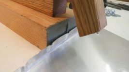
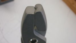
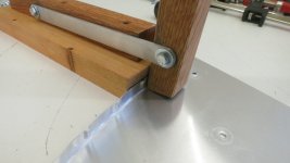
When it comes to preventing deformation of the factory head, a very helpful suggestion from Facebook Bearhawk group: use masking tape to get a better grip on the factory head. The other thing I am doing is cleaning the rivet set, hitting the contact cup with emery cloth to keep a slightly roughened surface, also to maximize the grip.

Another big help is I started to give support to the bucking bar, raising it as necessary so as to take gravity out of the situation. It's so much easier to keep the bucking bar in place when I don't have to hold it up!

Of course, before I started in with replacing rivets, I had to clean and reorganize the shop, throw out and recycle a lot of scrap. The anxiety around these spars was not helping!

And then set up a practice piece to rivet, drill out and rivet again.
 

Attachments

  • photo16195.jpg
    photo16195.jpg
    280.1 KB · Views: 0
  • photo16196.jpg
    photo16196.jpg
    1.6 MB · Views: 0
  • photo16197.jpg
    photo16197.jpg
    1.8 MB · Views: 0
  • photo16198.jpg
    photo16198.jpg
    1.8 MB · Views: 0
Two common errors I recently read from a professional, mis-alignment of the gun and rivet and a bounce between the rivet set and the factory head after trigger release. The fixes are to 1) point at the rivet with your index finger on the gun hand to help keep the gun in alignment, press the set into the rivet and squeeze lightly the trigger with your middle finger. Then keep pressure on the gun for a two count after releasing the trigger to avoid a bounce of the set off the factory rivet head which creates a smile on it.
 
Wing spars are done for now and hung up out of the way.


The spar rivets are generally shop-head facing forward and factory-head facing rear, unlike most Bearhawk examples I’ve seen. My research leads me to believe rivet direction was irrelevant with regard to the spars. This was a consequence of how the spars were set up on the bench and ergonomics.

In some cases the direction was reversed, the reason being I had better luck this way with some rivets of the rib attach angles. The shop head af the AD5 rivets had a tendency to deform the ends of these attach angles. I think the shop head forms from the center outward and the developing force tends to pull the metal toward the center. Unlike the factory head which has a larger bearing surface and the force is uniform. Replacing those few problem rivets and reversing the rivet direction mostly took care of the problem.

Drilling and replacing rivets turned out to be a fairly routine matter. Even so, there were maybe a dozen rivets between the four spars that I felt needed to be upsized after drilling them out.

I used the rivet cutter a lot. More than I would have expected. There are just too many in-between and impossible to calculate lengths to deal with.

I went over all of this with an EAA technical counselor and he had no issues.

The wing strut attach fittings are drilled undersized and held with hardware store bolts for now. I’m uncertain as to when I should drill, ream and permanently fasten those. The fuselage attach holes, also undersized, obviously will be drilled to final size when someday the wings are mounted.​
 

Attachments

  • photo16444.jpg
    photo16444.jpg
    229.4 KB · Views: 0
  • photo16445.jpg
    photo16445.jpg
    1.2 MB · Views: 0
  • photo16446.jpg
    photo16446.jpg
    1.6 MB · Views: 0
After the spars were hung up and out of the way the next item was to fabricate the two center ribs at the wing roots from .032 material. Although the factory apparently flanges the lightening holes on these two pieces, the plans indicate otherwise. I checked with Bob who said it’s really unnecessary to flange these holes. This plus the thicker/stiffer material makes it a lot easier to get a flat and straight rib.

It was a fun experience to pull out my old MDF templates, bender and backer boards, and make a couple of more ribs and the rib stiffeners. And what a pleasure it is to use the rivet squeezer on the AD3 rivets.

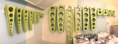
Now, finally, I have the complete set of ribs (plus a few extras), spars and ailerons and can start to reconfigure the shop for wing assembly.

I recommend having EAA technical counselors examine a project. I’ve had four visits so far. Though they won’t spend a lot of time with you, they will certainly address your concerns and point out any obvious defects. It’s a great feeling to get their thumbs up and be able to proceed with some confidence. And copies of their reports in the builder log will add to the seriousness of your efforts when it comes time for the FAA examination or in case you need to turn the project over to someone else.​

Linked here is a short video:
https://youtu.be/TP7E3ewnmFY​
 

Attachments

  • photo16447.jpg
    photo16447.jpg
    218.7 KB · Views: 0
  • photo16448.jpg
    photo16448.jpg
    229.6 KB · Views: 0
  • photo16449.jpg
    photo16449.jpg
    214.1 KB · Views: 0
  • photo16450.jpg
    photo16450.jpg
    193.4 KB · Views: 0
  • photo16451.jpg
    photo16451.jpg
    206.4 KB · Views: 0
  • photo16452.jpg
    photo16452.jpg
    255.1 KB · Views: 0
  • photo16453.jpg
    photo16453.jpg
    154.4 KB · Views: 0
  • photo16454.jpg
    photo16454.jpg
    184.1 KB · Views: 0
  • photo16455.jpg
    photo16455.jpg
    223.6 KB · Views: 0
  • photo16456.jpg
    photo16456.jpg
    248.7 KB · Views: 0
  • photo16457.jpg
    photo16457.jpg
    245.6 KB · Views: 0
  • photo16458.jpg
    photo16458.jpg
    261.2 KB · Views: 0
Last edited:
I cut the worktable down to 2X16 and did my level best. Reduced wing contact points to four supports. Focused then on using spirit level(s) and strings. Also rigged up a water level.

Thanks to sjt and his analysis of how to assemble the wing. Also, videos from the factory confirmed the choice to assemble the center wing horizontal on the table. After preliminary assembly, the center wings will then be set up parallel in vertical jigs.

At first I wondered why Bob would specify the aileron support frame in decimals… 3.78 rather than fractional. But if you subtract front/rear webs and cap strips (for that location) from the nominal front/rear dimension on the mylar (31.0), then that is the exact result.

All the center ribs were initially cut to the same nominal front/rear dimension (31.0). For assembly, I subtracted cap strip thicknesses from either end of the center ribs as required by each rib station. Also subtracted 1/32 from each end for wiggle room.

Aviation snips removed the wider bits. Then bench grinder to the pencil line, hit it with flat file and scotch-brite wheel. The trimmed ribs don’t just drop into place. It requires some relaxing of clamps and loosening the structure to allow the ribs into place.

The center ribs don’t fit tight against the spars and cap strips. But the edge distance for riveting is more than adequate.

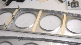
The spars and ribs of the left wing are now set up in a basic configuration held together with clamps.

At this point the aileron support frame is only mocked up. It is the correct dimension and square. But points to the fact that I need to get started on welding asap.

After triple checking for flatness and level I will go ahead and start drilling. I have a nice compact air drill to use but my little air compressor isn’t up to the task. So at the moment I’m shopping around for a suitable air compressor. My research indicates the basic requirement for an air drill is about 5 CFM.​
 

Attachments

  • photo16706.png
    photo16706.png
    2.1 MB · Views: 0
  • photo16707.png
    photo16707.png
    1.6 MB · Views: 0
  • photo16708.png
    photo16708.png
    2 MB · Views: 0
  • photo16709.png
    photo16709.png
    2 MB · Views: 0
  • photo16710.png
    photo16710.png
    2.1 MB · Views: 0
  • photo16711.png
    photo16711.png
    2.2 MB · Views: 0
Hey Frank, those wings are looking good. It looks like you will be skinning them soon? I looking forward to getting started on mine. Im almost done with the fuse, I still have a few things I want to get done before I start the wings. Im thinking about making the cap strip a one piece milled out of a solid billet of aluminum. My son is a machinist and we have a bridgeport mil. I think Mark had someone build a cap strip like that but I dont think it went anywhere. If I do it ill share it on the forum here.
 
Wow Dave that's quite an idea! But if you have the means to do it then go for it. Tell Bob and see what he thinks about it.
Me skinning soon? Not likely. Currently left wing center skeleton is riveted and set aside. Now beginning the same for right wing.
Then both to be set up side by side in vertical jigs for nose and back ribs.
Then there will be a stretch of time while I make the steel parts.
I don't suppose you already have the steel parts for the wings, do you?
 

Attachments

  • photo17008.jpg
    photo17008.jpg
    2.4 MB · Views: 0
Hi Frank, yes I have the steel parts already, I just bought them from Mark. I actually have all the parts for my wings I just need to get started on them but I want to get the fuse done first. Brooks Cone was saying that the factory is using the 1 piece spar caps. Im going to make a full spar assembly per the plan so I will have a good model of the spar to guide the making of the 1 piece spar cap.
 
Keep the steel parts handy, Dave. One of these days I’ll be bugging you for some detailed photographs. ?
 
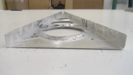
Assembled the center structure of the wings horizontally on the table. Then mounted them in a vertical jig for the addition of nose and back ribs. This will soon lead to welding of the steel parts which go into the wings. Here's a short slideshow/video which shows some details. https://youtu.be/tl4iSH3ONI8​
 

Attachments

  • photo17358.png
    photo17358.png
    2.1 MB · Views: 1
  • photo17359.png
    photo17359.png
    2.3 MB · Views: 1
  • photo17360.png
    photo17360.png
    1.6 MB · Views: 1
  • photo17361.png
    photo17361.png
    1.6 MB · Views: 1
  • photo17362.png
    photo17362.png
    1.7 MB · Views: 1
  • photo17363.png
    photo17363.png
    1.9 MB · Views: 1
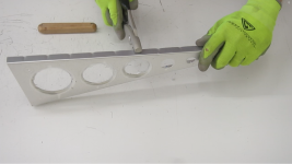
One builder years ago was a mill wright. He used string going thru the jig holes at the front of the nose rib to align them prior to match drilling them to the attach angles.
 
Great progress Frank. The wings look great. I have started working on my ribs. I am putting the stiffener angels on the flange side of the ribs. I dont know if the makes any difference which side they go on? Frank I am going to send your space back to you. Thanks for sending them. I will not be able to use the as I have decided to make my spar caps in one piece. I also plan to sell 2 more sets of one piece spar caps ill be making along with my set of spar caps. I look forward to seeing your progress.
 
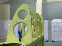
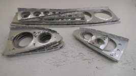
After assembling just the center wing (both spars and center ribs) I discovered this partial structure has a lot of flexibility. In the vertical jig it wants to sag, even between floor supports. Sighting along string lines, I found that adding even more floor supports helps to straighten it out. As far as getting to a straight and flat wing, without twist: it is fixed in the jig at three points and the fourth point is adjustable. In my case, the two root points are fixed, the tip is fixed at the main spar, and the tip at the back spar is free to move. Plumb bobs at the root, middle and tip were used to measure and make sure. Even with all the ribs now fastened the wings are still flexible. It's only when the skin is fastened that a rigid box structure will be achieved.

The nose and back ribs were originally cut to the nominal spar lines of the mylar drawing. I trimmed them according to the various spar cap thicknesses plus 1/32. I made sure the final ribs were not in actual contact with the spar web or cap strips.

I used various string lines to help guide the nose ribs into position. In the end, a string all the way trough the nose jig hole was useful. Also used a curve made from the master template the check the rib curvature and also a straight edge was useful.

Working with the back ribs in the vertical jig is an ergonomic challenge, being down on the floor. Raising the entire structure another 6 inches or more would have made it easier. Crouching on knees and getting the rivet gun into a good position is not easy. And typically, I only discover, late, that double-offset rivet sets are very helpful.

Here's a quick video:
https://youtu.be/ckJtSumW0fc​
 

Attachments

  • photo17951.png
    photo17951.png
    2.1 MB · Views: 1
  • photo17952.png
    photo17952.png
    2.3 MB · Views: 1
  • photo17953.png
    photo17953.png
    1.8 MB · Views: 1
  • photo17954.png
    photo17954.png
    1.8 MB · Views: 1
  • photo17955.png
    photo17955.png
    2 MB · Views: 1
  • photo17956.png
    photo17956.png
    1.9 MB · Views: 1
  • photo17957.png
    photo17957.png
    1.9 MB · Views: 1
  • photo17958.png
    photo17958.png
    1.7 MB · Views: 1
When you go to buy sheets for wing skin order 12 foot lengths and split in two to save money.
 
Hey Frank, great progress man! On my RV when I did the tip ribs, I used all-thread through the tooling holes to keep all the tip ribs in alignment. I used 1/4 20 all-thread and nuts. I had the same sag in the middle problem as well I did as you have done with that.. Another way I found to maintain the vertical alignment of the front and rear spar was to drill a small hole in each spar in alignment with the wing cord line and drop a string through it, as long as the string does not touch the sides of the holes the 2 spars will be in alignment.
 
Fourteen months and about 80 lbs. of practice pieces later, I'm now starting to make parts to be used in the aileron hinge hardware. Still learning, obviously. Tech counselor visits have been helpful. Most of what I am learning can't be put into words other than to say it's all about heat control; and heat requirements change rapidly even within the same joint, millimeter by millimeter. Good penetration often occurs a fraction of a second before burning a hole. So the heat control is a delicate matter.
 

Attachments

  • photo19785.png
    photo19785.png
    2.5 MB · Views: 2
  • photo19786.png
    photo19786.png
    2.2 MB · Views: 2
Back
Top