Tell us what you did today on your Bearhawk Project

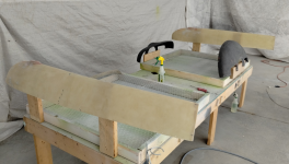
I've been a little lax in posting this, but I have officially started my build. Over the past few weeks I have been doing a bunch of woodworking. At this point I have a set of cutting forms and I am working on the forming blocks for the wings. It's not much, but it's the first step of a long journey. May the fun continue.​
 

Attachments

  • photo16083.jpg
    photo16083.jpg
    2.5 MB · Views: 0
  • photo16084.jpg
    photo16084.jpg
    2.4 MB · Views: 0
  • photo16085.jpg
    photo16085.jpg
    2.3 MB · Views: 0
Another scratch-builder! Three cheers for our particular brand of crazy! Looking good!

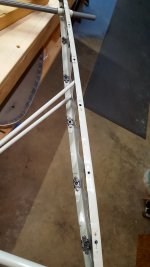
Having buried myself in MDF work for weeks as you are doing, I really enjoyed the process. One thing I wish I would have done before finalize those forming blocks and pressing/flow-forming up all my nose, center, flap, and aileron ribs was to bend the spars and tweak the flanges (hint: Fairmont MT114030 tongs... Cleaveland sells them, or your local sheet metal tool supply). Between adding joggles after the fact on the center wing ribs (was going to forego that, but thought better of it after seeing how unforgiving 0.020 skin can be) and variation seen in pressed versus flow-formed rib flanges, being able to tweak the forms for good fit would have saved me some time. Expect to have to further tweak for best fit, but you'll avoid wholesale rework and the potential for work-hardening/cracking stuff.

Also - having all of the jig pin locations in the master rib was really helpful in ensuring uniformity of those various templates, lightening hole press blocks, and forming blocks. I did not find need to do drill bushings for them, but not a bad idea.
 
Last edited:
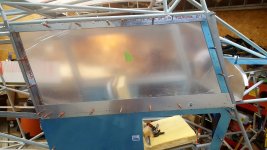
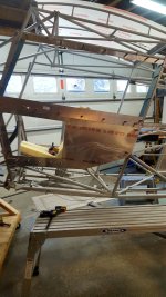
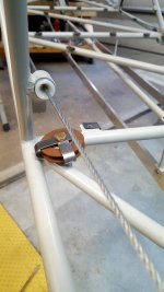
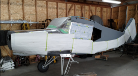
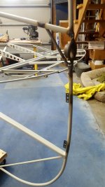
Had a productive week doing skylight lexan fit, window plexi cut/smoothed/installed into one window frame, and did long rudder cables from rear pedal to rudder horn.
Planning on fabricating a nutplate strip to fit in the square upper skylight formers to attach sides of the skylight - think the plan will work and I won't have to do nutserts.
window plexi in.jpg windowskylight.jpg rudder cables.jpg
door lower window.jpg
 
If you hadn't done so already, now would be a good time to make a template out of posterboard to show where your cables would exit the fuselage fabric enroute to the rudder horn. The future me found it was worth it's weight in gold when the time came to poke a hole in my brand new fuselage fabric.
 
photo16154.jpg Somehow, getting the wings buttoned up on a quick build assemble seems like a bit of a milestone. When a a friend like Dean, who is a scratch build addict (Mustang II, Wag-Aero clipped wing Cub), tutors and helps you on how to correctly buck rivets it makes for educational and wonderful time.
 

Attachments

  • photo16152.jpg
    photo16152.jpg
    1.7 MB · Views: 1
  • photo16155.jpg
    photo16155.jpg
    2.1 MB · Views: 1
Last edited:
Congrats Robin!
When it comes time to forming aluminum, don't do what I did. The first ribs I formed were the main nose ribs, and with that tight upper curve they proved to be the toughest. Start with something simpler or straighter like the flap ribs to get your process down.
 
Very nice. That's something I'd probably do next time around, having the smaller window panel in the lower door section. Certainly useful for manoeuvring on rough ground.
 
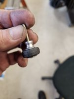
One of my last hurdles was trying to figure out a way to keep the front cargo door open. I've seen a number of ideas and solutions, but none that I really liked or wanted to mess with. A friend I used to work with years ago stopped by the shop yesterday afternoon for a long overdue visit and to have a look at my project. We talked for a long time, reminiscing about any number of things. As he was getting ready to leave I told him of my issue and asked if he would have any ideas. I told him of the door catch that Civil Air Patrol mechanics made for our Beavers. They attached to the wing lift strut. Not too complex to make, but a lot of work and that was my Plan A. We talked for awhile and then he came up with this dirt-simple concept! So, it's my turn to try and figure out how to make it and this is what I came up with. I finally settled on using a couple of tailwheels from R/C models I have hanging in my shop. After an afternoon of some simple lathe work and tweaking I now have a door stop! It's not much bigger than a fuel sump and if I end up changing my mind at a later date I can always go back to my Plan A.

20240407_114235.jpg 20240407_154335.jpg 20240407_154356.jpg 20240407_161115.jpg 20240407_163457.jpg 20240407_163634.jpg 20240407_163628.jpg
 
Engine mounting rubbers for IO 540 I have to decide between Lord and Barry mounts, can anybody give me their input on how Barry mounts are? There is a substantial price difference. How does the quality compare!
 
I can only speak to the Barry mounts and I haven't flown yet. I have had the engine mounted several years and there has been no detectable sagging so far. They were easy to install.
 
Woo hoo! Congratulations, Paul ! I'm hoping I'm only three or four months behind you (i.e. not in time for Osh this year, unfortunately)
 
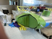
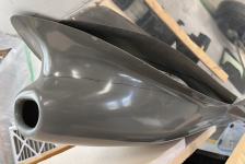
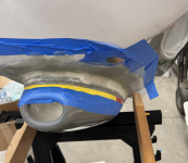
Prep for paint continues while I await warmer temperatures. Finally finished the fill/sand/fill/sand thing chin scoop, nose bowl, and exhaust air dam. Now it was time to figure out the masks for my paint scheme. All you guys who used single colour or straight lines on your airplanes are WAAAAY smarter than me....

Desired Outcome:
image.png​

Wing (the mask, when cut out, is for the blue bit. It is the only one needed)
image.png

Fuselage:
​image.png
image.png
image.png
image.png​​
​

​
 

Attachments

  • image.png
    image.png
    430.1 KB · Views: 0
That is really going to look sharp Mark. The flow and color combinations are striking. Can't wait to see it KOSH. If not this year maybe next.
 
Unlikely it will be at OSH this year. With painting, final assembly and inspection, remedial work (I'm sure there will be something), paperwork, and the test program, I don't think it is possible. That being said, one can always hope...
 
Did it myself just using Microsoft Paint. I scanned the 3-view from the plans and futzed around with 6 or 8 different designs. I did the same thing back in the day for my RV-8. Since this is a scratch-build (mostly), I heightened the panel of my Bearhawk which changed the glareshield angle so I modified the 3-view a bit to make it closer to what I built
 
Last edited:
With all these flight tests and painting, still soldiering along in my wing build (not jelly at all that you guys are flying...).

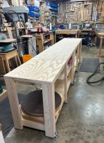
While my build buddy Carlo is already skinning his (wet) wings at the 8 month mark, I just finished building up and leveling sections 1 and 2 of the spar bench for handling flaps and ailerons. These are standard 5'3" x 24" x 32" modules that level independently than get a top made up of multiple layers of 18mm ply. All 2x4 stock and standard 4x8 sheets of 18mm ply 9although I joint and sand for a pretty, more uniform appearance). We won't need the wider table because we assemble the wing on a free-standing jig (see earlier post on that if interested), with just the spars, ailerons, and flaps being built up on the table. Once the ailerons and flaps are done, the third section of the table is added for wing spars, but in the meantime the two table sections do double duty as a long bench in the guitar shop (nice for load/unload).

Click image for larger version  Name:	IMG_0528.jpg Views:	0 Size:	304.4 KB ID:	89967 Click image for larger version  Name:	IMG_0528.jpg Views:	0 Size:	304.4 KB ID:	89967

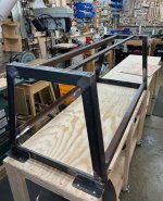
Need to do a little grinding and prime/paint on the stand seen on the table, then remount the wheels. This will take the 50" box and pan brake that was delivered Friday. I suppose another thread is in order for that project, but let me recommend Beaver Industrial Supply (BIS) in St. Louis... after Tennsmith could not deliver in under 4-6 months, and most of the other folks offering the BPB-1650 50" Jet B&P brake claimed either long delivery times (5 weeks +) or non-availability due to Jet's parent company ingesting a bending brake manufacturer, Beaver delivered in 3 days with best price ($2069), no shipping (even for residential delivery... versus Trick Tools' $480 shipping due to lift gate service). I even got this very cool t-shirt from them, and a real person on the phone when I called about availability. Super nice dude did the delivery, calling me a couple times during the day to keep me up to date on his ETA. Powered pallet jack took it up the driveway and parked it exactly where I needed it to get final measurements for the stand. Repurposed some crate material for the shelf below the brake... win-win.

Click image for larger version  Name:	IMG_0528.jpg Views:	0 Size:	304.4 KB ID:	89967 Click image for larger version  Name:	IMG_0528.jpg Views:	0 Size:	304.4 KB ID:	89967 Click image for larger version  Name:	IMG_0528.jpg Views:	0 Size:	304.4 KB ID:	89967

Looking at the BIS site this AM, looks like I scored the last 50" bench top 16 gauge brake, so the story from other suppliers of switch-over to new branding may be correct. Would def recommend BIS for other stuff.
 
Last edited:
Got a housing fixture (from Wag-Aero) for a rear tail light welded in to the rudder over the weekend. Also added tabs for nutplates in case I need to attach a rudder trim tab

Click image for larger version  Name:	rudder light housing.jpg Views:	0 Size:	694.1 KB ID:	90008
 
Very nice looking panel and workmanship! I hope I can make my current rats nest look a lot more like yours behind the panel.
 
Got the rear fuel lines run forward to the bulkhead "T"fitting. Made 3 sections line joined with 45 bulkhead fitting and rubber line. All removeable if required without disturbing exterior fabric.

right side fuel line run.jpg
 
I make no pretense trying to ​pass this off as relevant, other than to explain why I haven't touched the Bearhawk for the past few weeks. I thought I would post what I've been up to with my son. There's no way I could have pulled this off had it not been for the skills, tools, experience and patience I've gained from scratchbuilding the Patrol.

The best part is that my son and wife are now confident I can finish a project I started. :)

Answers to some common questions:
oxyacetylene
about 25 mph
6.5 hp, harbor freight
a little tight but fits adults
brake works
no clue where to take it, but we'll figure it out

Thanks for humoring me... Now back to installing nut plates.​

​​
​

​
 

Attachments

  • photo16478.jpg
    photo16478.jpg
    395.6 KB · Views: 0
  • photo16479.jpg
    photo16479.jpg
    298.3 KB · Views: 0
  • photo16480.jpg
    photo16480.jpg
    377.7 KB · Views: 0
Well, painting has finally started. Temperatures in our part of Canada are now warm enough to work in our unheated hangar. I built up a removable paint booth with giant tarps, floor model fan, furnace filter, and loads of light. I'm using Stewarts and boy-oh-boy has that been a learning experience. I am trying to follow the instructions to the LETTER, but unfortunately between the various versions of their videos on YouTube, as well as their printed instructions, there is some ambiguity on such things as gun pressure, viscosity times, etc. My lower cowl is about the only part that is perfect so far. Everything else has some level of orange peel although you have to be quite close to see it. I've been at this 3 weeks and I have done all of the various covers, intersection fairings, wingtips, horizontals stabs, panel, nose bowl, lower and upper cowl, cargo area rear cover, and the cargo doors. Man, there are a lot of bits and pieces.

Tomorrow I will do the elevators and rudder, then over the next few days the flaps, ailerons, and gear. Next week, wings, and the week after that, the fuselage.

image.png​image.png​
image.png​

image.png​

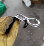
While watching the paint dry on my hstabs today I decided to make a couple of bolt on tow hooks for the main gear. I'm suspecting that it won't be too many years before I will need to use the John Deere lawn tractor to haul the Bearhawk out of the hangar (I currently use it to pull my Maule back into the hangar as there is a little bit of a slope and it is all grass). I just went to the hardware store and bought a couple of giant eyelets, bent up some scrap 4130 sheet, welded it together and drilled a couple of holes. It was nice to do something other than fill/sand fiberglass or prime/sand/clean/paint.

image.png​

image.png​
 
Well, painting has finally started. Temperatures in our part of Canada are now warm enough to work in our unheated hangar. I built up a removable paint booth with giant tarps, floor model fan, furnace filter, and loads of light. I'm using Stewarts and boy-oh-boy has that been a learning experience. I am trying to follow the instructions to the LETTER, but unfortunately between the various versions of their videos on YouTube, as well as their printed instructions, there is some ambiguity on such things as gun pressure, viscosity times, etc. My lower cowl is about the only part that is perfect so far. Everything else has some level of orange peel although you have to be quite close to see it. I've been at this 3 weeks and I have done all of the various covers, intersection fairings, wingtips, horizontals stabs, panel, nose bowl, lower and upper cowl, cargo area rear cover, and the cargo doors. Man, there are a lot of bits and pieces.

Tomorrow I will do the elevators and rudder, then over the next few days the flaps, ailerons, and gear. Next week, wings, and the week after that, the fuselage.

Stewarts could double their sales if they fixed this issue.

I am attaching a document from Stewarts that my Stewarts mentor passed along to me regarding the ProTek paint gun that replaced the DeVilbiss gun (that they use to sell, but was discontinued, and so all the material talks about that gun.) I followed these instructions to the tee after having orange peel issues. I reached out to my Stewarts Covering instructor/mentor and (now....I never ever painted anything before I painted my airplane. I knew nothing....I just took a class) I am very pleased with my results....no orange peel. No drips.

BTW, Orange peel is often a sign that the paint viscosity it too thick. Add more water to obtain a faster time in your viscosity cup. BTW, I have two guns, the small deVilbiuss one and the Pro-Tek gun. The Pro-Tek gun needed a thinner vicosity.

Screenshot 2024-06-03 at 5.17.46 PM.png Screenshot 2024-06-03 at 5.17.38 PM.png
 
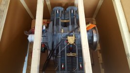
Received engine from Lycoming today...YIO-360, dual PMAGS, hollow crank. Crate is 44" x 40 " x 35.5" with a total shipping weight of 406 lbs. Took 12 months from ordering thru Mark and receiving on site.

Click image for larger version  Name:	YIO-360 crate.jpg Views:	0 Size:	815.9 KB ID:	90484 Click image for larger version  Name:	YIO-360 top view.jpg Views:	0 Size:	573.7 KB ID:	90485
 
Click image for larger version  Name:	IMG_4981.jpg Views:	0 Size:	1.67 MB ID:	90546 Click image for larger version  Name:	IMG_4981.jpg Views:	0 Size:	1.67 MB ID:	90546 Click image for larger version  Name:	IMG_4981.jpg Views:	0 Size:	1.67 MB ID:	90546
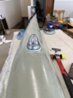
Working on installing Aero Sun VX lights in wingtip. The mount is for an RV 10. A bit like trying to make a square peg fit into a round hole. The NSP light mount didn’t turn out to bad. The masking will come off today. The next challenge will be forming the lens. Suggestions are welcomed.
 
alaskabearhawk I went to the link you put in the comments. The lens really look nice. I agree with you about the difficulty and why it is a road less traveled. Thanks for the log posts.
 
Last edited:
Started in on boot cowl, initial fit and trimming. Didn't anticipate having to pull the main landing gear off to get the side skins on! Overall fairly nice fit with minimal trimming apparent and no issues with the engine mount alignment, etc. Lotta questions coming to you guys though...:cool: Anyone put a removeable panel on boot cowl - somewhere on the side between the yellow tape lines I have in the picture below?

engine mount on firewall.jpg left side boot cowl.jpg right side boot cowl.jpg
 
Screenshot 2024-06-13 at 8.15.32 AM.png Screenshot 2024-06-13 at 8.14.46 AM.png

If you do it like I did on the left you will need a stiffener. I made it from .025 AL 2024. it is not straight. Mine had to conform to a slight bow in the metal.

My entire boot cowl and windshield can be removed with a screw driver by myself alone in the shop. I'm glad I did it this way. Contrast this with a very clean method of installing the windshield to the boot cowl with an epoxy adhesive and laying up a fiberglass fillet. Removal of the windshield will require a new boot cowl. I learned that method at a Sport Air workshop and glad to know it, but its not a method I want for my build....how can I say that without coming across arrogant and condescending....help me. Others that do it that way have a great appearance and no leaks when it rains. Probably quieter too.

I feel that a simple build with no avionics and a brake reservoir on the firewall does not need this (removeable side panels) and is lighter. I'm 60. I build alone in my shop at home. I find that my fabrication decisions are filtered through that lens.....meaning I want it so that I can easily service things alone when I'm 80. It adds time and weight.
 
I've got removable side cowls which give access to the standby batteries. I have removed a panel once during maintenance to get better access to the rudder pedals. My windshield can also be removed if necessary. The only section of my boot cowl that is riveted is the top part that the windshield sites on and attaches to the firewall. However I wouldn't say any of it is necessary. If it were all riveted in place the construction would be easier with no real downside.
 
Thanks Brooks...kinda in the same boat, work alone, slightly older and getting less flexible to crawl around out of position to fix things. Changing out a brake master cylinder would literally be a PITA (or back) it seems.
 
Experiencing some minor boot cowl issues, so made a window template and called it a day while I ponder the problem. My "coach" wanted his supper anyway :rolleyes:

Click image for larger version  Name:	window template.jpg Views:	0 Size:	1,001.8 KB ID:	90602
 
I really wish my boot cowl fit like yours does. I’m working on mine as well, but it’s an older kit, and is going to be quite a bit of work. The factory has obviously made big improvements in this area.
 
Temps and humidity this week preclude any painting (I'm using Stewarts) so I'm picking away at other jobs and ideas. Back when I built my flap handle I knew that I wanted to modify it so I didn't I have to fold my old man body in half to raise and lower the flaps so I added secondary handle. However, in the back of my mind I was thinking about when I retract the flaps and need to hold the button in I am still going to have to reach to the floor.

Well, with too much time on my hands and being tired of the paint thing, I did yet another mod on my flap handle.

image.png​
I now can just squeeze the lever and the button is depressed so I can get to the last two flap notches as well as completely lower the flaps. The spring down inside the handle pushes the button back out which returns the lever to neutral. I welded a little short piece of tube to act as a stop so the lever doesn't drop too far.

It seems to work great...on the bench. I'll know more when I get into final assembly in a few weeks and can try it out in situ. The good thing is that if it just doesn't work out, I can take the bolt out, remove the lever, and just cut the little tab off and I'm back to normal.
 
Quick trial fit of the prop today. End of the week might be ready to fire it up. Sorry start it up. Don't say fire. Trying to get my avionics sorted. Everything seems to be working but the GPS. Spent a bit of time with GRT tech support (excellent). Looks like a bad GPS.
 
Got the firewall formed using the methods laid out in Eric Newton's manual. It went pretty well, I may need to tweak the flanges a bit to get them to align with the cowling. Also need to enlarge the holes around the engine mount bushings so that they will clear the weld beads and the firewall will sit flush against the tubing.

IMG_0832.jpg
 
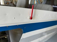
The standard window latch is nice and simple but I didn't like that the J hook inside tends to rotate down on it's own. If you are not careful you can slam it into the door skin. It seemed like just a bit of friction would hold it in place. A spring and a washer did the trick and now it stays in whatever position you leave it in.

IMG_4046.jpg
 
Wrapping the wings in vinyl was so quick, cheap, and light, I am not sure why i would do it any other way. A local RV7 owner wrapped his whol build, and it is beautiful.
 
Got some sanding and priming of parts over the weekend, made flap cables on Monday, got some outboard bungs and some grounding tabs welded into/on the fuel tanks.

primed parts.jpg
 
What surface preparation was needed before wrapping in vinyl? Alodine, priming? Or just a clean aluminum surface?
 
SInce moving into a hangar I share with a very small project I wanted to make and paint a few parts. A mechanic recommended a 20" box fan and 20" furnace filter duck taped to it. It is shockingly effective, including grinding fiberglass on a belt sander, and painting. Great cheap and temporary paint booth. I am not sure you couldn't paint a wing with 4-6 of these.
 
Stay with that set up for your small parts if you are sucking the contaminated air through the filter. Do not apply what I'm about to describe If your filtering air incoming to the booth.

The filters get clogged up fast when filtering air through a filtered box fan that is sucking bad air out of a booth when painting big parts. Then the air stops moving in the middle of painting and then my glasses get specks and then I clean my glasses..... then I think of the filter on my mask.
 
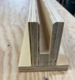
With the flaps at final prime and rivet stage, I moved on to the ailerons. Job One was the leading edge bending jig to give a smooth 5/16" radius (Patrol) where it is needed. I had a scrap section of the ply I used for the spar bench handy, and wanted to provide guidance for the 'blade' on what was a guillotine-style jig. I wanted a two-step bend process so that I could fine-tune the angle, but in retrospect, the springbuck on 020 is such that I could have gone with the sandwiched 2x4 method and gotten very close.

The first bend was set up to give a 90 deg bend, so I split a cleaned-up, clear 44" section of 2x4 at 22.5 deg and tacked that to the base. The objective of the base was to provide a blade guide and to prevent any spreading of the channel into which the blade was to go... I found I lacked enough scrap 2x4 to just add an outside double on each side of the V channel, so cut and glued in a bunch of channel depth 18mm ply gussets. Did some test bends and determine that parallel sides in the channel would get me to about 135 deg, so made up an insert that could sit atop the V channel. Also determined that getting the jig off the bench would allow some Bessey clamps to get the bend started in the 180 deg bend channel (a little Pledge and waxing the channel helps as well. I ended up trimming the sides a bit to go that on the long bends. Def overkill, but after 30 years in uniform, massive overkill is too often barely enough.

Click image for larger version  Name:	Bending Jig Base.jpg Views:	0 Size:	112.4 KB ID:	91077 Click image for larger version  Name:	Bending Jig Base.jpg Views:	0 Size:	112.4 KB ID:	91077 Click image for larger version  Name:	Bending Jig Base.jpg Views:	0 Size:	112.4 KB ID:	91077 Click image for larger version  Name:	Aileron LE Sections.jpg Views:	0 Size:	120.0 KB ID:	91078

Got the LE stuff bent and then fabricated the combination strong back and spar face brackets. These brackets align and clamp the spar to the bench to set the ribs and TE for drilling, then are used to build a strong back to ensure the LE skins go on dead straight and true. Having a strong back prevents any spar twist or bow that can occur if ratchet straps were used to pull the skins into place and worked well on the flap buildup. Once I wrap up my guitar stuff today, I'll get going got those ailerons. Will spread those brackets a bit wider to get more leverage, but photos give an idea of use with everything referenced to the bottom flange of the spar. The last shot shows the flap strong back in use, which helped get two very straight and true panels

Click image for larger version  Name:	Aileron Strongback Bracket 1.jpg Views:	0 Size:	104.3 KB ID:	91079 Click image for larger version  Name:	Aileron Strongback 2.jpg Views:	0 Size:	125.3 KB ID:	91080
Click image for larger version  Name:	Flap Strongback.jpg Views:	0 Size:	124.2 KB ID:	91081

Carlo is wrapping up his wings in the next week - wiring up the left wing (much simpler than the right with some avionics and autopilot stuff that needed to be sited and wired). We already ordered the fuselage/LG/tail tubing last week - will start building g up the fuse jig later this month. While I am still working through my sheet metal boot camp using the flaps and ribs, Carlo will be wings-complete in 10.5 months from receiving plans (less wing tips, which will be built up when we do the custom composite cowlings) - crazy progress for a scratch-builder. Should have the leading edge skin bending jig in hand in a day or two - this was based on the Bearhawk Factory LE bending jig seen in the factory videos, and was much faster and easier than vacuum bending for Carlo's skins. Will have shots and some measurements when it comes down to be stored here awaiting next use.
 
Last edited:
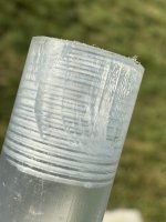
Re-made my site gauges. This is what it looks like when you over tighten a pipe thread fitting in PVC tubing. Interestingly, the internal cracks only appeared after a few months (maybe effected by heating/cooling cycles?)

IMG_4088.jpg
 
I should have started up my engine a few days ago. I stripped out an exhaust stud (rebuilt cylinders). Did fuel flow testing yesterday and today. I have a gravity fed small header tank (2L) right under the front right seat, and EFI pumps scavenging fuel out of that to a 45 psi fuel rail. I did gravity flow test to the header tank, and pumped testing (1.25X max fuel flow)

My gravity flows were a bit higher than most only because a nose high attitude changes the vertical distance very little, as compared to checking flows at a carb/fuel pump 4-6 feet forward, which rotates up when you position the aircraft nose up.

L only 34 gal/h
R only 33
Both >40, I stopped early so as not to make a mess

Pumped @45psi. EFI with a return line. Pumps put out less volume at higher pressure. I pressured the fuel rail, and measured the flow by the return line out the back end of the fuel pressure regulator. Again >40 gal/h.

Waiting for a heli-coil (tomorrow) cylinder is drilled and tapped for it. I have spark, fuel pressure, all the EFI sensors are functioning normally. Hopefully starts right up.

The only "issue" is I don't appear to be smart enough to program my EIS (GRT). Still trying to sort out a few sensors (ammeter and fuel pressure sender).
 
A more careful tapping and less tightening would likely work with rigid PVC but I'm going to switch to a flexible polyurethane (tygon/versilon).
 
I'm right behind you, John. Last week I installed my CHT, oil Press, Fuel Press, Manifold Press and Oil Temp sensors. I'm mocking up my plug wire route then will commit to the routing of my my EGT sensor wiring before I drill the exhaust to accept them. I think that leaves the Fuel Flow sensor.

My last update was Cowl Building. jsut the cowl, not the scoop, baffling, etc. I'm happy with it, and like the Piper Cowl Latches.

Since then I've completed my cowl scoop, Baffling, Baffle seals and oil cooler installation. I'm not a natural or experienced fabricator, need instructions and uncertainty often prevails in the environment of my mind as I work alone. It takes some time for me to figure things out.

That resulted in me having both a Vans Airbox & Cowl Scoop and a Bearhawk Airbox. The Bearhawk Box is stout and simple. I like that. But I went with the Vans box because I could see how and could develop a plan others had used to install it. I also was able to increased horizontally the exit area by about 1.5 inches, feel it will flow a bit better, and like the appearance. I hope I'll have good cooling.

Vans Cowl Scoop modification:
This is how it starts before I cut anything.
Screenshot 2024-07-08 at 12.49.55 PM.png
It hurt to cut out that much of my lower cowl. The next show has the scoop resting in place with its flange up inside. I love the mess I make. The fillet is shaped of an epoxy - Microballoon - cotton flox mix. I then apply the glass cloth over the fillet to form the flange. Its just a mess, isn't it!
Screenshot 2024-07-08 at 12.48.26 PM.png Screenshot 2024-07-08 at 12.48.35 PM.png Screenshot 2024-07-08 at 12.48.54 PM.png
We pop it off then trim it to size, sand and fill. I made the scoop removeable. Its installed with #6 machine screws and nut plates.

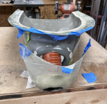
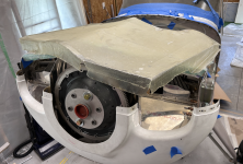
Screenshot 2024-07-08 at 12.50.38 PM.png Screenshot 2024-07-08 at 12.52.22 PM.png
 
The cowl scoop induction air intake....

My goal was a tight seal between the atmosphere and the airbox's airfilter to prevent leaks from pressurizing the lower cowl plenum below the engine. I also want the lower cowl to be easy to remove. Disconnecting the induction air intake from the cowl was a trick.

To do this I fabricated an inlet connection using SCEET hose. SCEET hose has a structural wire inside like a slinky that is encapulated between two layers of high temp hose material. When compressed it springs back and allow for misalignment. The hose fits into a tapered tube fabricated into the airbox intake. To install I press and twist the SCEET into the reciever and then secure the shell to the scoop with machine screws....they might be tinnermans...I forget. The second photo shows features the Shell and SCEET. The hose is received by airbox intake which has a slight taper so I get a tight fit.
Screenshot 2024-07-08 at 12.52.59 PM.png Screenshot 2024-07-08 at 12.53.20 PM.png
 
I'm not the smartest dude. Sometimes I get focused and loose the big picture. I wanted a plenum instead of Baffle Seals to seal the top engine plenum. I spent 10 days of shop time fabricating this plenum. Then I realized that the top cowl would have to be entirely removed in order to remove the plenum lid. That did not meet my design goal of easy maintenance. I just shake my head at myself....laugh at myself. Last year at this time I thought I would by flying by Oshkosh. No way!!

I like the method I dreamed up to fabricate it though. I covered the area with fabric, shrunk it to get the shape, then applied epoxy impregnated glass cloth over that fabric. I mean it was all trimed and attachment was done, fixed problem areas before I grasped the big picture.

Screenshot 2024-07-08 at 1.29.34 PM.png Screenshot 2024-07-08 at 1.29.48 PM.png
 
Back
Top