Tell us what you did today on your Bearhawk Project

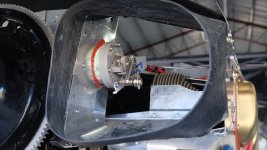
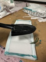
A goal is a tight upper plenum, so I first spent a lot of time sealing up the interface between the cowl intakes and the engine on the inside of the upper plenum. I fabricated a flexible fiberglass seal that is unporoven, but hopeful. If it works it will seal very well. Will it crack and not accomodate engine vibration? I dont know. But a single layer layup with my epoxy has ample flexibility....the data tells me yes.

The first photo is a veiw from inside the cowl looking over Cyl 1 and out the right intake. The airflow should flow smoothly into the top plenum due to the ramp I built up. The second photo shows the same part from a different view.

Click image for larger version  Name:	Screenshot 2024-07-08 at 1.37.52 PM.png Views:	0 Size:	4.42 MB ID:	91127 Click image for larger version  Name:	Screenshot 2024-07-08 at 1.38.05 PM.png Views:	0 Size:	3.01 MB ID:	91128

Click image for larger version  Name:	Screenshot 2024-07-08 at 1.38.15 PM.png Views:	0 Size:	3.40 MB ID:	91129

The Baffle seals.....McFarlane distributes a Baffle Seal material that is touted as the best by them for various reasons. Its quite expensive. Most folks use silicone seal material. The old saying "Thats a good price at half the cost." may not apply, but I found some for 1/2 the cost on ebay. I can say that I researched this on line and I think the photos of the McFarlane baffel seals exceed the industry standard in both the EAB and certificated arenas.

The second shot is a view taken looking in through the right intake looking aft over the right cylinders to the aft baffle. The yellow arrows point to gaps i got sealed up later. (click on the second photo below to show an expanded view) The red arrow shows a gap that it typically overlapped like the one on the far right, but was trimmed and treated to seal up any air leaks.

Click image for larger version  Name:	Screenshot 2024-07-08 at 1.38.28 PM.png Views:	0 Size:	4.13 MB ID:	91130 Click image for larger version  Name:	Screenshot 2024-07-08 at 1.38.48 PM.png Views:	0 Size:	3.33 MB ID:	91131
 
McFarlane baffle seal is expensive but it works better and lasts longer than the alternatives. I used it in a Cessna 10 years ago and it still looks like new. I think it is worth it.
 
Interesting idea on the FG seals. Kevlar is even more flexible than FG, in fact they make CF-Kevlar-CF hinges, where the hinge material is just kevlar. cloth.
 
Wow! I've not played with Kevlar....your comment inspires the imagination. I just looked it up. Seems they treat the Kevlar with urathane. That would be cool to mess around with!
 
Last edited:
If this is the McFarlane baffle material that is scored on the side it makes contact with cowl, yes, it’s great stuff. Used it on my 182 and it does not transfer vibration to the cowl as the others do. I’ll use it on my Patrol.
 
SDS seems great, even if the "high school science project" wiring added months to the build. Before I hit the start switch, I already knew it would start because everything was showing working. I think Rotax has raised the bar for EFI, and the others will follow suit. But SDS quality is great, as is their customer support, the little that I have needed.
 
I will upgrade to a Gopro or similar for the 1st flight and afterwords. My cam phone just shows the prop cranking and starting. No engine leaks, but one brake leaking at the bleeder.
 
Finally completed attachment of engine controls to the fuel servo and attachment of the alternate air control cable About a year and and a half ago I ordered vernier assist throttle and mixture controls from McFarlane. Problem is I ordered 6 foot cables which turned out to be too long (not sure how I screwed up that measurement). I discovered this about 3 months ago when I tried to install them. I managed to talk McFarlane into exchanging them for 5 foot controls even though it was well past their return window. Problem was the new cables were back ordered two months. It wasn't immediately obvious to me how to secure the cables. Fortunately there were threaded bosses on each side of the cold air induction that I could install aluminum plates for the cable bracket mounts. I initially crossed cables in front of the firewall, this left the mixture cable too short. I then crossed them behind the firewall and that worked fine. Like most seemingly simple tasks this took a lot more hours to complete than expected.

DSCF2360.jpg DSCF2358.jpg DSCF2368.jpg DSCF2356.jpg DSCF2364.jpg
 
Second aileron framed up and just drill to size, deburr and dimple to go. Hope
to be alodyning and priming this weekend.
 
Last edited:
Completed my avionics wiring harness (Garmin G3X). I didn't trust taking measurements so laid up the wires between all the devices in place. I bundled them and removed the harness to the bench where it was way more easy to install the connectors. When I install the harness, I have 10-12 wires I will need to add to some of the connectors, that's why some of the DSUBs don't have the back shell installed yet. Besides the panel devices I have some boxes mounted on a panel on the back of the firewall. My ADHAR, pitch servo and remote comm are mounted under the front seats. The harness with connectors weights 4.0#, less than I thought it would.

DSCF2475.jpg
 
I did all my wiring as well which includes EFI. A lot of work. Surprisingly (to me) most of the labor was installing it all so it doesn't chafe/fatigue.
 
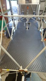
coin mat flooring.jpg Flyled Taildragger Max.jpg This past week I got my floordboards tweaked and trimmed after putting Coin Mat on and making fuel line and brake line pass-thru. Coin Mat is on the heavy side - likely would not do again, but the time and money has been spent on it so will press on as is. Also assembled and tested the Flyleds"Taildragger Max" light - (very nice, very very bright) for wing install. Likely will do one in each wing, once I figure out the mounting and wingskin lens fabrication
 
  • Like
Reactions: Nev
A bunch of metal fab work on the 0.032" gear leg closeout channels, upper LG straps in 0.063", the 30 degree/7/16" 0.080" radius bend straps for the aft gear and strut mount, and the straight and angled gear mount brackets for the fwd and aft gear mounts in 0.080". Most of these bends were air bends, which is to say a bend made into a V die or other non-bottoming die, so the correct combination of bottom die width would help maintain the pressed parabola close to the design radius. After playing with this on my HF 20 ton press with Swag Offroad standard 20" finger brake, I made up a design radius upper die as well to help things along. Both the 0.063" upper gear straps and the aft gear mount/strut mount 0.080 straps ended up right on the desired radius.

Click image for larger version  Name:	IMG_0895.jpg Views:	27 Size:	77.1 KB ID:	91650 Click image for larger version  Name:	IMG_0898.jpg Views:	32 Size:	136.8 KB ID:	91658 Click image for larger version  Name:	IMG_0895.jpg Views:	27 Size:	77.1 KB ID:	91650 Click image for larger version  Name:	IMG_0895.jpg Views:	27 Size:	77.1 KB ID:	91650 Click image for larger version  Name:	IMG_0898.jpg Views:	32 Size:	136.8 KB ID:	91658

For the gear mount brackets, I kept the bend radius to the minimum to allow as much of a flat as possible to take the 3/8" bolt head/washer and washer/nut. I did some test pieces to Bob's developed layout over a 7/8" bar mandrel with a hammer, and was not happy with the outcome. The lower tubing cut-out was problematic, so I went to a bottoming dies design using some scrap 1/2" plate for the base and some 3" pieces of 1" x 1" bar. The top die was made with some 7/8" square bar stock tacked onto a piece of the 3/4" x 3" bar that fits into the Swag upper die holder. I used this same 3/4" x 3 stock to get out the upper dies for the 9/16" and 7/8" diameter dies.
Click image for larger version  Name:	IMG_0925.jpg Views:	26 Size:	232.6 KB ID:	91660
Click image for larger version  Name:	IMG_0898.jpg Views:	32 Size:	136.8 KB ID:	91658 Click image for larger version  Name:	IMG_0925.jpg Views:	26 Size:	232.6 KB ID:	91660 Click image for larger version  Name:	IMG_0925.jpg Views:	26 Size:	232.6 KB ID:	91660

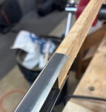
Finally, as mentioned in other posts, I bent the 0.032" closeout channels for the gear legs with the returns hammer formed over an interior oak mandrel.

Click image for larger version  Name:	IMG_0898.jpg Views:	32 Size:	136.8 KB ID:	91658 Click image for larger version  Name:	IMG_0895.jpg Views:	27 Size:	77.1 KB ID:	91650 Click image for larger version  Name:	IMG_0895.jpg Views:	27 Size:	77.1 KB ID:	91650
 
Last edited:
I used some marine grade stuff for my floor as it met flammability standards. I sure wish there would be an alternative, but protecting the floor and sound deadening on all that sheet metal is worth it.
 
Paul, that makes me feel better about going with the coin mat. This stuff is the aircraft certified stuff I got from a Part 145 shop that does aircraft interiors.
 
Was fun… have a few more pieces of hardware to do, but filling the fuse hardware box with what does not get welded into the gear legs. Waiting for fuse tubing delivery… we ended up at about $1800 each… not terrible for material these days.
 
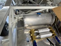
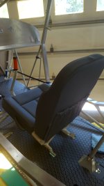
Haven't posted here in a while but have been progressing. With the trailing edges riveted on the ailerons and flaps, the conduit and wires installed in the wings and with the lights installed in the wingtips the wings are completed expect for covering, painting and installing on the fuselage . Still working with the lens for the ldg-taxi lights. I had the portion of the wingtip that I removed 3d scanned and then had my son 3d print a mold to form the lens, which I still have to do. It has been a learning process for an old guy. Installed the header tank, fuel pumps and filters under the pilot seat. (The seat cushions are from Sport Aircraft Seats and they installed nicely.) At OSH I picked up my motor from Mike M and the air-box from Brooks C. Really enjoyed visiting with both gentlemen.
I still have a lot of things to install on the IO 360 but have been acquiring pieces and parts that are ready to be installed. The airbox in nicely made but will take a little modification to work with the SDS throttle body. I have been pleased with the SDS system. It is finely crafted and like the Companion kit from Mark, the workmanship is excellent. Yesterday, I finally got around to working on the sight gauges again. It has been one of those items that I thought I had done then I read something on the forum that caused me to revisit them again. This time it was putting tubing around them to give them support.
I am about to start covering. Maybe it will look more like I have been doing something when people come and visit.
IMG_5260.jpg IMG_5234.jpg IMG_5237.jpg IMG_5271.jpg IMG_5227.jpg IMG_5229.jpg IMG_E4805.jpg IMG_5266.jpg
 
Installed the yaw servo. I initially had intended to just install the bracket, wiring harness and pulley brackets for this and see how the autopilot worked without it. So glad I changed my mind. I would have never been able to complete the installation once the boot cowl was back on. As it was it was a struggle for two of us to get the capstan bridle swaged to the cross cable. No room to operate the nicopress tool under the panel

DSCF2496.jpg
 
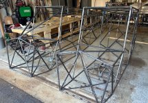
Milled out the fuse table components less the top last week... all of that 2x material is milled to 1.25" x 3.25" with four sides square, so it goes together without twist of other issues. On the spar bench, I ran my rails inside the legs, but because we wanted to be able to square our bracing structure for the tacked top and bottom, the upper and lower rails were run outside. There is another 24" long section that we will add for the bottom of the fuse, but given space constraints and the fact that Carlo's wife insists on parking her Tesla in what appears to her husband and myself to be a perfectly good workshop, that will have to wait, After bending up the upper 3/4" longerons, we blocked up the upper fuse and called it a night after a quick test-fit. On to coping out the rest of the upper tubing this week. FWIW, the free edge of the ply gets trimmed and routed flush to the rails once the fuselage frame goes 3-D.

Click image for larger version  Name:	IMG_0963.jpg Views:	0 Size:	188.8 KB ID:	91884 Click image for larger version  Name:	IMG_0964.jpg Views:	0 Size:	191.1 KB ID:	91885 Click image for larger version  Name:	IMG_0965.jpg Views:	0 Size:	200.6 KB ID:	91886 Click image for larger version  Name:	IMG_0964.jpg Views:	0 Size:	191.1 KB ID:	91885
 
Last edited:
More updates...

The top fuselage frames were welded up after coping, fitting, prep work (#30 holes for tube oil, deburr, polish), and tacking, and both are hanging over Carlo's garage benches.

Click image for larger version  Name:	IMG_0997.jpg Views:	0 Size:	179.7 KB ID:	92082

Carlo's hanger clean-up/wing work over the early part of the Labor Day weekend yielded a happy hanger mate (both RV and his Mustang II looking nicely free of spare airplane parts scattered underneath), a new bench, new vertical storage shelves which utilize more of the generously-sized full hanger, reduction of the horizontal filing system footprint, and some progress on getting his wings wired and all that detail work done.

Click image for larger version  Name:	IMG_0991.jpg Views:	0 Size:	230.1 KB ID:	92084

Both sets of landing gear were plumbed for brakes and the TE treatment was bonded on after priming. Worth noting is that - rather than form the TE ribs from sheet with the 20 ton press - Carlo decided to try welding the rib from .032 4130N flat stock with an aluminum heat sink... turned out well. We had decided to forgo the lower rib in favor of eliminating any catch-points for condensation and go with something closer to the current factory standard. The decision to avoid the second Adel clamp near the axle was based on Carlo's observation that bulkhead fittings are really happiest when installed in bulkheads, so the hard line down from the fuselage flex line to flex line to the brake goes bulkhead to bulkhead. Axles will wait until the fuselage is welded and on the fuse rotisserie for final alignment and tacking... there will be some grinding of primer to do, but the ability to tweak things supersedes a little extra weld prep work. BTW, we cut that axle relief with a mini-mill using a tilt table jig to set the required double-angle... have a shot, but have to fish it out of the camera. The step is not well-represented in this shot, but we went with some scrap streamline for the upper arm and round for the lower, with the actual streamline step and end-plate to be cut and welded after the aircraft is on its gear (along with the axles!).

Click image for larger version  Name:	IMG_0997.jpg Views:	0 Size:	179.7 KB ID:	92082 Click image for larger version  Name:	IMG_1016.jpg Views:	0 Size:	165.1 KB ID:	92089 Click image for larger version  Name:	IMG_0997.jpg Views:	0 Size:	179.7 KB ID:	92082
Sunday was consumed getting the modular table extended to 18' with a cantilevered add-on (the table system is built in 2' increments, with the current two 8' x 34" standard modules sufficient for upper fuse). We could have done a single 24" full table module, but the cantilever was easier to do and preserved some access for the foot pedal and torch connections. Once that work was done, Carlo worked late Sunday and Mon AM to get the lower longerons spliced and bent in the horizontal plane while I built up the standoffs for welding the back side of the lower frame while clamped to the table (the shock strut/front seat base frame needs clearance) and a few other wood and ply-based jigs.

Click image for larger version  Name:	IMG_1016.jpg Views:	0 Size:	165.1 KB ID:	92089 Click image for larger version  Name:	IMG_1016.jpg Views:	0 Size:	165.1 KB ID:	92089 Click image for larger version  Name:	IMG_1016.jpg Views:	0 Size:	165.1 KB ID:	92089

The weekend also saw the reincarnation of the aileron leading edge skin bending jig discussed previously. The first version was disassembled and ply used for other projects, so when Carlo became a bit dissatisfied with the fit on one small section of his right aileron, I got a chance to do SkinBender 2.0, shrinking the footprint and reducing the materials requirement to a half sheet of 18mm ply and a single 2x4, as well as reducing the component count and improving ease of build. I will do an article on this second jig, as it really does make a perfect bend for the aileron a very quick thing.

With Carlo home on Tuesday and free from other responsibilities, I burned a day of vacation and we worked on the lower frame cutting/fitting/tacking job (which included some very good demos of repair techniques as I got used to the pulse feature on Carlo's SquareWave ... my Everlast has a flex head CK torch and very different pedal feel, so that's my excuse for those burn-throughs while tacking the thinnest wall stuff)... I did get better...slowly. By late afternoon, we had both lower frames ready to get the upper bend set between A and B, as well as start getting things welded up. BTW, Carlo borrowed a mini-mill for the coping, and that was a lovely tool to have to rough the ends, with cleanup done with the usual second cut carbide bit.

Click image for larger version  Name:	IMG_0991.jpg Views:	0 Size:	230.1 KB ID:	92084 Click image for larger version  Name:	IMG_1016.jpg Views:	0 Size:	165.1 KB ID:	92089

My plan is to take the welded upper and lower frames back down to my shop, then give Carlo a hand completing his fuse while we still have warmer weather (no heat in his garage or hanger). The blocking and fixturing developed should be readily transportable as are the built tables. In the meantime, I need to re-convert my garage from what was a 1992-vintage show office for a then-new former cow pasture community to a heated and air-conditioned space with the old 10' x 10' manager's office ripped out along with the wall-to-wall carpet. That should take me into October, which will get Carlo onto the fuse rotisserie for all that tabbing and gross layout on seat frames, etc. underway, and the build table knocked down and transported to my place. With heat in my garage, I can weld over the winter to get my own airplane on gear by the spring and back to the wing build-out.
 
Last edited:
Unfortunately I had the opportunity to find out if my roll servo mounted in the wing was actually removable through the access openings. Fortunately it was, although with a lot of difficulty. I couldn't remember when I installed it with the wing open if I had actually checked to see that it was possible to remove the four fasteners. While configuring the G3X system I discovered that the roll servo was not talking to the system. Talking to Garmin experimental support they said to check the status light. I had to buy a telescoping mechanics mirror just to see it and it was not lit meaning either there was no power or the servo was bad. I connected another servo to the connector and verified the wiring was fine. I had made the mounting system using Garmin's generic mount as a starting point. I will make a couple modifications to it that will make installation back in the wing easier. I would say overall, I have not done a good job ensuring good maintenance access throughout the plane while building. Something to think about as you build. I have been very happy with Garmin's support while configuring the system, they have quickly responded to emails with lots of questions from me. Also pleasantly surprised that they have a one week turnaround on repairs. Cost is flat rate about half the cost of buying a new one. Something to consider while buying avionics is does there warranty period start at purchase or when you first fly. Most of my equipment is out of warranty before I fly.

Edited: I just found out after posting this, my servo is covered under an extended service life extension program, I get a free exchange servo! Surprised as I bought this about 6 years ago.

Click image for larger version  Name:	DSCF2520.jpg Views:	0 Size:	1.12 MB ID:	92119
 
Last edited:
Installed a taxi camera, fabricated a cover for my gascolator, made some small pieces to cover the splits for the portion of my glare shield that extends beyond the windshield, and fabricated a rudder tab. The $17 taxi camera has a better quality video than I was expecting, I was surprised it even worked, nice 170 deg view. A great safety feature. One of the downsides of going to 1/2" plumbing forward of the fuel valve was that the larger gascolator was too large to mount inside the belly, in fact it extended 1 5/8" below. Working through a list of mostly small tasks before I schedule the DAR.

Click image for larger version  Name:	DSCF2527.jpg Views:	0 Size:	761.4 KB ID:	92210 Click image for larger version  Name:	DSCF2510.jpg Views:	0 Size:	681.4 KB ID:	92211 Click image for larger version  Name:	DSCF2529.jpg Views:	0 Size:	1,012.0 KB ID:	92213 Click image for larger version  Name:	DSCF2529.jpg Views:	0 Size:	1,012.0 KB ID:	92213 Click image for larger version  Name:	DSCF2530.jpg Views:	0 Size:	539.8 KB ID:	92214
 
Last edited:
rodsmith Rod, can you provide me some info on the camera install when it's convenient? Type camera/brand/model, routing/interface to MFD? I would like to do same. Appreciate!

Dave (from Maine)
 
The camera brand is Raayoo, still available on amazon. I'm sure others will work also. Just make sure it is one that can convert to forward looking. This one came with two wire loops, cut one loop to make it forward looking, cut the other to remove the back up guide lines. It comes with two connectors, one for power and one for video. I cut off the power connector and installed a two pin connector and used shielded wire back to the main bus. I used the supplied video connector, bought a 6' RCA cable that connects to the PFD using a male BNC to female RCA connector. Both available on amazon. Routed the wiring under the cylinders with the starter cable.
 
pb, I thought I had posted pictures of the process, did a search and couldn't find it, Here's some photos, basically used pink foam and shaped it. Can't find a picture of the hole I cut in the cowling, it was big. Finish work took a lot of time.

DSCF1065.jpg DSCF1069.jpg DSCF1076.jpg
 
Templated, fit and fine tuning bulkhead in cargo area. Decided to use Kydex material which is easy to work with but seems a bit heavier than Al and certainly a bit more $$

Kydex cargo bulkhead.jpg
 
  • Like
Reactions: Nev
I cast the aileron balance weights using the poured lead method. I had some lead bricks laying around from a previous employer, so no shortage of raw material. I was pleasantly surprised that a cheap second hand electric hot plate generated enough heat to melt the required amount.
IMG_5682.jpg IMG_5685.png IMG_5686.jpg
 
The fuselage builds continue apace, with Carlo's on the build table getting the vertical work done. I'm out for some travel next week, so he will be doing a bunch of work on brackets and other stuff, and we'll pull his out of the fixture around the 30th and get mine moving to fully tacked stage. Carlo does not have the luxury of a heated/cooled garage (wife insists on parking her Tesla inside of a perfectly good shop... crazy, eh?), so the clock is running on mid-Oct cutoff for welding up big stuff at his place. My garage is heated/air conditioned, so my welding and tabbing can hold off to winter... we will tack mine in early Oct and get it out of Carlo's garage so we can get his on the rotisserie to get as much done as possible before the cold sets in... hoping for a late warm snap through Halloween to stretch things.

IMG_1109.jpg IMG_1114.jpg IMG_1115.jpg

This past week I ended up building jigs and checking math during the day, then 3-4 hours each night up at Carlo's to get another station or two tacked in. We've been building up a rough-cut frame tubing kit as we've gotten his fuse filled out, so it should go a bit quicker the second time around. Laser shows pretty much dead center, so tacking up nice and straight.

IMG_1103.jpg

I usually can do physical layouts on the fly for most stuff like the bend in the E-M frames, but making up the jigs and fixtures usually takes my wood-focused shop (I build/repair fretted instruments in addition to the day job). For the C-P frame (which gets a 148.9 deg bend fore and aft and a 176.3 deg in towards centerline), I did a physical layout, checked it with the usual double angle math for 90 deg cases, and then did a layout in Fusion to triple-check (any of these would have sufficient, but my descriptive geometry is pretty rusty... result is 148.7 deg bend and 23 and 27 inches CTC). Jig from bending brake crate scrap to check the cut before welding and tweaking after, plus a spacing jig (30" CTC > 29-1/8" long spacer mounted above the bend with tubes plumbed to Y-Z) to get the two C-P's precisely angled and allow a laser alignment with the fuse Y-Z.

IMG_1124.jpg

We needed the firewall framing to get the rest of the diagonals from C-P filled in, so another trip to Home Depot for some 18mm ply to get out the firewall frame cut/tack jig and the fixture to establish the rough 5.7 deg setback angle on that weldment (to be double-checked with a bob and laser). Hope to get both firewall frames welded, tweaked, and Carlo's tacked in with mount bushings and the T-8 diagonals later today.

IMG_1118.jpg IMG_1119.jpg

Carlo managed to tab out most of his lower frame before we did the 3-D build... brackets for the battery, engine monitor connectors, pedals and brakes, etc. got done without the frames in the way. Mine will get most of that stuff afterwards as I refine all the systems stuff. Also trying to provision for floats and cargo pod on mine, so that adds to the head-scratching.
 
The cheapest lead I could find was 5 lb fishing weights (ball shaped). My 2nd hand hot plate wouldn't melt it. But I took a cheap torch to the lead, melted just enough to cover the bottom of the old pan, and that did the trick. It melted right down. 4 bucks a pound was the cheapest I could find. I used epoxy/lead shot for the ailerons.
 
Carlo's fuselage got pulled from the table and my bottom and top frames got bent and we started jigging up. Carlo got enough structure in his fuse to avoid deformation... the cockpit diagonals will go in once the seating is ironed out (NOT going with Barrows design there...). Carlo hosting another Patrol scratch builder this weekend while he picks up aft spar caps and all of my wing tooling.

Click image for larger version  Name:	IMG_1150.jpg Views:	0 Size:	877.6 KB ID:	92359 Click image for larger version  Name:	IMG_1147.jpg Views:	0 Size:	1,003.5 KB ID:	92360

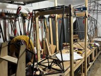
Proof that two Patrol fuselages plus wife's Tesla can all fit in one 20' x 20' garage with some creative work with Harbor Freight J-hooks and ratchet straps.

If you get by KFDK this weekend for the Frederick Wings and Wheels airport open house, look for Carlo's Mustang Too and a set of Patrol wings on the last hanger row north of the old tower building. And just because I was in Tampa earlier in the week and saw this mural on a building side, had to post it.

Click image for larger version  Name:	IMG_1150.jpg Views:	0 Size:	877.6 KB ID:	92359

Finally... after his Lincoln SquareWave ate its third board in 2.5 airplanes, Carlo borrowed my Everlast 255EXT while waiting for his Everlast 200DV to show. Big Green rocks. I loved the soft start on the Lincoln - almost distance-independent - but eating $800 boards at a better than one-per-airplane clip takes the edge off. I think Carlo liked my CK 17 flex head a little better than the Lincoln or Everlast stock 17's... ordered one up and is borrowing my 25' until his fuse is on the rotisserie.
 
Last edited:
Mounted park brake control knob. Seems like a good place. Aircraft Spruce has the park brake button decal that will label the function and operation of the knob.

Park brake control knob.jpg Park brake control knob 1.jpg
 
  • Like
Reactions: Nev
Good idea. I used the same cable mounted on the lower right instrument panel, so I can release it from outside by sticking my hand in the window. Yours does that while saving more panel space. Coin mat on the floor looks pro. I used truck bed liner over self-etching primer from rattle cans. Hopefully it sticks and stands up.
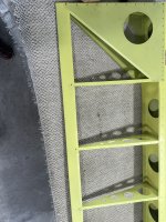
 
I wanted a cockpit indication of the cowl flap position. The Ray Allen position sensor can be hooked to the G3X to provide that information. Took some head scratching to figure out how to mount it. Realized that it needed to be mounted to a hinge to work as the cowl flap moves in and out.

DSCF2548.jpg DSCF2549.jpg
 
More 6-10 PM entertainment for Carlo's ever-patient neighbors as we tack and weld the second Patrol fuselage in his standard suburban front-load garage (some neighbors wander by to see the show; others shield their children's eyes to avoid those awkward questions ("Mr. Carlo and his friends make airplanes in his garage... what do you and Daddy make, Mommy?"). Sunday was a 10 hour day that got us from flat upper and lower frames to the aft three frames in. Monday PM saw the all but one of the vertical stations in as well as firewall. Tues PM got some of the firewall T-10 and T-11 fitted and tacked, as well as the last fuse station in and the diagonals tacked plus a good start on the wing mount/upper fuse framing. Shots from Monday PM... too busy last night to get the requisite pics... my daughter doubts progress...'no photos means it never happened.' Def have to drag her up to Frederick for show an tell before the weekend.

Click image for larger version  Name:	IMG_1153.jpg Views:	0 Size:	310.4 KB ID:	92426 Click image for larger version  Name:	IMG_1154.jpg Views:	0 Size:	319.8 KB ID:	92427 Click image for larger version  Name:	IMG_1157.jpg Views:	0 Size:	353.5 KB ID:	92428 Click image for larger version  Name:	IMG_1159.jpg Views:	0 Size:	393.7 KB ID:	92429

Carlo's fuse is hanging up over the milling machine and workbenches waiting for the build table to be broken down and my fuse moved down to my shop... great visualization tool for coping... I get to figure out the sequence of vertical mill cuts, make them just short of the marks, then use cutoff wheel, bullnose 5/8" carbide mill bit, and flap grinder to tweak. Might be an hour to get a tube fitted on both ends, but a lot fewer stops to get input from Carlo.

I went with the scratch-built Patrol over something like a Rebel or Cub clone because of the wide mix of materials and techniques necessary to get the airplane flying. My dad was fond of saying that '...the guy that dies with the most diverse set of skills wins, rather than a bunch of toys you cannot take with you...,' and what that is highlighting is how much I don't know. And that is a good thing, right? ;-)
 
Last edited:
Absolutely... and the head-scratching is reduced, or at least is more productive. I'd like to think I saved Carlo a bunch of time with my wing tooling and press setup when he did his wings, but right now, I am the one drinking from the firehose! We did pass the wing tooling on to another Patrol builder from Michigan this past weekend... not the full build-buddy experience, but I hope it helps Jake with the build and he in turn gets to pass that tooling on to yet another builder.
 
SpruceForest Nice work, fun to watch your progress. Have you any ideas how you may be implementing a hard point for shoulder seat belt attachment in the back seat? Curious...
 
SpruceForest Nice work, fun to watch your progress. Have you any ideas how you may be implementing a hard point for shoulder seat belt attachment in the back seat? Curious...

With both fuselage's primary structure tacked and mostly welded as of 11 PM last night, we were noodling seats and belts. Looks like completing the upper fuse frame 'X' between L and M would allow an inertial reel aft of the L-M frame mid-point (we already have an overhead anchor plate for the front seat reel) and a decent angle on the harness. Another option is cable anchors on the L frame, but that creates a bit of an issue for baggage, etc. What are you thinking about?

Seat looks like tube with CF/kevlar bucket... doing the vac bag mold right now. Carlo already laying up all his flooring in CF/Kevlar/foam, so not a bad idea.

Click image for larger version  Name:	IMG_1183.jpg Views:	0 Size:	1.04 MB ID:	92445 Click image for larger version  Name:	IMG_1184.jpg Views:	0 Size:	1.45 MB ID:	92446
 
Last edited:
SpruceForest I placed forward inertia reel at STA N cluster. Undecided for rear seat. I have a QB Patrol fuselage and I think the ideal place is as you depict. I would want to check with Bob Barrows about welding additional tubing diagonals first. Also considering tube clamps at STA M or STA L with a small attachment to hold shoulder harness webbing sans inertia reel. Thanks for posting! Dave
 
DBeaulieu It definitely adds some weight (~ 15 ounces for tubing plus the mount plate), but at 0.035 wall thickness, not as much as you would assume, and less than cable and cable anchors from the side frames. Bob's design methodology is the usual truss design, but notice the diagonals in the top and bottom frame aft of E-M, with upper and lower diagonal reversed to put them in tension/compression for fuse torsional loads. The X should not do anything beyond adding an additional degree of torsional rigidity there (already fairly stiff due to the cross-frame diagonals), but does provide a load path for the rear shoulder harness. Ideally, that pull is level with shoulders, but between range of torso height and getting a function anchor point, better than trying to beef the seat to the point where it takes that load.
 
In retrospect, adding just the aft half of the additional X provides enough structure to handle the shoulder harness load, although for the extra 7 ounces to close out the bay, I'll probably go with a full cross-piece.
 
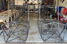
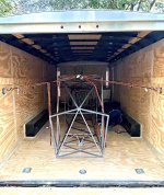
We got the forward wing mount-to-firewall frame diagonals in Thursday PM and set things up to move my fuse down to Germantown via another chapter member's 24' race trailer Sat PM (the trailer provider lives just south of me, and keeps his RV-9 and RV-10 at Frederick, so kindly volunteered to hitch the trailer up and do a run to and from FDK). Had to get the shots of both fuselages before the move, with mine going overhead in my garage (11' headroom, hung sideways still gives me 8' until I can do some demo and a new wall section to close off my 10' x 20' bay).

Over this AM to get the remaining T11 and T10 stuff into Carlo's fuselage, plus pick up his dynafocal ring to get that jig built.

Click image for larger version  Name:	IMG_1188.jpg Views:	0 Size:	395.4 KB ID:	92457 Click image for larger version  Name:	IMG_1189.jpg Views:	0 Size:	435.1 KB ID:	92459 Click image for larger version  Name:	IMG_1189.jpg Views:	0 Size:	435.1 KB ID:	92459
 
Last edited:
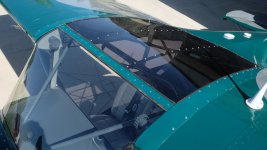
Final installation of glare shield, boot cowl, windshield and skylight (at least I sure hope it is final). I was going to rivet the boot cowl on, at the last minute decided to go with screws, drilled out the dimpled rivet holes for #6 cs screws. Will make any future removal much easier. I used a thin bead of Sikaflex 221 to seal the perimeter of the skylight and the top of the windshield. I used a healthy amount of it to seal the base and screwed down the windshield fairing before it set up. I removed the EFIS screens to access the screws from the underside while a friend installed them from the top side. Removed the protective coating from both sides of the windshield and was shocked at how clear it was, guess I had never looked through a new aircraft windshield before, hope I can keep it in good shape.

DSCF2567.jpg DSCF2569.jpg DSCF2570.jpg
 
Was hanging the fuse in the garage when I heard a little 'ting!' - I had missed a set of tacks on a side diagonal in one of the tail bays. Structure is redundant there, and still have to finish the welds on about 40% of the joints, but got my attention. Never got in an aircraft I did not walk around twice before cranking... not a bad idea for the build prior to major evolutions like moving/hanging wings, etc.
 
Weigh in day. With 6 gallons of unusable fuel and full oil, 1535#, 9.9" cg. I actually expected it to be heavier. A full skylight, full plexiglass doors, 30# of G3X system, leather seats, and 3" prop extension accounted for a lot of the extra weight. I also removed the rear seats and harnesses and weighed again. 1510# and 9.2" cg. I'm thinking as seldom as I would carry rear seat passengers, I may fly it as a 2 seater if it will save a significant amount in liability insurance. Tail wheel weight was 83 as a 4-place, 76 as a 2-place. While I had the scales weighted the tail wheel in 3- point, it is 150, sure feels heavier than that
 
Last edited:
I did the same not too long ago, and then realized I forgot to drill a hole up front for the GPS antenna.
 
I always planned to mostly fly with the rear seat removed, and have considered the insurance thing also. I haven't asked for a quote yet. My tail was almost exactlhy double in the 3 point as well.
 
Great looking work, I'll be building my fuselage soon. I would be interested in your experiences bending the longerons. Did you do it hot or cold? Any insite you can provide would be helpful. Working with steel tube is a skill I'm still developing.
Thanks
 
Yes Gerhard, got it through Mark Goldberg. Since it is a scratch built fuselage, I got the untrimmed windshield, vs the trimmed one that the QB kits use.
 
Carlo had the week I was down in Tampa to tab out his fuse... I will duplicate that in mine, but need a day to get the tabs sheared and drilled. I think my cabin floor will be a little different - still vacuum bagged CF/kevlar, but might do 3/16" foam and final layer of glass. Still noodling. Currently puzzling out the rudder cable routing and fairleads... not much to go by besides Newton's BH4 book and general practices (3 deg max; etc).
 
First engine run today. The mechanic that built my engine wanted to be present and it was a comfort to have him there. All went well. He adjusted the idle and idle mixture on the servo to get an idle of 700rpm. I tried slowly increasing rpm to full throttle but cylinder 6 alarmed at 400F at about 2500. Will put the cowling back on before running again.
 
Let me know if you need fairlead pictures. I had to add an additional fairlead to my Quickbuild fuselage to guide the flap cable underneath the seat mount. I think Carlo might be developing an overhead flap handle however.
 
Pitch servo mount.jpg I got done this week some final welding and painting on hardpoints for my pilot inertia reel and attachment for rear shoulder harness inertia reel plate.jpg inertia reel plate 1.jpg Made some s/s/ door strikers and mounted the pitch servo in place.
door striker small.jpg rear seatbelt shoulder attachment small.jpg tube clamp setup small.jpg
 
Last edited:
That was where Carlo thought his aft inertia reel mount would go. Are you happy with the angle from shoulders to the mount? it looks pretty decent, and no need to add tubes with required blast/prime/paint.
 
The angle is okay though not ideal IMHO (I hate to say it like that) I would have been happier if I could have moved the attachment aft another 12 inches or so. Was a compromise versus doing more fabrication on a finished fuselage. My solution is plenty stout...no worries there. Could be done a bit lighter with just using webbing loop straps and a thru bolt to hook on to.
 
Nice total weight. I was curious about where the 6 gallons of unusable fuel is sitting ?

Two gallons in each main tank and one gallon in each aux tank. I put a few gallons in each tank. While the plane was level, I pumped the aux tanks to the mains until the pumps lost suction, easy to hear without the engine running. I then used the electric pump to pump the mains out until they lost suction. After weighing, drained the tanks in the 3- point position and weighed the fuel from each tank. It was a nearly identical amount from side to side. Main tanks were just slightly under two gallons each, and aux tanks just under 1 gallon.
 
  • Like
Reactions: Nev
Moved the fuselage out of the garage and up to the hangar this A.M. I have a friend with a 18' slide bed tow truck which is just the right length for a Patrol with a Bearhawk tailwheel. Roll on, 4 straps and 13 miles later, safely at the hangar. Now in position to pin the wings, hang the tail feathers and adjust control rigging prior to cover. Likely running out of warm(ish) weather within the next month...
Hangar Move.jpg
 
I believe I may have the unenviable record for longest time to complete a Bearhawk. But I persevered and got it done. My first build log entry was 6-1-1999. It struck me that that is a quarter century ago, somehow sounds worse than 25 years. Received my special airworthiness certificate today.

DSCF2624-1.jpg
 
Congratulations Rod, impressed with your perseverance and fortitude in sticking with the project. A demonstrative first class example for us continuing builders as to what it takes to finish our projects. Hope you get some good flight testing and adventures in it!
 
Congratulations, Rod. Your achievement shows what can be accomplished if we keep our eye on the prize and refuse to give up. Hope your flight testing goes smoothly.
 
I'm real excited for you Rod! For context of your perseverance, In 1999 we were all excited about Y2K. We had 1 megapixle digital cameras, Apple just came out out with an Airport device to broadcast Wifi so we did not have to plug in. My sources say the first Beartracks Article came out in 1995 and the Patrol Plans were not available until 2002.
 
Last edited:
In 1999, I had just started work on my RV-8 which I finished some 17 years later, so I get it. Life gets in the way, but what a beautiful plane you have now! Congratulations!
 
Congrats! Sounds like an “award winning “ achievement!! Actually if you take it to OSH and it’s your first time, they give you a wood plaque the is an “ perseverance “ award. When we got ours I thought somebody “gets” it! Something else they started the last few years is that they will also sing to you. Now who wouldn’t want that!? Enjoy the fruits of your labor! DnD
 
Last edited:
I believe I may have the unenviable record for longest time to complete a Bearhawk. But I persevered and got it done. My first build log entry was 6-1-1999. It struck me that that is a quarter century ago, somehow sounds worse than 25 years. Received my special airworthiness certificate today.


That is amazing Rod...and congratulations! I'm really glad you stuck with it, if only to unseat me for the Red Lantern Award. :D Here's a blast from the past. You, me and Dan over at Dan's house for breakfast, Feb 2006 and November 2007!

Dan Rod and Me 02-06.jpg Dan Rod and Me 11-07.jpg
 
Back
Top