Hey Guys, I have a little more progress to report today. I got the fuel valve and gascolator installed, I had to weld 2 straps to the bottom of the front cross tubes to attach the valve and gascolator. I wonder if machine screws can be used with tinnerman nuts on floor boards? If anyone has tried that please let me know how it worked out. Thanks for the suggestion Jim, I know how much work those plate nuts are they are a PITA to install.

You are using an out of date browser. It may not display this or other websites correctly.
You should upgrade or use an alternative browser.
You should upgrade or use an alternative browser.
DavzLSA progress
- Thread starter davzLSA
- Start date

Hey Guys, I have more progress, I have the rudder cables made and installed for now. The one thing I found while doing that, making the cables that is, was all the cable need to be exactly the same length. If not the rudder pedal don't really feel right. So I had to make some of the cables more than once. I'm going to use a trim wheel so that will be the next time I will have to make more cables, this time it will be 1/16 cable not the 1/8 cable. Hope you all like the pics. There are some floor board pic here as well.
Attachments
-
 photo7195.jpg81.7 KB · Views: 0
 -
 photo7196.jpg56.9 KB · Views: 0
 -
 photo7197.jpg88.5 KB · Views: 0
 -
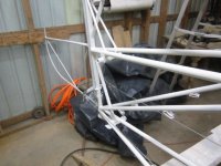 photo7198.jpg79.9 KB · Views: 0
 -
 photo7199.jpg96 KB · Views: 0
 -
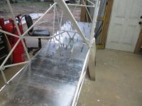 photo7200.jpg78.2 KB · Views: 0
 -
 photo7201.jpg74 KB · Views: 0
 -
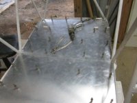 photo7202.jpg70 KB · Views: 0
 -
 photo7203.jpg60.5 KB · Views: 0
 -
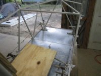 photo7204.jpg75.4 KB · Views: 0
 -
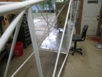 photo7206.jpg75.4 KB · Views: 0
 -
 photo7205.jpg74.1 KB · Views: 0
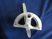
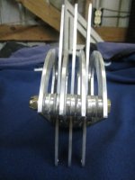
Hey Guys more progress thanks to the inspiration and beautiful job Spinningwrench did on his throttle quadrants I decided to do the same, I didnt completely steal his design, I put my own twist on it. I was pleased with the outcome and plan to build another for the back seat. I hope you all like the pics.
Attachments


Last edited:
HI Stinger I actually have 2 holes in each lever, you just cant see the top hole, I did that in anticipation of determining which way levers will have to be moved. If I need to use the top hole for the correct direction of movement Ill trim the bottom half of that lever.
Hey Fellas, got some progress to report, the dang elfs got in my shop again and made another throttle quadrant, it was just like the first one. Hope you like the pics. And may the shop elfs visit your shop too!!!
Attachments


Hey guys Im probably not going to me making too many more posts on my build for the next few months. I am building a 24x40 foot extension onto my shop. I need the space so I can build my wings. I having the slab and the outer shell of the building built by a contractor but I will finish out the inside of the building. As part of the building process I had to disconnect the power to the old part of the shop so Im dead in the water until I get the power back on and thats not going to happen until I get the new part built. So Ill be looking forward to seeing all your progress and I really like reading about new flights.
Attachments

Hey Guys, lots happened since my last post. I have retired from the evil empire (ATT) and now I am free to pursue my own interests. As you all know from my last post I have started building onto my shop hence I have stopped building on my LSA. Well I am about to be back to building on my LSA. My shop addition is almost complete now. I just need to build the benches and some shelving. I hope to start posting regularly soon on my LSA build. I have also started a business so that will take time away from my build but since I no longer have a pesky job to worry with I should be able to budget time for my LSA and my business. Here are some shop pics. Hope you like them.
Attachments


Wyo Johnson
Well-known member
I thought General Electric was the evil empire...
Nice space.
Andy
Nice space.
Andy

David Swartzendruber
LSA QB
Glad you're back! Looking forward to seeing your LSA progress.

Hi Guys, I have some progress to report today. I put the tail feathers back on my plane and got the flying wires sorted. I had to remake all the connectors because the store bought connectors made the wires too long. I also got my trim system in today. I am using a trim wheel so I had to engineer it since the LSA is supposed to use an overhead lever. I prefer the trim wheel so thats what I now have. Hope you like the pics. Happy building all!!!
Attachments
-
 photo8035.jpg3.3 MB · Views: 0
 -
 photo8036.jpg3.4 MB · Views: 0
 -
 photo8037.jpg3.4 MB · Views: 0
 -
 photo8038.jpg3.4 MB · Views: 0
 -
 photo8039.jpg3.5 MB · Views: 0
 -
 photo8040.jpg3.6 MB · Views: 0
 -
 photo8041.jpg3.7 MB · Views: 0
 -
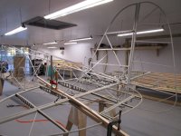 photo8042.jpg3.6 MB · Views: 0
 -
 photo8043.jpg3.6 MB · Views: 0
 -
 photo8044.jpg3.6 MB · Views: 0
 -
 photo8045.jpg3.5 MB · Views: 0

Frank
Well-known member
Sweet setup. Is the trim wheel system simple enough you make it dual? I assume the original overhead trim lever was located so it could be operated from both seats. Trim wheel definitely appealing. And the throttle quadrant (forgive my ignorance) is throttle, mixture and choke? Or carb heat? Something Corvair related? Anyway, looking great and the new place sure has filled up. 
HI Frank, The quadrant has a lever for the throttle, mixture and carb heat. The trim wheel could be set up for the rear seat to have one as well. The trim wheel is attached to a spool which the wire is wrapped around several times. For the rear trim control there would be a separate wire that would go from the front spool to a rear spool and from there another wire going from the rear spool to the trim tab control horns. I have found that the circumference of the spool determines how many turns it takes to move the trim tab up and down. The spool in my trim wheel is about 3 inches in diameter so it only takes 2 or 3 revolutions to move the trim tab from full up to full down. And I think the position of the elevator will affect that as well. I still may tweak it more the make the trim wheel less sensitive. I have started a little business in my shop as well, most of the tools you see are wood working tools. My new business is making outdoor furniture. Gook luck on your build Frank!!
Hi Guys, I remember seeing a excell spread sheet here somewhere that had all the materials for the lsa wing. I cant seem to find it again. If anyone knows where it is could you please point me toward it. I have not posted in awhile but I have been redoing my control column. I am rebuilding it with rod end bearings on the interconnect tube and bearings on the control stick axles, I believe it will make for a smoother control system. When I get it together I will post pics. Thanks All!!!
Last edited:
I just finished reading Franks LSA post. He had a table showing the materials he was planning on ordering.
I believe this is the post he had made...
https://bearhawkforums.com/forum/bearhawk-lsa-plans-build/57077-franks-lsa?p=57333#post57333
- Reuben
I believe this is the post he had made...
https://bearhawkforums.com/forum/bearhawk-lsa-plans-build/57077-franks-lsa?p=57333#post57333
- Reuben
Frank
Well-known member
Sorry Dave, I didn't realize that was what you were referring to, otherwise I would have replied. It is a preliminary list of parts (in Word not Excel) and a possible layout of the ribs and some other pieces, basically just enough to get me started. The parts list doesn't include the skins or steel items or fasteners.
My initial order from Aircraft Spruce (there will be others) was: 4 sheets 4x12 .020, 1 sheet 4x12 .025, and 1 sheet 4x8 .025 and the cost including 147.00 UPS to Denver was right around 1000.00. I'm hoping the wastage will be minimal.
In retrospect, I think that if you want to be as economical as possible and calculate the total order for aluminum, then you might start by laying out the largest pieces first and then proceed to the smaller pieces, i.e., layout (calculate) the skins first rather than last.
The .020 cuts easily with snips and the parts can can be very close to each other. The .025 cuts less easily and need some separation from each other, the cut edges being a bit wavy.
My initial order from Aircraft Spruce (there will be others) was: 4 sheets 4x12 .020, 1 sheet 4x12 .025, and 1 sheet 4x8 .025 and the cost including 147.00 UPS to Denver was right around 1000.00. I'm hoping the wastage will be minimal.
In retrospect, I think that if you want to be as economical as possible and calculate the total order for aluminum, then you might start by laying out the largest pieces first and then proceed to the smaller pieces, i.e., layout (calculate) the skins first rather than last.
The .020 cuts easily with snips and the parts can can be very close to each other. The .025 cuts less easily and need some separation from each other, the cut edges being a bit wavy.
Hey Frank, I have the spar and rib kit from Mark. All I really needed was the info on the cap strips and I have estimated the wing skins already. One of the things I found about the wing skins was that it will be difficult to estimate the amount of aluminum without a lot of waste. But from the widths of some of the skins the measurements dont lend themselves to a 48 in wide piece of stock.

stinger
LSA Builder
Hi Guys, I might suggest you modify the back seat. I have been in the back for around one hundred hours and it is terrible thus I changed the top bar and found it much better. My fourteen grand son is at the controls. Also the front seat needs a lumbar pad. Sending pictures. Stinger
Attachments


Hi Guys, I remember when I first started my build. I was frustrated with the plans of the control system. There were no pictures of the complete system. So after a lot of head scratching and talking to everyone I could find that had built an LSA I finally figured it out. I think the thing that would have helped me the most and relieved a lot of head scratching would have been some good pictures of the system from front to back. I have made some pictures of my build and the rear part of the control system in particular to share. Also here are the pictures of my alternative trim control system. I had a lot of friction in that system but I fixed that today. It seems that the torque tubes going though belcrank must be perfectly aligned. Otherwise if they are forced into the belcrank misaligned it will create lots of friction.
Attachments
-
 photo8412.jpg2 MB · Views: 0
 -
 photo8413.jpg1.8 MB · Views: 0
 -
 photo8414.jpg2.1 MB · Views: 0
 -
 photo8415.jpg2 MB · Views: 0
 -
 photo8416.jpg2 MB · Views: 0
 -
 photo8417.jpg2 MB · Views: 0
 -
 photo8418.jpg2 MB · Views: 0
 -
 photo8419.jpg2 MB · Views: 0
 -
 photo8420.jpg1.8 MB · Views: 0
 -
 photo8421.jpg1.9 MB · Views: 0
 -
 photo8422.jpg2 MB · Views: 0
 -
 photo8423.jpg2.2 MB · Views: 0
 -
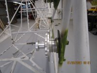 photo8424.jpg2.1 MB · Views: 0
 -
 photo8425.jpg1.9 MB · Views: 0
Last edited:

MitchG
Member
Hi Bill, the 2 coils are wired to the 2 sets of points, the output of the coils go through a passive coil switch. So which ever set of points you have voltage switched to is the one that fires its coil.
You mention a "PASSIVE COIL SWITCH". I understand the principal, but for the life of me and my "google-foo", I can not locate an example. If you could point me in the right direction it would be appreciated.
FYI...this comment is from post #14 in 2017 on page #1 of this thread.........I'm a little behind the times...lol
Last edited:
https://www.summitracing.com/parts/msd-8210 here is the coil switch
Hi Guys, I have some progress to report. I have finished fabricating my control column with bearings, it works very smoothly now. That was the second time I rebuilt it. I have the trim system tuned in so that it works smoothly now. I now have the stringers on now. I have a lot of pictures for this. The reason is that the plans show very little information on how they go on. So I think mine are on per the way Mark's LSA appears. I visited him in January and got a lot of pictures and measurements. I was also able to get a good look at how the rear windows were attached. The bottom of the rear window frames are attached to the top side stringer and there is an angel that runs along the top of the rear window frame which is not shown in the plans. In my pictures you can see where I have it test fitted. I will need to weld more tabs to attach the angle and parts of the frame. I bought the rear window frames from Mark and have not trimmed them yet so they are longer than the will be after installation.Comments and questions welcomed
.
.
Attachments
-
 photo8616.jpg2 MB · Views: 0
 -
 photo8615.jpg1.9 MB · Views: 0
 -
 photo8617.jpg2 MB · Views: 0
 -
 photo8619.jpg2 MB · Views: 0
 -
 photo8618.jpg2.1 MB · Views: 0
 -
 photo8620.jpg2.2 MB · Views: 0
 -
 photo8621.jpg1.9 MB · Views: 0
 -
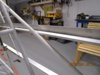 photo8622.jpg1.9 MB · Views: 0
 -
 photo8623.jpg1.9 MB · Views: 0
 -
 photo8625.jpg2 MB · Views: 0
 -
 photo8624.jpg2 MB · Views: 0
 -
 photo8626.jpg2 MB · Views: 0
 -
 photo8627.jpg2.1 MB · Views: 0
 -
 photo8628.jpg2.1 MB · Views: 0
 -
 photo8629.jpg1.9 MB · Views: 0
 -
 photo8630.jpg2.1 MB · Views: 0
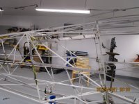
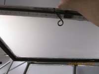
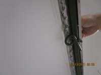
Hi Guys, More progress today. I got the back window frames attached. The plans show very little in the way of detail on this. I have documented the way I attached them with a little help from looking at Marks, LSA. The flat side of the frames faces the side of the fuse. I had to weld on tabs to attach the top angel and drilled the bottom of the frame to the top stringer. I also got all the stringers drilled to the cleats. All this info would have been nice to have starting out but I guess this is why I consider this build a journey not a destination. As usual comment and questions welcomed.
Attachments




BTAZ
Well-known member
Dave
I attached mine in a similar fashion.
When I covered the plane, the fabric wanted to roll the bottom of the window frame outward when I shrank it. I added a support bracket(angle off the stringer to an Adel clamp) on the diagonal tube that runs through the window area that tied into the stringer/frame.
You might want to weld on a tab to this diagonal that ties into the bottom of the window frame/stringer
I attached mine in a similar fashion.
When I covered the plane, the fabric wanted to roll the bottom of the window frame outward when I shrank it. I added a support bracket(angle off the stringer to an Adel clamp) on the diagonal tube that runs through the window area that tied into the stringer/frame.
You might want to weld on a tab to this diagonal that ties into the bottom of the window frame/stringer
hey Brad thanks for that advise I will do that. Mark was telling me also that some guys needed to open up the space between the frame pieces to be able to insert the fabric and the plexi glass. Did you need to do that or did the fabric shrinking take care of that; or does shrinking fabric just pull whole frame over?
Last edited:
BTAZ
Well-known member
Dave
I didn't have any problems putting in the plexi.after the fabric was in place.
Of course I don't know if my "joggle" is the same as what you have. I made my joggles using a typical Harbor Freight bead roller I had "upgraded".
It is best to put the two halves of each frame together with countersunk rivets with the flush head on the outside. I put mine together with the rivet tail on the outside and it just barely touches the fabric so can be seen as small bumps on the outside of the plane.
I didn't have any problems putting in the plexi.after the fabric was in place.
Of course I don't know if my "joggle" is the same as what you have. I made my joggles using a typical Harbor Freight bead roller I had "upgraded".
It is best to put the two halves of each frame together with countersunk rivets with the flush head on the outside. I put mine together with the rivet tail on the outside and it just barely touches the fabric so can be seen as small bumps on the outside of the plane.
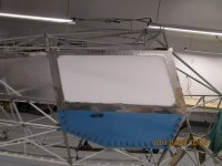
Hey Guys, I have some progress to report. I got my door finished and hung today. I also refitted my windows, I first built them in 2016. I put them in today and did not like the way they fit.So I completely rebuilt one of them and changed the position of the hinges on both of them. I've been working on this thing since 2015 so it seem like as I get more practice (5 years) I notice things that could be done better. Here are the pics. Hope yall like them.
Attachments
-
 photo8681.jpg1.6 MB · Views: 0
 -
 photo8682.jpg1.7 MB · Views: 0
 -
 photo8683.jpg2.1 MB · Views: 0
 -
 photo8684.jpg2 MB · Views: 0
 -
 photo8685.jpg1.9 MB · Views: 0
 -
 photo8686.jpg1.8 MB · Views: 0
 -
 photo8687.jpg2.1 MB · Views: 0
 -
 photo8688.jpg2 MB · Views: 0
 -
 photo8689.jpg1.8 MB · Views: 0
 -
 photo8690.jpg2 MB · Views: 0
Last edited:
Hey Guys, I got winders now. Check em out. Next up im going to bolt a plywood firewall to the front of the fuse and spot all the stuff that goes on the firewall, then transfer all that to the stainless steel firewall. Stay tuned.
Attachments


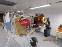
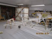
hey guys, I thought I would bolt on my wheels and engine and all the other stuff that would be in my way so i could spot all the other stuff that goes on the firewall. I hope y'all like the pix.
Attachments





interstate al
Junior Member
Looking good Dave!
Hey Frank, as soon as I get the firewall together Im going to start working on getting the engine and electrical system in. I plan to start it before I cover the fuse to check out the engine. It has ran before after I first built it. I took it down to Florida to William Wynne's place where he has a test stand.
Hey Guys,
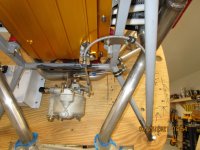
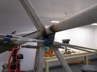
I have progress to report. For the last few days I have been working on getting my throttle and mixture controls hooked up. I thought going into this that it would not take long, oh boy was I wrong!!! I had to fabricate a million little brackets and figure out all the geometry to get it all to work correctly. I know it doesn't look like much progress but it was a lot of work. Anyway here are the pictures. Hope they are helpful to someone. Also rod end female bearing are on the way. I am just using the forks temporally just to get things moving.
I have progress to report. For the last few days I have been working on getting my throttle and mixture controls hooked up. I thought going into this that it would not take long, oh boy was I wrong!!! I had to fabricate a million little brackets and figure out all the geometry to get it all to work correctly. I know it doesn't look like much progress but it was a lot of work. Anyway here are the pictures. Hope they are helpful to someone. Also rod end female bearing are on the way. I am just using the forks temporally just to get things moving.
Attachments






Last edited:
Hey Frank, just keep beating on it. I just take it one task at a time. I still have 2 wings to build. I decided to do the fuse first because I have built rv4 wings before, they are very similar to the bearhawk wings. I think of this airplane building as a journey not a destination. How are you planning to do your fuse? Are you going to buy a tubing kit or just buy a prewelded fuse from Mark? Unless your welding skills are really very good I recommend just buying a factory welded fuse. They do really good work at the factory.
Frank
Well-known member
Yeah Dave, I'm with you on the journey as much as a destination. So I don't have a plan for the fuselage yet. Keeping all options open. Same with power plant and everything else. Will need to focus on spar building pretty soon. Bending brake and all that good stuff. I will get a welding rig before too long for the aileron steel parts. Looking forward to that!
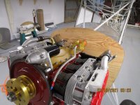
Hey Guys, It been awhile since I last posted, that doesn't mean I haven't been working. I am working on getting the engine compartment put together. I have a temporary plywood firewall installed presently and I am getting all the wires and oil lines and hoses sorted. I'm glad I did this because there were many things I thought would fit in certain places and when actually fitting them they didn't fit. I have a non-standard engine so you will see things on my engine you probably don't have on your standard airplane engine. Here are the pic, things look kind of sloppy now but nothing is permanent or fastened the way it will be when finished. hope you all like them.
Attachments
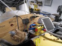


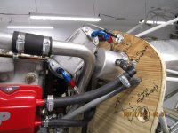
Hey Frank, Yes it is an oil cooler, it will be mounted in the rear baffle. Yes I do have a rib and spar kit from Mark. I got it a long time ago. I am in the process of gathering all the wing parts and aluminum to start the wings. I hope to get the fuse all done except covering in the next few months.
Hi Frank here ya go. I hope they are helpful.
Attachments


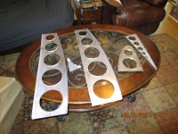


Frank
Well-known member
Many thanks Dave. Just as I suspected. Yep those are some superior ribs! I am jealous of the intact nose with the narrow flange which will support the leading edge. (As you know, the plans instruct us to trim the nose on the LSA ribs before riveting the skins.) Advanced hydroforming is what it is.
I'm curious though if the other models scratch builders do the same. Do they also trim their noses, so to speak, before riveting the skins?
And the joggle photos will definitely be useful. To joggle or not to joggle, that is the question!
Kudos to the factory!
I'm curious though if the other models scratch builders do the same. Do they also trim their noses, so to speak, before riveting the skins?
And the joggle photos will definitely be useful. To joggle or not to joggle, that is the question!
Kudos to the factory!
BTAZ
Well-known member
Per the plans, the front of the nose ribs aren't flanged so couldn't be fastened to the leading edge.
I don't think one would want them just pressing against the leading edge as they could fret. So once they have assisted positioning the leading edge and making sure it is in the proper curve, I believe they would need to come off before final skin installation.
And even if they are flanged all the way around the front, not sure one wants to drive skin-to-rib rivets any further forward than the plans show as driving them where the leading edge curves the most would distort it.
But Bob's view would be the answer.
I don't think one would want them just pressing against the leading edge as they could fret. So once they have assisted positioning the leading edge and making sure it is in the proper curve, I believe they would need to come off before final skin installation.
And even if they are flanged all the way around the front, not sure one wants to drive skin-to-rib rivets any further forward than the plans show as driving them where the leading edge curves the most would distort it.
But Bob's view would be the answer.
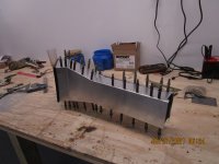
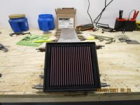
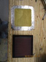
Hey guys after buying an expensive k&n air filter I mocked up an airbox today. The reason for the shape is because my carb sits very close to the firewall. I have not decided what to build it from. Aluminum or steel. I would like to hear what you guys have to say about it. Here are the pics of my mock up. This is old school solid works. Let me know what y'all think.
Attachments


Last edited:
interstate al
Junior Member
Love your version of solid works! Same release that I use!
I will probably fabricate my box out of sheet metal but will be watching the feedback you receive too.
I will probably fabricate my box out of sheet metal but will be watching the feedback you receive too.

JimParker256
Bearhawk Enthusiast
I use a wireless version of "Pencil-CAD" myself... LOL
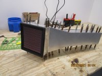
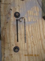
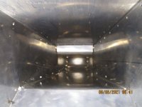
Hey guys worked on my air box today. fabricated it from aluminum, working on the flapper for the hot air in the air box. Bought a shaft with pivots with bushing. The store bought shaft did not have a flat edge to it. So I made another shaft milled a flat edge on it and drilled and tapped 6/32 holes to attach the flapper valve. Box is clecoed together now. I used my special cnc weiss aviation snips!!!
Attachments





interstate al
Junior Member
Looks great dave!
Hey Guys, I worked on the airbox again. I got the hot air flapper working. I got the carb connector on with brass screen between the connector and the airbox. I got the flange around the front of the airbox. Also got the escutcheon for the filter with brass screen in it and fitted the filter into the front of the airbox. Im waiting on the 2 inch flange to come in so it can be attached to the hot air hole in the top of the airbox. I also found a way to make a joggle by first bending an angle then backing one side of the angle to a 1/4 inch thick steel bar and clamping everything down to the table and beat one edge of the angle down on the steel bar.
Attachments





Last edited:
Hey Guys, I finally finished my airbox. I had no idea it was going to be such a big project. I didn't keep exact time on it but I know I had over 40 hours in it. It is not as pretty as Robs box but I'm not the craftsman he is. It is functional though. It has a removable filter and a heat control valve. It is now connected to the control lever in the cockpit and it is functioning.
Attachments
-
 photo9441.jpg2 MB · Views: 0
 -
 photo9442.jpg2 MB · Views: 0
 -
 photo9443.jpg2.1 MB · Views: 0
 -
 photo9445.jpg2.2 MB · Views: 0
 -
 photo9444.jpg2.1 MB · Views: 0
 -
 photo9446.jpg2 MB · Views: 0
 -
 photo9447.jpg2.2 MB · Views: 0
 -
 photo9448.jpg2.3 MB · Views: 0
 -
 photo9449.jpg2 MB · Views: 0
 -
 photo9450.jpg1.9 MB · Views: 0
 -
 photo9451.jpg2 MB · Views: 0
 -
 photo9452.jpg1.9 MB · Views: 0
 -
 photo9453.jpg2.1 MB · Views: 0
 -
 photo9454.jpg1.9 MB · Views: 0
 -
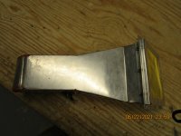 photo9455.jpg2 MB · Views: 0
Last edited:
Hey Guys, I have a question that is directed to built and flying LSA;s. Does anyone have an idea what the weight is of a completed seat front and rear weigh on the LSA? Im thinking of buying a ready built race car seats. I have found them with a low weight as low as 24lbs. I dont really like the looks or the expense of a "real" aircraft seat.
Hey Guys, I dont have any pic for today but I have been working on my LSA. I now have my fire wall all sorted and all my engine connections figured out. My next step will be to completely disassemble the fuse as it is and sand blast all the parts I have welded on and get it primed again and painted. At this point I will be at the fast build stage and can start to permanently began to assemble the fuse and then I can get started on my wings. I want to bring up a safety point as well. My good friend William Wynne was almost burned to death in an accident many years ago. The reason was rigid fuel lines that fractured in the accident. As a consequence he now recommends flexible fuel lines. I have thought about this a lot and it is more expensive than rigid lines but I think the safety factor out weights the cost consideration. And the cost is not that much more than rigid lines. Recently I was looking at some of the newest general aviation aircraft reviews and the Diamond DA62 and as far as I know all their other models are using flexible fuel lines. So if you have not yet installed your fuel system I offer this for your consideration. I believe it has the potential to save lives. Here are 2 products that will satisfy this safety requirement.
Earl's Performance 610006ERL - Earl's Performance Speed-Flex Hose
Earls 809106ERL 90 Degree -6 AN Female to -6 AN Hose Adapter
Earl's Performance 610006ERL - Earl's Performance Speed-Flex Hose
Earls 809106ERL 90 Degree -6 AN Female to -6 AN Hose Adapter
Last edited:

Before we consider changes to the designed fuel system, let's keep in mind that there are any number of ways to cause fuel leaks in a crash. There also many ways to cause a crash, including inadequately designed fuel systems. Bob's design is not arbitrary or without considerable experience and thought.
Hi Jared, I don't advocate changing Bobs' design, only replacing the rigid lines with flexible lines.
You are changing the design, perhaps without changing the general routing. The materials are an important part of the original design and are also not selected arbitrarily. I think you are likely to find that the flexible lines have a much larger minimum bend radius, which will impact routing, a much shorter shelf life, and perhaps other complications that are yet to be uncovered.
Can you pose an example where a flexible line will mitigate a risk that 5052 aluminum lines (which are also, to a degree, flexible) will not?
Hi Jared, I have found many examples where a flexible fuel line can mitigate the risk of a post crash fire. There have been studies of this and all of the examples I have found support this. Here is a large PDF document of a study put out by the FAA and the DOD. Here is an excerpt for that document. "4.2.6 Fuel Lines.Damaged fuel lines frequently cause spillage in aircraft accidents. Lines often are cut by surrounding structure or worn through by chaffing rough surfaces. The use of flexible rubber hose armored with a steel-braided harness is strongly suggested in areas of anticipated dragging or structural impingement. In systems where breakaway valves are not provided, these stretchable hoses should be 20 to 30 percent longer, before stretching, than the minimum required hose lengths. This will allow the hose to shift and displace with collapsing structure rather than be forced to carry high tensile loads. For this reason, it is equally important that couplings and fittings be used sparingly because of their propensity to snag and restrict the natural ability of the hose to shift." The document in its entirety can be found here : http://www.tc.faa.gov/its/worldpac/techrpt/ar01-76.pdf, I believe the most vulnerable area of the fuel lines in a crash is where the lines connect to the tanks at the wing roots. But anywhere in the system exposed to other crash forces would benefit of a more flexible line. But as has been said this is an experimental airplane and we are free to build anyway we see fit. Here in another document put out by the FAA and DOD that also seems to support this conclusion. https://ntrs.nasa.gov/api/citations/20030033927/downloads/20030033927.pdf, Everyone must make up their own minds how they want to proceed. I am just offering information for ones consideration.
The idea is that in a crash, the parts will be able to move without separating the lines? This seems like a very narrow window, where there is more movement than the 5052 lines can provide, but less movement than will still rip out the flex lines.
Im my friends case it was a Pietenpol aircraft ; when the nose hit the ground the wings shifted forward and the rigid fuel line connections to the fuel tanks at the wing roots broke and covered him with fuel. I was just thinking that our Bearhawks are high wing like the Peitenpol and could possibly experience a similar failure in a crash. So yes the main idea is that the lines can move as opposed to breaking. The line slipping out of the fitting is not usually seen in these systems if properly built. As with most systems we use it is recommended that one would stay with the same manufacturer for all the fitting and lines through out the system. As you know in a very rigid system movement of any kind, even vibration can cause fatigue fractures and then very little movement can cause a complete failure. This is where the flexible lines can be used to mitigate much of this possibility. I don't think any system will keep a turn to base and stall and spin in would do much to save anyone. I believe the flex lines and self sealing frangible couplings are just one tool we can use to make flying a little safer. And it is something worth considering.
Last edited:
Mark Goldberg
Bearhawk Aircraft
Dave, most builders use a small length of rubber line between the wings and the fuselage. For the example of what happened to Will - that might have sufficed if in fact the rubber line would not break loose like a rigid line. If there was enough movement, it would seem like the lines would come loose no matter what they were made of. Mark

Bcone1381
Finished Patrol
The context of my comment #304.1, regards Flex Fuel hose only in the Firewall Forward area to accommodate vibration and engine movement without fatiguing a rigid fuel line.. Posts after this indicates that I made an error, and the context rather was regarding the entire airframe.
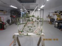
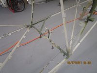
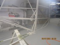
Hi Guys,I have a little more progress to report. I have finally finished all the welding Im going to do to my fuse. I have one more set of fair leads I need to weld in then I will sand blast and do a final paint job before final assembly.Also I have built one of the most useful things you can have in your shop. How many times have you been wrenching on your airplane and you have a ratchet in one hand and a wrench in the other, and you needed somewhere to lay the nut and bolt until you could get it installed? It's kind of like a third hand. Not only that it also can be your beer assistant. Hope you like the pics.
Attachments




Gerhard Rieger
Well-known member
Good progress
OK fellas, I am in the middle of sand blasting my fuse again where I have done some welding. It has been difficult, its 9000 degrees outside and 200 percent humidity out there so it is slow going. This is the last step before the FINAL assembly can begin. I also have parts that need sand blasting so more fun on the way. Once I get it all nice and sand blasted and painted and pretty Ill have more pics.


California has the nice weather, but enough other folks have figured that out to make it undesirable for me.

Hi Fellas, I have a little more progress to report today, I spent all day today sand blasting my fuse and control system parts. Tomorrow Im planning on cleaning and hopefully start painting again. Im going to shoot it with several coats of primer and a top coat. pic to come soon.

Hey Frank, I use crushed glass and a sandblasting rig from horrible freight. I find that it does a better job cleaning the metal and it can clean spots you cant get to with a wire wheel, I do use the wire wheel too, it is good for removing carbon after welding. Its a lot of hot sweaty work but the end result is worth it. you also need a good air compressor, Mine has a 60 gallon tank with a 220vac motor. ill post pics when im done.
Last edited:
I found that blasting got the funky stuff out of the nooks and crannies around the weld beads. I couldn't get it clean there with any other methods that I tried. One option is to rent a big 100cfm compressor from the local tool rental place and do it all in one day. Just pick a day that isn't hot!