You are using an out of date browser. It may not display this or other websites correctly.
You should upgrade or use an alternative browser.
You should upgrade or use an alternative browser.
Kit #7 arrived
- Thread starter Utah-Jay
- Start date

Utah-Jay
BH Companion
It was the day to remove the engine cowl and nose bowl. Lots of filling and sanding, then rinse and repeat several times
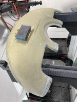
The I printed on the pinhole filler, so lots more sanding to come. This pinhole filler sands really easily though.
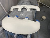
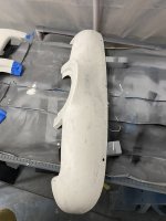
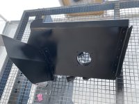
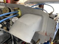
The last phase of the airflow for the air filter was this fiberglass bracket which will have a metal strip for the riveting process. Laying up fiberglass is getting easy, which is good with the window faring still to come.

The I printed on the pinhole filler, so lots more sanding to come. This pinhole filler sands really easily though.
The last phase of the airflow for the air filter was this fiberglass bracket which will have a metal strip for the riveting process. Laying up fiberglass is getting easy, which is good with the window faring still to come.
Utah-Jay
BH Companion
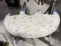
This is what 5 1/2 hours of sanding looks like after yesterday's application of the pinhole filler. The blue spots are superfill in a few areas that needed filling
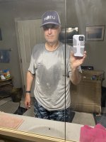
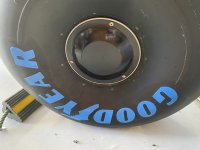
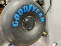
This is what 2 hours of changing out tires looks like in a dry climate. I have no clue how you guys live in humidity
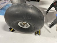 I sold the 26” ABW back to the original owner, luckily he wasn’t them to run during the winter months. I figured the GY’s will be a lot more durable for all the phase 1 flights and I figure I will get in the air during the winter when our grass is covered with snow.
This is what 2 hours of changing out tires looks like in a dry climate. I have no clue how you guys live in humidity
I sold the 26” ABW back to the original owner, luckily he wasn’t them to run during the winter months. I figured the GY’s will be a lot more durable for all the phase 1 flights and I figure I will get in the air during the winter when our grass is covered with snow.

Utah-Jay
BH Companion
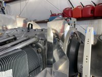
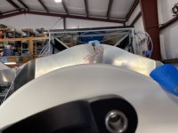
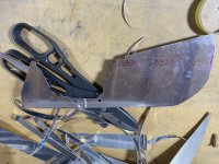
It was a baffling day, lots of measuring and them more measuring, then cutting. I was sneaking up on what I wanted, so I probably averaged over 2 cut/trims per piece. Several took 3 or 4
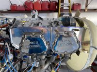
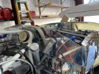
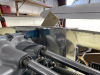
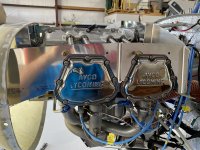
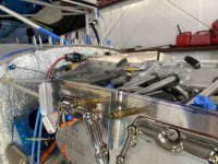
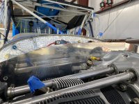
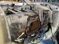
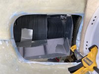
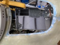
This is the end of the day baffling scrap pile
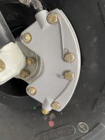
I had been monitoring my new GY 26’s for tire pressure, especially after one had a bad valve that I replaced. After 3 days holding pressure I put on the hob caps and re-installed the brake pads which is not one of my favorite activities. All safety wired up too.

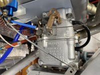
Yesterday I finally cut the pass through for the carb heat and ran the cable. I reattached the Throttle and Mixture. I had to build a stand-off for the Carb Heat cable and then cut the cable to length and attach.
This is the end of the day baffling scrap pile
I had been monitoring my new GY 26’s for tire pressure, especially after one had a bad valve that I replaced. After 3 days holding pressure I put on the hob caps and re-installed the brake pads which is not one of my favorite activities. All safety wired up too.
Yesterday I finally cut the pass through for the carb heat and ran the cable. I reattached the Throttle and Mixture. I had to build a stand-off for the Carb Heat cable and then cut the cable to length and attach.

spinningwrench
Patrol
Normally the bolts on the carb float
bowl are either safety wired
or use the special no spin lock washers.
bowl are either safety wired
or use the special no spin lock washers.
Utah-Jay
BH Companion
Because TrueAirSpeed gave me grief about not posting lately…
Yes, I have been chipping away at the baffling, as well as priming for painting. I did try painting the spinner, but the environment was just not sterile enough to get the results I was shooting for. I found a new place to paint.
Hmmm, baffling. I will say this is the first time during the build that I actually felt defeated. It was just kicking my ass! Made progress today. Did a lot of match drilling and made progress for what seems like the first time in a week. It was a rarity, but I was so defeated I actually took a day and went fishing to get a break.
Here is my progress
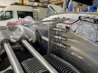
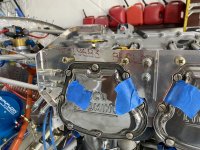
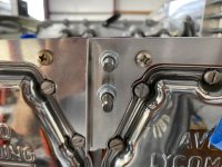
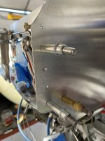
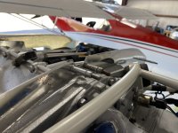
Had some interesting visitors yesterday
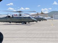
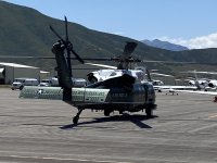
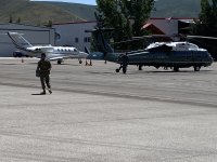
Marine 1 and 2
Yes, I have been chipping away at the baffling, as well as priming for painting. I did try painting the spinner, but the environment was just not sterile enough to get the results I was shooting for. I found a new place to paint.
Hmmm, baffling. I will say this is the first time during the build that I actually felt defeated. It was just kicking my ass! Made progress today. Did a lot of match drilling and made progress for what seems like the first time in a week. It was a rarity, but I was so defeated I actually took a day and went fishing to get a break.
Here is my progress
Had some interesting visitors yesterday
Marine 1 and 2

TrueAirSpeed
Junior Member
Hang in there Jay! You’re doing fine.
Utah-Jay
BH Companion
If anyone ever says baffling is fun I might hit them with a shovel 
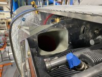
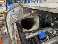
This is super slow and tedious, I am just measuring about 20 times, then a few more then times for good measure (pun intended) I finally started drilling and putting things together today.
Front ramp/ram air area
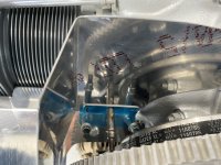
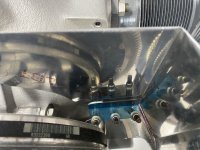
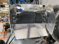
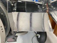
This is super slow and tedious, I am just measuring about 20 times, then a few more then times for good measure (pun intended) I finally started drilling and putting things together today.
Front ramp/ram air area


rodsmith
Well-known member
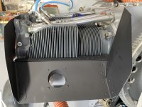
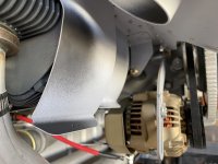
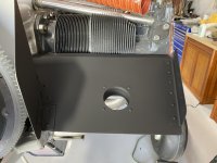
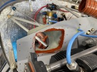
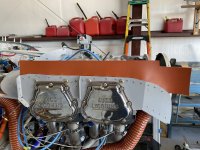
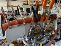
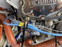
I feel your pain. The baffling work has turned into the most frustrating time consuming part of the project. Currently shaping foam for carbon transition pieces from the front of the aluminum baffling to the cowl inlets. I have a 3" prop extension which complicates the process further.
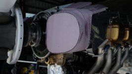
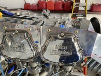
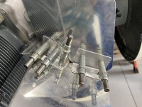



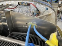
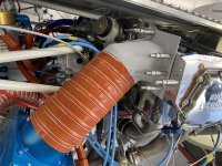
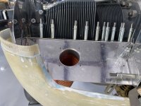


Hang in there Jay, I remember also having weeks in the baffling.


Utah-Jay
BH Companion
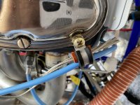
Of course there was more more on the engine cooling
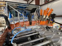
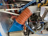
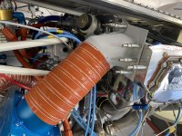
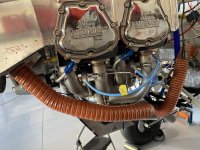
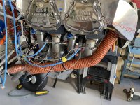
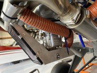
I wrapped a cabin heat scat tube with anti-chaff tape in case there is any
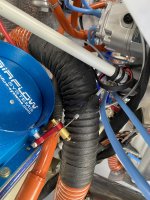
Wrapped the front end of the same cabin heat system with Kevlar heat shield as it is close to the exhaust. I also put a double standoff to keep the scat tube from making contact with the exhaust
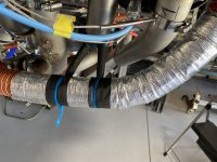
I wrapped a cabin heat scat tube with anti-chaff tape in case there is any
Wrapped the front end of the same cabin heat system with Kevlar heat shield as it is close to the exhaust. I also put a double standoff to keep the scat tube from making contact with the exhaust
Utah-Jay
BH Companion
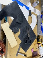
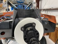
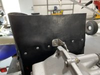
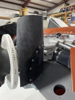
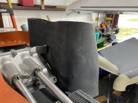
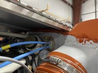
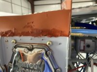
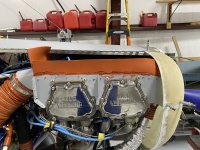
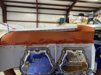
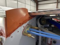
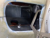
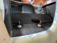
Installed nearly the last of the silicon sheets for the cooling, I have the under the front ramp to do, but that is super ease. I actually doubled up the “thin” black stuff that cam with the Vans kit so it would be stiffer. I just did not want the red/orange visible below the front ramps
Tomorrow starts the trimming
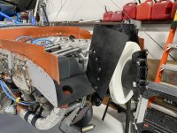
Tomorrow starts the trimming
Attachments

Utah-Jay
BH Companion
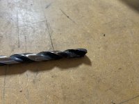
How do you ruin a perfectly good 5/16ths drill bit? Use it to upsize the stinger tailwheel spring.
But it is all done and installed with a close tolerance AN175-15 bolt
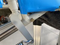
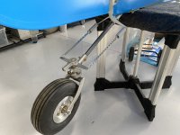
After drilling it out, both the spring and the mounting hole, both were reamed. Note: pull the reamer through
But it is all done and installed with a close tolerance AN175-15 bolt
After drilling it out, both the spring and the mounting hole, both were reamed. Note: pull the reamer through
Last edited:
Utah-Jay
BH Companion
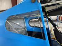
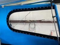
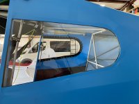
Rear windows went in today for the last time. I used Butyl sealant tape to seal against water leaks. As you can see form the photos there is a bit of putty removal needed, but I want to give it a few days to really settle in before I remove the excess.
Attachments

Utah-Jay
BH Companion
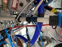
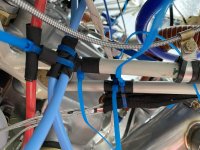
Over the past few days I have been securing lines and hoses in the FWF area using high temperature zip ties and silicon tubing to create standoffs so there is no rubbing or chaffing.
Attachments
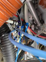
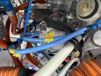
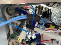
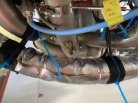
Utah-Jay
BH Companion
rodsmith
Here ya go:
https://www.cabletiesandmore.com/tefzel-cable-ties
I got the 11.6” 50 pound ones.
Here ya go:
https://www.cabletiesandmore.com/tefzel-cable-ties
I got the 11.6” 50 pound ones.
Utah-Jay
BH Companion
Engine cowl final fit and holes upsized for #8 screws and nutplates as well as #4 rivets
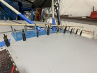
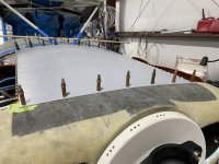
 Black clecos are for #8 screws, copper colored clecos are for #4 rivets. The Cowl top will be riveted to the top of the nosebowl and the cowl bottom will be riveted to the bottom cowl.
The nosebowl and engine cowl will not be painted until after phase 1. Boot cowl will be pained and riveted in “soon”
Black clecos are for #8 screws, copper colored clecos are for #4 rivets. The Cowl top will be riveted to the top of the nosebowl and the cowl bottom will be riveted to the bottom cowl.The nosebowl and engine cowl will not be painted until after phase 1. Boot cowl will be pained and riveted in “soon”
Utah-Jay
BH Companion
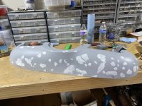
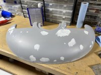
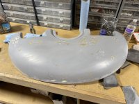
It was like Groundhog Day only in hours. I am on my 7th time of filling, sanding and priming. Looks like bottom cowl is now at an acceptable level to get it through Phase 1, which after Phase 1 I will paint the engine cowl. I am only chasing pinholes. I may also add fiberglass reinforcement to the inside of the bowl
Utah-Jay
BH Companion
Somebody took my plane apart
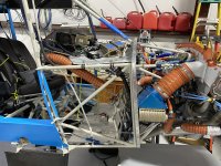
Kidding aside, I am preparing for painting the boot cowl. Both the boot cowl and the firewall are dimpled for flush rivets. Now it is prep for painting time.
I took the opportunity to finally trouble shoot my faulty Carb Heat sensor issue, I had a bad splice leading to the D-Sub, so redid that, this time I checked it on the ohm meter to make sure all was good.
Kidding aside, I am preparing for painting the boot cowl. Both the boot cowl and the firewall are dimpled for flush rivets. Now it is prep for painting time.
I took the opportunity to finally trouble shoot my faulty Carb Heat sensor issue, I had a bad splice leading to the D-Sub, so redid that, this time I checked it on the ohm meter to make sure all was good.
Utah-Jay
BH Companion
Well, today was a visual day.
It was a serious milestone! I filled and sanded the nosebowl about 30 times, all be it at the end with 400 and 600 grit sandpaper. How long does a cycle of filling and sanding take? About 4 hours each time. It was like chasing a GHOST! But today it was all worth it
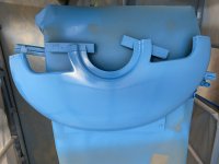
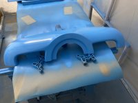
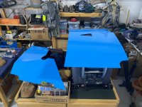
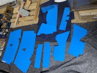

 Tomorrow the engine cowl gets riveted to the nose bowl and will all be painted.
Happy Days
It was a serious milestone! I filled and sanded the nosebowl about 30 times, all be it at the end with 400 and 600 grit sandpaper. How long does a cycle of filling and sanding take? About 4 hours each time. It was like chasing a GHOST! But today it was all worth it
Tomorrow the engine cowl gets riveted to the nose bowl and will all be painted. Happy Days
Utah-Jay
BH Companion
Just to add, yes the paint has a texture, it is by design to match my Oratex fabric
The photos of the nosebowl were taken inside the paint booth so the lighting was great for the photos, but the nosebowl looks great. Sadly it gets sanded tomorrow morning, then riveted and painted again after riveting to the respective top and bottom engine cowl
The photos of the nosebowl were taken inside the paint booth so the lighting was great for the photos, but the nosebowl looks great. Sadly it gets sanded tomorrow morning, then riveted and painted again after riveting to the respective top and bottom engine cowl
Last edited:
Utah-Jay
BH Companion
After spending 11 of the past 14 weeks working overseas, it is good to be back and working on the plane.
Yesterday I hooked up lights to all the wing wires to confirm everything is working, only had one hiccup and that was an easy fix once the problem was diagnosed. So wing wires are all set.
Today I fastened up all the wiring behind the panel so it is a bit more tidy looking.
I also riveted the top and bottom engine cowls to the nose bowl so I can paint them.

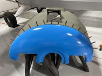
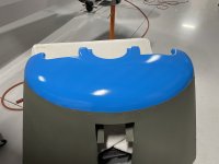
You may notice the texture in my paint, it is on purpose to match the texture of my oratex fabric
Yesterday I hooked up lights to all the wing wires to confirm everything is working, only had one hiccup and that was an easy fix once the problem was diagnosed. So wing wires are all set.
Today I fastened up all the wiring behind the panel so it is a bit more tidy looking.
I also riveted the top and bottom engine cowls to the nose bowl so I can paint them.
You may notice the texture in my paint, it is on purpose to match the texture of my oratex fabric
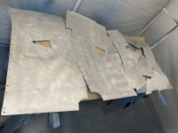
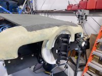
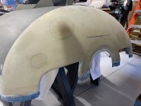
How did you know there was a problem, did it not fully set up? I know that repeating work can be frustrating, but it is much easier to fix now than later.
Utah-Jay
BH Companion
How did you know there was a problem, did it not fully set up? I know that repeating work can be frustrating, but it is much easier to fix now than later.
Jared
7 weeks ago when I painted I realized the paint was not drying as fast as it should on the first 2 batches of mixture. That is when I checked the labels and realized I used the epoxy primer actuator rather than the paint actuator. I figured with a 5 week work trip in the days following it would be fully cured when I got back. But sadly there were still a few tacky spots. So I figured I would not take any chances and strip it all and start over. It was tedious and messy, but the right thing to do
Utah-Jay
BH Companion
Lot of work has been done, not many photos… But here is some progress
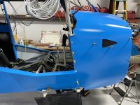
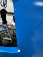
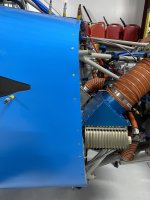
All of the boot cowl extension, or behind the front door frame is riveted in. I used stainless pull rivets.
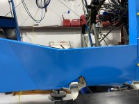
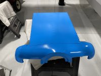
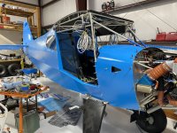
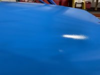
I guess some people call it orange peel, but I painted all the surfaces with a matte type finish to match my oratex fabric
I would have finished all the riveting, but I needed CCP-32 rivets for the front of the tunnel rather than -34 as the -34 were just a tad bit too long and contacted the bottom tubing where the firewall attaches.
Spinner should be painted black tomorrow.
Floorboards are in place and just need to be secured.
Too much other stuff to remember.
All of the boot cowl extension, or behind the front door frame is riveted in. I used stainless pull rivets.
I guess some people call it orange peel, but I painted all the surfaces with a matte type finish to match my oratex fabric
I would have finished all the riveting, but I needed CCP-32 rivets for the front of the tunnel rather than -34 as the -34 were just a tad bit too long and contacted the bottom tubing where the firewall attaches.
Spinner should be painted black tomorrow.
Floorboards are in place and just need to be secured.
Too much other stuff to remember.
Utah-Jay
BH Companion
Boot cowl is riveted in, Naca’s are riveted in but not plumbed yet as I wanted the silicon to get a chance to completely dry/cure. The gray “box” on top is removeable to get to avionics if needed and will be under the “carpet” on the glare shield. I had ONE FREAKING rivet that gave me trouble and had to drill it out 3 times to get it right.
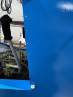
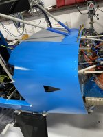
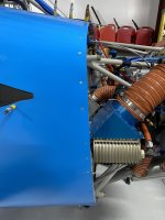
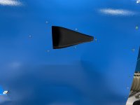
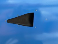 I used butyl tape between the firewall flange and the boot cowl to eliminate any chance of CO gas from coming into the cabin via a leak. I also used silicon on the firewall/tunnel junction to also stop CO from sneaking into the cabin.

I used butyl tape between the firewall flange and the boot cowl to eliminate any chance of CO gas from coming into the cabin via a leak. I also used silicon on the firewall/tunnel junction to also stop CO from sneaking into the cabin.
Utah-Jay
BH Companion
Made the gasket for the gear struts (sorry forget to take a photo)
Screwed in the front floorboards for the last time
Put torque seal all the nuts that need inspecting for preflight and annual condition inspection
Set the auto-pilot servo arms with the stick in the neutral position both fore/aft and left right
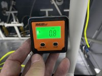
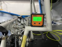
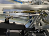
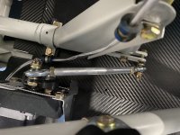
I have the servo limiting brackets on both the roll and pitch servos, so I set the servo in the middle and adjusted the arms for the neutral stick position. The roll servo arm is not cotter pinned as there is a slight chance it might need to be adjusted once the wings are on and the ailerons are rigged.
Air vents are plumbed
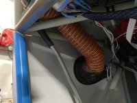
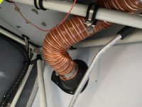
As far as I can tell the only things needed to be done on the fuselage are to mount the prop blades (tomorrow) and bleed the brake lines later this week.
I built wing cradles this week and they are all secure on stands.
Let the wing fun begin.
For the record I started building on October 1st, 2021. I travel for work in blocks of weeks from 2-6 weeks at a time totaling 22-24 weeks a year. I have taken less than 10 days off when I have been home during the whole build process. Many times in the winter I only get to the hanger about 2pm as we ski most mornings (make sure you keep your spouse happy during the build). Why am I stating this? To give folks an idea of build time. I was a COMPLETE neophyte when I started my build, I was totally delusional on the time it would take to complete. I hope this might help someone on the fence. Building a plane is not hard, but can be frustrating, stick to it and you can do it.
Screwed in the front floorboards for the last time
Put torque seal all the nuts that need inspecting for preflight and annual condition inspection
Set the auto-pilot servo arms with the stick in the neutral position both fore/aft and left right
I have the servo limiting brackets on both the roll and pitch servos, so I set the servo in the middle and adjusted the arms for the neutral stick position. The roll servo arm is not cotter pinned as there is a slight chance it might need to be adjusted once the wings are on and the ailerons are rigged.
Air vents are plumbed
As far as I can tell the only things needed to be done on the fuselage are to mount the prop blades (tomorrow) and bleed the brake lines later this week.
I built wing cradles this week and they are all secure on stands.
Let the wing fun begin.
For the record I started building on October 1st, 2021. I travel for work in blocks of weeks from 2-6 weeks at a time totaling 22-24 weeks a year. I have taken less than 10 days off when I have been home during the whole build process. Many times in the winter I only get to the hanger about 2pm as we ski most mornings (make sure you keep your spouse happy during the build). Why am I stating this? To give folks an idea of build time. I was a COMPLETE neophyte when I started my build, I was totally delusional on the time it would take to complete. I hope this might help someone on the fence. Building a plane is not hard, but can be frustrating, stick to it and you can do it.

Utah-Jay
BH Companion
82’ Sensenich GA STOL prop is now on set to the #5 pitch. Prop is just a smidge over 15” from the floor when the plane is in a level attitude with GY 26” (really 24”) tires. I don’t see myself ever using smaller tires, which if smaller the prop could become too close to the ground for my liking.
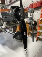
Cargo floor has been covered with the carbon fiber wrap and is installed and nearly all bolted in.
Spent a good part of the day cleaning up fuselage “stuff” and prepping for the wing work to begin.
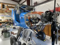
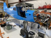
Cargo floor has been covered with the carbon fiber wrap and is installed and nearly all bolted in.
Spent a good part of the day cleaning up fuselage “stuff” and prepping for the wing work to begin.
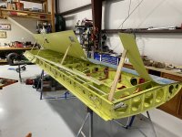

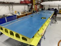
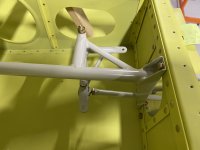
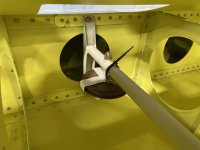
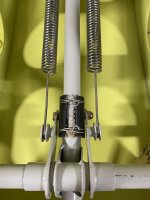
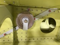

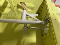
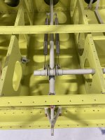
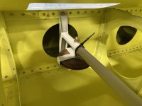
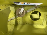
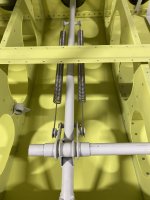

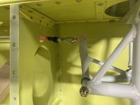
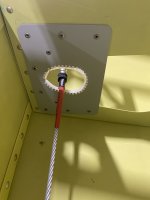
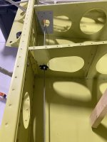
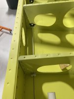

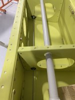

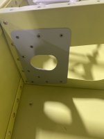
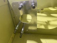
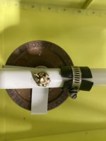

Don't forget the cotter pin on your bellcrank bolt. Also, when you locate your turnbuckle in the cabin for the crossover cable, offset it as far as you can to one side, as to minimize the interference with the elevator trim cable.
Utah-Jay
BH Companion
Don't forget the cotter pin on your bellcrank bolt. Also, when you locate your turnbuckle in the cabin for the crossover cable, offset it as far as you can to one side, as to minimize the interference with the elevator trim cable.
Jared, that cotter pin is not there as I am replacing the fork, but thanks.
I am planning on offsetting to the right/co-pilot side

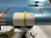
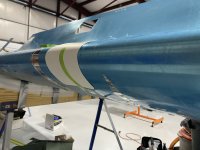
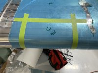
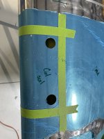
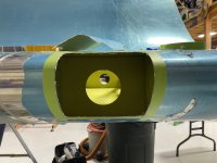
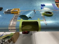
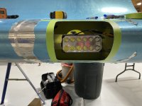
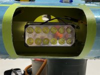
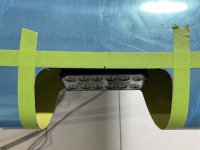
Utah-Jay
BH Companion
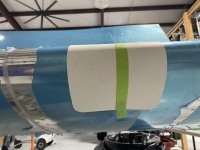
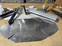
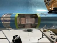
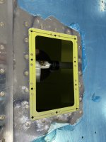
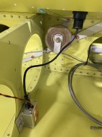
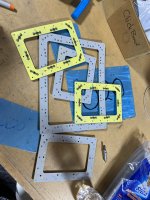
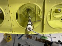
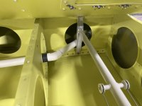
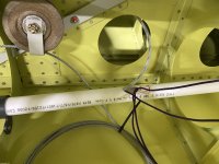
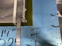
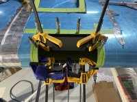
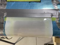
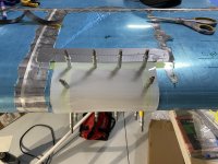
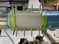
Nice! What tool did you cut it with and are you adding a doubler?
I used a step drill for my corner radius and then a new dremel saw (disk) blade. Putting the tape down and cutting inside the tape line made it a lot easier.
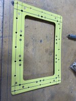
My lens will have a backing for the nut plates/anchor nuts.
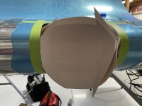
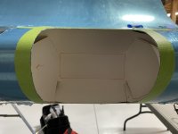
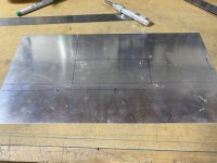






Utah-Jay
BH Companion
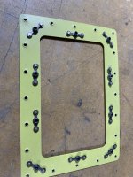
After all the holes were match drilled, they were upsized for the #6 screws
Next was installing the nut plates in the backing plate followed by using click bond to install it.
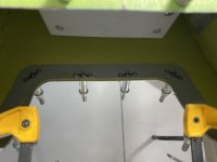
Drilled the hole for the fuel tank Curtis drain, it was off by about 1/64th” so a bit of sand paper on one side made for a good fit.

Next was installing the nut plates in the backing plate followed by using click bond to install it.
Drilled the hole for the fuel tank Curtis drain, it was off by about 1/64th” so a bit of sand paper on one side made for a good fit.

kestrel
Offering Bearhawk rides
What is the power supply that you chose? How was it chosen?Camera power installed with a panel switch
Thanks!
Utah-Jay
BH Companion
What is the power supply that you chose? How was it chosen?
Thanks!
kestrel
I did a ton of research as I disliked batteries running out. The product I am using used to be FlightFlix, but FlightFlix was sold. The original owner kept the technology and he is GREAT to deal with.
I wired my panel with a “Camera” rocker switch so I can control things. I don’t want to post Ryan’s phone number online, but if interested PM me and I will send it to you.
Super easy to wire, and weighs next to nothing.
Jay T

Utah-Jay
BH Companion
At some point between the age of 5 and 61 years old pulling plastic off metal ceased to be fun
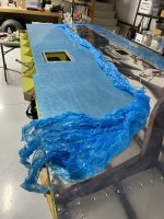
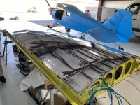
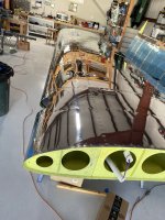
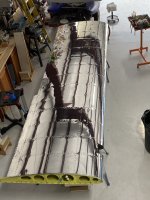
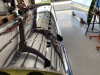
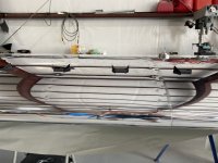
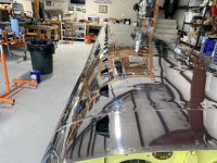
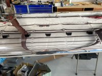
The main wing skin is no riveted, I left the trailing edge for the time being as I need to put in the stiffener and and playing with the idea of a coat of paint on it prior to riveting.
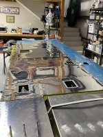
Fuel tank is in place (temporarily again), the rib is marked to drill holes for the fuel lines. Sadly I have a backordered 45 degree fitting and can’t finish this until it arrives.
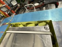

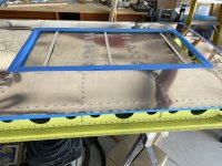
The cleco’ed panel below the bull tank will be riveted tomorrow in the two middle ribs initially.
The main wing skin is no riveted, I left the trailing edge for the time being as I need to put in the stiffener and and playing with the idea of a coat of paint on it prior to riveting.
Fuel tank is in place (temporarily again), the rib is marked to drill holes for the fuel lines. Sadly I have a backordered 45 degree fitting and can’t finish this until it arrives.
The cleco’ed panel below the bull tank will be riveted tomorrow in the two middle ribs initially.
Utah-Jay
BH Companion
Did the rough sanding on the wing tip light mount
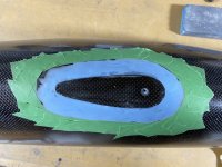
I added more SuperFill and will sand it to the final shape tomorrow.
Finished the wing light and it is all installed
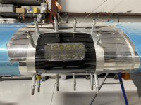
Started messing with fuel tank to fuselage line measurements. Thanks to Joe Mason I got the AN823-6D (they are non-existent at the moment) and need to drill one more hole for the fuel lines
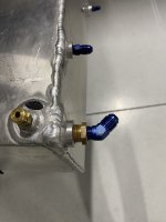
Yes the fuel tank is in the wing…. AGAIN…. But will be taken out…. AGAIN…. Once the correct hole locations have been marked for this last fitting.
I added more SuperFill and will sand it to the final shape tomorrow.
Finished the wing light and it is all installed
Started messing with fuel tank to fuselage line measurements. Thanks to Joe Mason I got the AN823-6D (they are non-existent at the moment) and need to drill one more hole for the fuel lines
Yes the fuel tank is in the wing…. AGAIN…. But will be taken out…. AGAIN…. Once the correct hole locations have been marked for this last fitting.

Utah-Jay
BH Companion
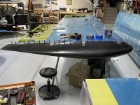
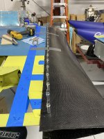
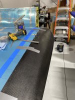
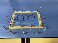
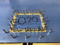
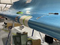
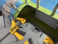
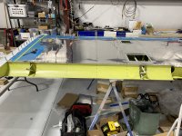
Poster failure, but I used would to create a wingtip trailing edge closeout and did not take a photo of the wood. The wood was shaped to the extended rib and out to the trailing edge of the aileron. I used Hysol epoxy to put it in place then clamped it as you can see in the photo


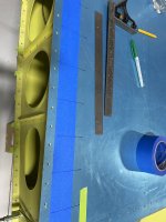
The trailing edge of the wingtip will be the inside edge of the green tape. The wood is in the space between the two green tapes.
The trailing edge of the wingtip will be the inside edge of the green tape. The wood is in the space between the two green tapes.

Utah-Jay
BH Companion
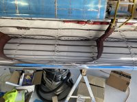
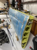
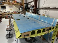
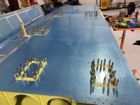
With the 2nd wing really just a repeat of the first I have not been posting much. All the wiring conduit is installed (same configuration as the first wing), camera power box is installed. Inspection covers are all match drilled, next stage is to drill for the nut plates.
I did F-up an inspection cover yesterday trying to install the pitot mount. NO clue how things went sideways as I measure about 10 times, and then it went to SH!T! Oh well.
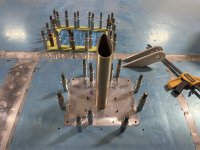
So today I made a new cover and cut in the mast mount. I am VERY proud of this. It is a better fit than the one that came with the kit.
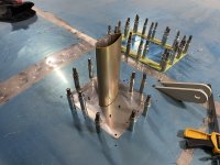
Wing #2 is going well, but off to work for 2 weeks tomorrow.
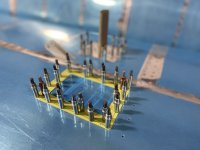
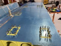
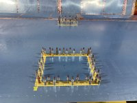
I did F-up an inspection cover yesterday trying to install the pitot mount. NO clue how things went sideways as I measure about 10 times, and then it went to SH!T! Oh well.
So today I made a new cover and cut in the mast mount. I am VERY proud of this. It is a better fit than the one that came with the kit.
Wing #2 is going well, but off to work for 2 weeks tomorrow.
Attachments
Utah-Jay
BH Companion
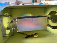
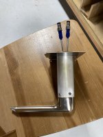
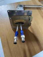
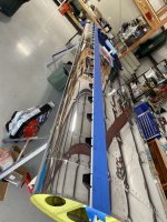
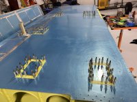
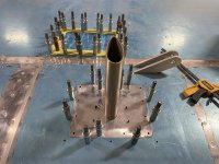
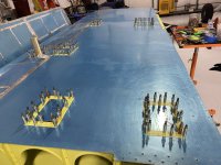
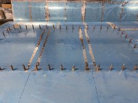
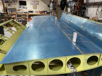
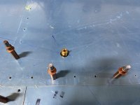
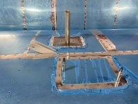
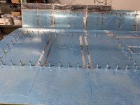
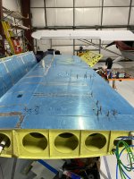
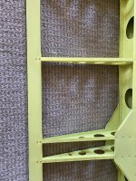
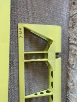
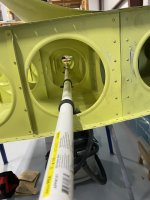
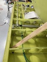
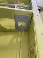
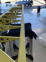
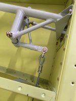
Lots has been happening, all the inspection cover backing plates have been installed, pitot tube mast is all riveted into an inspection cover. Pitot plumbing is done. Gas tank Curtis drain hole is cut and fits. I am sure I have missed some stuff in this update, but things are moving fast on the left (2nd) wing
Utah-Jay
BH Companion
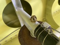
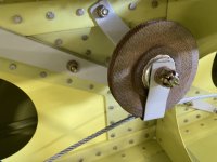
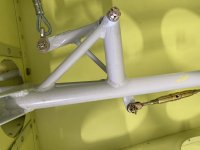
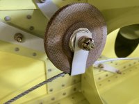
Left wing pulleys now have cotter pins and ready to go
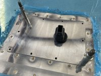
Left wing camera power is installed
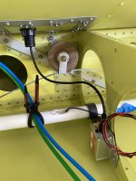
Did all the measurements for left wingtip drilling yesterday, wingtip will be drilled today.
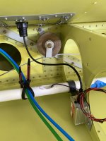
Charlie is in the hanger ready for wings to be hung when I get back from my next trip

Left wing camera power is installed
Did all the measurements for left wingtip drilling yesterday, wingtip will be drilled today.
Charlie is in the hanger ready for wings to be hung when I get back from my next trip