Nutplates and inspection panels

Bradrock

Well-known member
Nut plates have received some attention on this and other forums. I understand that k1100-06 are dimpled for flush screws such as on the inspection panels.

I see Eric used K1000 nutplates - what does one do about the dimples on the backside if using K1000's? (I have 500 of them!). Is it ok for the nutplates legs to sit on top of the dimples or do they have to be flush? It looks a little messy when riveted on top of the dimples but my understanding is that the nutplate merely needs to be held in place so that the screws will align.

Some direction here would be appreciated.
 
Short answer - you are good. I used the K1000 too, for the whole plane (dimpled or not), apart from a few one-armed nutplates here and there.

If you have a dimple die set for your rivet squeezer, and a countersinking reamer, then you are set. It was easy.

You can dimple the rivet holes of the nutplate, for flush riveted ones like the wing inspection ports and tanks, or you can put a straight K1000 over a dimpled set of holes. Both work out fine.
For the main threaded receptacle of the K1000, you can ream the opening a little to allow it to sit lower on a dimpled hole, per the Bearhawk Manuals. Just don't over do it, or you might weaken the nutplate. Again you can also ignore the dimple under the main receptacle and just use a straight nutplate. But that is a little untidier and probably slightly weaker, because the larger diameter dimple creates a larger stand-off. I would relieve the main receptacle to allow the nutplate to sit flush, in structural applications like the wing covers.
 
I had to grind a little off the female 3/32 die to clear the threaded section of the nutplate, but they dimple just fine.
 
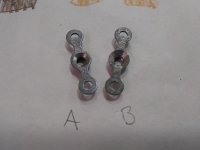
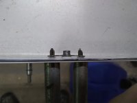
How much material have folks removed when countersinking k1000-6 nutplates? I feel like I'm removing too much material to get the nutplates legs to sit down on their dimpled holes. In the photo, the small countersinking on nutplate A does not allow the legs to touch as shown in the second photo. The large countersink on B allows it but I removed nearly half the threads to get there. Thanks in advance.

- Nic

1546949904359853626437.jpgIMG_20190105_054229465.jpg
 
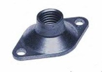
If the screw hole was dimpled, I always used the countersink version of the nutplate (k1100 or MS21049). Click image for larger version  Name:	military-standard-ms21049-series-two-lug-low-height-100-176-countersunk-nutplate-4.jpg Views:	1 Size:	6.0 KB ID:	43285
If the screw hole was countersunk in the substrate, then I would use the k1000 as pictured.
 
Last edited:
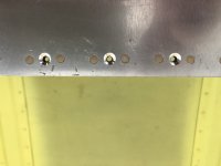
I haven't countersunk any #6 nutplates, they just sit on top of the 3 dimples like in your photo.

I find getting them to sit down flush is a pain, so I cleco both rivet holes and put in a screw to hold everything tight in place, then rivet. Seems to work well that way.
 
Last edited:
It's a bit hard to see, but in the photo there is a gap between the legs of the nutplate and the top of the dimples. You're saying that's ok?
 
It's a bit hard to see, but in the photo there is a gap between the legs of the nutplate and the top of the dimples. You're saying that's ok?

Prior to riveting I see a tiny gap like you notice, after everything cinches up nicely save for one or two nutplates I may or may not replace. These only need to keep the nutplate from rotating really. If you get a good shop head I wouldn't worry if it's stood off a couple thou...

Take some scrap and do some test nutplates to see if it's acceptable to you, that's what I did.
 
Last edited:
FWIW: I have found it very helpful to run a 6-32 tap into each nutplate after installation...greatly reduces the number of sheared-off screws that have to be drilled out. Also, using anodized instead of stainless screws seems to help.
 
With most sincere respect to Ray I quite strongly disagree about running a tap through a nutplate. Doing so eliminates the self-locking feature of the crimped body and, strictly speaking, destroys your standard mil-spec hardware (though countersinking effectively does this as well).

Installing, removing, and re-installing in excess of several hundred or so #6 screws now I've had exactly 1 head snap off and that was my cross threading to begin with. One thing I don't like about the spec'd MS screws is how mangled the phillips head gets, so my ACS cart has a couple hundred NAS514s in queue. I would recommend that before trying to alter standard hardware.
 
Ray, I run a tap into the nutplates as well. Of course a little common sense is helpful here...you don't want to take away too much of the locking feature. I just run the tap in about half way or so. This is a tip I learned a long time ago from the RV guys. It sure makes the screws easier to install and remove! And yes, I even use a lot of stainless steel screws...I know.. the galling thing. Put a tiny drop of fuel lube in each nutplate. "Different strokes" as they say...
 
Speaking of the locking feature on the screws... On the plans, Bob recommends using #6 screws (also aluminum pop rivets) for attaching the sheet metal to the doors and window frames. They are tapped into the 4130 tubing. Just good-n-tite...no locking feature! Could use loct-tite on the screws maybe. That works OK, I suppose and is what I have always done,

But what got me to thinking was Bob recommends using a similiar method to attach the skylite. #6 screws tapped into the 3/8" square tube formers at the wing root fairing. On the skylite attach, I have always felt that the screws should be slightly loose to allow expansion and contraction of the lexan. A big piece of glass like that REALLY does move. I tried putting some loct-tite on the screws that attach the glass on my first Beahawk build, and the glass didn't like that at all! Little star like cracks developed around each screw hole, lexan is not resistant to the lock-tite apparently. So I asked Bob what he did to provide some "locking feature" for the screws. He said when tapping for the screws, to run the tap only partially in, just when you feel it "break through". That way the screws will be tight and provide a locking feature.

Bob also told me he uses aluminum pop rivets to attach the glass in the windows. He doesn't pull them completely to break the stem, just enough to expand the rivet slightly and then cuts the mandrel off flush, touching it up a little with a file or dremel tool. That way the glass is not held too tight and is not crushed even though there is an aluminum back up strip.
 
A lot of RV guys will point to instructions in the RV-8 (I believe) that instruct the builder to run a tap through some seat pan nutplates. I've see this repeated as justification for tapping every nutplate they come across. Probably not a big deal on most things, cover plates and such, but man I really question the thinking behind intentionally destroying standard hardware in that manner.

If you feel you can judge where and when to do this, it's your experiment. It is not good practice.
 
It is important for us all to understand where and why of any particular fastener system before it is used. I don't know anyone recommending tapping all nutplates. In a few applications it makes sense, but the installer needs to understand the where and why aspect before moving forward. The discussion on Vans was about seat pans and a specific area of the seat pans. Some took that to mean a recommendation for all nutplates. I don't believe that was the intent.
 
It is important for us all to understand where and why of any particular fastener system before it is used. I don't know anyone recommending tapping all nutplates. In a few applications it makes sense, but the installer needs to understand the where and why aspect before moving forward. The discussion on Vans was about seat pans and a specific area of the seat pans. Some took that to mean a recommendation for all nutplates. I don't believe that was the intent.

http://www.vansairforce.com/community/showthread.php?t=152553&page=3

Lol, I actually hadn't even read the above thread, but the last post is one. I've seen various people advocate it occasionally.

Apologies, but there is no application where this is acceptable, in my opinion (and that of a major commercial aircraft manufacturer) of course.

If you're having issues snapping screws, use some boelube like they sugges on that thread. Or upgrade to some NAS514 screws which are a harder steel.
 
This is the first I heard of running a tap through the nut plate thing. At first I thought it was a horrible idea. But if you just did it enough to clean up the "entry" threads, I would think it wouldn't have cut into the extra material needed to friction lock the fastener.
 
http://www.vansairforce.com/communit...=152553&page=3

Lol, I actually hadn't even read the above thread, but the last post is one. I've seen various people advocate it occasionally.

Apologies, but there is no application where this is acceptable, in my opinion (and that of a major commercial aircraft manufacturer) of course.

If you're having issues snapping screws, use some boelube like they sugges on that thread. Or upgrade to some NAS514 screws which are a harder steel.

Boy I missed that thread altogether. I was thinking about a different thread. The topic shows up from time to time. I guess there is always someone. I'll stay with your advice.
 
Last edited:
I hate Philip head screw for that reason, they are so easy to strip out especially with the locking nut plates. I am going to use socket headed stainless screws, they come in flush and pan head. So I can use a an allen bit to insert and remove the screws.
 
You can also countersink the aluminium even though it is less than the thickness that you normally need for a #6. Install the nutplate first. If you then use a #40 cutter, the guide pin keeps it centred in the nutplate so that you don't end up with a raggedy hole. For #8 nutplates, you can use a #30 cutter.
 
FYI ----- I was told by a long time machinist and aerospace engineer that there is one special lube for stainless steel when tapping it or drilling to prevent
it from galling----- this lube might be applied to the SS screws so they wont tend to stick in the crimped nutplates. It is called "anchor lube".
I would switch to the green (cad?) plated screws before I tapped out my nutplates.
 
... Or upgrade to some NAS514 screws which are a harder steel.

This is great advice, I wish more people would realize the significance of this! That and keep extras on hand and whenever one is even slightly questionable, replace it. Even do a group change out occasionally as the sacrificial plating gives way. It's not a major expense!
 
I have spent a bunch of time the last couple of weeks looking up different techniques with sheet metal. The nut plate dimpling is still having me scratching my head. I can find no specific guidance on it anywhere. It seems like sometimes you have to choose the "least bad" method.

I will use dimpled nut plates where I can or where I think they are necessary. For others I have no issue with having a nut plate sitting on top of 3 dimples. No primary structure.

But when the substrate is too thick to dimple, and not thick enough to countersink (without enlarging the hole and creating a knife edge).

An example is .025 or .032 skin, over an .040-.060 substrate (boot cowl) with a #6 or #8 nut plate. The skin dimple won't sit in countersink without over-countersinking. This is supposedly bad.

Or countersink the skin and substrate together. This creates a knife edge on the skin. This is supposedly bad.

Any idea which one is the least bad? I am leaning toward dimpling the skin, and over-countersinking the substrate, using Paullsa's method of using the nut plate as a countersink guide with a #30 or #40 guide.

But countersinking the skin and substrate together would be a whole lot easier.
 
Thanks Jared, I will give it a shot. I don't think PaulLSA's technique will work for the CS-ed nut plate. I will have to figure out something for a guide for the CS pilot to ride in to keep from massively chattering and trashing the hole.

Another thing I might try is CSing as much as I can, and then try to dimple the CS a little more. Anyone tried that?
 
I've just been working on these. Here's a few I prepared earlier ..... Done as per my earlier post - seems to work OK!!

IMG_0520.JPG
 
K-1000. If you use the K1100 then you dimple rather than countersink. There's also the argument about whether to dimple the nutplate attach holes. I do. There's a lot of them and it's a bit of a PITA but everything sits much better.

This is a sandwich of 2 x 032 and you can see that it has only gone about half way through the second layer - so 032 + 025 should work fine. One reason you don't want to knife edge is that the CS cutter guide pin starts to wander. But by fitting the nutplate first and using the smaller pin in the nutplate, you avoid this.

Good luck getting CS #6 nutplates - although I believe they are just coming back into stock around the retailers......
 
There seems to be a bit of confusion about the possible methods so if I might be allowed to summarize ...... As Svyolo alludes to, there are basically 3 ways to deal with fitting nutplates where a countersink or dimple is required in the skin:

1. If the skin and substrate are both thin enough, you can dimple both and use K1100 dimpled nutplates. If the substrate is thick enough, you can C/S the nutplate attach holes. If it is thinner then you need to dimple. In some cases, (032) you have a choice. If you dimple the attach holes, I would recommend dimpling the corresponding nutplate holes. This is the method I have used on my inspection plates.

2. If the substrate is too thick or is already assembled and can't be dimpled then you need to countersink. If the substrate is thick enough then you can use the appropriate cutter. If it is too thin, then use the method I described by fitting the nutplate first and then C/S using a #40 cutter (#6 hole) or #30 cutter (#8) hole. In this case, the nutplate attach holes need to be C/S. Dimple the skin. This is the method I have used for my fuel tank covers

3. If you need to use a C/S screw but the substrate is too thin or is difficult to C/S or can't be dimpled (steel tabs for instance) then you can fit the nutplates and then C/S the skin and substrate together. In this case, you will knife edge the skin. The problem here is that you end up with very little bearing area around the hole edge for the screw so I would recommend using tinnerman washers under the screw. Nutplate attach holes may be dimpled or C/S as appropriate. This is the method I have used on some of the flooring, boot cowl and wing tip attach.

Hope this clarifies .......

Of course, some people are happy to use K1000s under dimples but that just offends my sensibilities ....... ;)
 
Last edited:
I agree with PaulSA, if you are going to dimple the hole use a dimple die to dimple the hole and use the K1100 plate nut but if it is thick enough use the countersink and a K1000 plate nut.
 
In many of my nut plate installations NAS1097 rivets are used to secure the nut plate. NAS 1097 rivets are a reduced head rivet used for shear applications, the are designed for holding nut plates. The small head of these special solid rivets significantly reduces the depth of the countersinking and will not knife edge a .025 thick piece of aluminum. Using NAS1097 rivets to hold a nut plate eliminates the need for dimpling nut plate rivet holes. The 3/16" NAS1097 rivets are available at Vans Aircraft or Wicks.

Last week I installed my fuel tank Nut Plates like Paul described, countersinking the screw hole in the substrate after the Nut Plate was installed using the #40 countersink. I educated myself, practiced and set up using scrap until I was confident. Using an electric drill and going slow did not result in any chatter issues. I am very satisfied how things turned out.

I followed Eric Newtons instructions to countersink just deep enough to allow the screw head to sit flush in the hole. The countersink did not contact the nut plate but it got real close. I edge rolled the fuel tank cove then dimpled it. The dimple sits down into the countersink nice, and a feeler gage showed I have .002" clearance between the cover and the substrate. The rolled edge of the cover seals up that .002 clearance. I'm happy with the results.

I suppose I could have countersunk the substrate a bit deeper. But I think an over countersunk substrate would result in a bit of slop between the dimple and the receiving countersunk hole. Mine is tight.
 
One reference I read said that when you have a dimpled skin sitting in a CS substrate, the dimple shouldn't sit down completely in the CS. He said he would "soften" the upper edge of the CS, but then the skin still had a bit of clearance. The screw or rivet would pull the two together, snugly.

I read not to CS through the skin down into the substrate, but using a tinnerman washer sounds like this might be a good option as well.

Thanks for taking the time to respond to my questions. It is a big help for me, and anybody else searching at a later date. I was pretty surprised how difficult this info was to find, and how much conflicting information is out there.
 
This is fine if the application is non-structural. In the case of the tank covers, the rivets that hold the nutplates are also structurally holding the skin to the ribs and spars. In this case, standard rivets should be used.
 
Paul;

Thank you for your comment on post #27. I had not thought about this and was concerned. I called Bob Barrows ran it buy him before drilling them out.

He said that the Tank Cover installation is designed so that all the load and stress is carried by the machine screws. With the screws tightened onto the tank cover it sandwiches everything together to carry the forces. He approved the NAS1097 rivets and said their purpose is only to hold the nut plates in position.
 
Back
Top