
You are using an out of date browser. It may not display this or other websites correctly.
You should upgrade or use an alternative browser.
You should upgrade or use an alternative browser.
Tell us what you did today on your Bearhawk Project
- Thread starter Bcone1381
- Start date

Gary Wallace
Well-known member
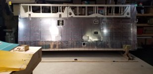


Bdflies
Between Projects
Seeing those trim tabs reminded me of something. Do your best to keep the hinge line interface (front of trim tab and the tab pocket on elevator) as thin as possible. I don't know if mine were fatter than normal, but I struggled a bit to get the tabs in place when everything was covered and painted.
Bill
Bill

robcaldwell
Model B Quick Build Kit
Hope you don't run into the same problem I did AFTER covering the trim tabs. You can see the issue and what I did about it here: https://bearhawk4place.blogspot.com/2018/07/unexpected-fix-for-both-trim-tabs.html
Bdflies
Between Projects
Beautiful work Rob! You are a craftsman! But no. My issue was the hinge barrels to tab and elevator. Sorry, I don’t have pics. I had a hard time pushing the pieces together enough to get the hinge pins in.
I guess the take away is that there are gremlins lurking back there...
Bill
I guess the take away is that there are gremlins lurking back there...
Bill


jim.mclaughlin924
Well-known member

geraldmorrissey
Well-known member
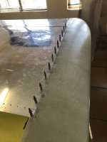
Paul, can you give us some info on modifying the wing tip ro get rhe flush fit.
Thanks
Gerry
Patrol #30
Thanks
Gerry
Patrol #30

In a career first, I scotchbrite wheeled my finger on the bench grinder. It was most uncomfortable and not recommended.


svyolo
Junior Member
Did some work on the Van's baffle kit. I mounted the engine on its mount, and then onto a big engine stand and added a thin plywood firewall mockup. I didn't want to spend 3 or 4 months at the end of the project figuring out one detail at a time. I should have a whole FWF mocked up and ready to transfer to the fuselage when the fuselage is ready.

PaulSA
Bravo Quick Build
Gerry
I am working away at the moment. I'll take some more photos and put something in the "Building Tips" section later in the month.
It's not difficult. If you have quickbuild wings, you have to de-rivet the last rib. Then you insert a 1 1/8" piece of 025 (1/2" on the rib, 5/8" exposed). Match drill and rivet. Fitting the tip requires that you trim out 1/2" ahead of the tip rib so you have a recess. Then match drill the tip to the support and tip rib at about 3" spacing for #6 nutplates. The photo above pretty much shows how it's done. Not difficult - just takes a few hours.
Good Luck!
I am working away at the moment. I'll take some more photos and put something in the "Building Tips" section later in the month.
It's not difficult. If you have quickbuild wings, you have to de-rivet the last rib. Then you insert a 1 1/8" piece of 025 (1/2" on the rib, 5/8" exposed). Match drill and rivet. Fitting the tip requires that you trim out 1/2" ahead of the tip rib so you have a recess. Then match drill the tip to the support and tip rib at about 3" spacing for #6 nutplates. The photo above pretty much shows how it's done. Not difficult - just takes a few hours.
Good Luck!
robcaldwell
Model B Quick Build Kit
Occasionally I will make a video like this one describing my build status. This is as of August 8, 2019:
svyolo
Junior Member
Got my avionics this week. I had my instrument panel cut to outline, and some CF panels laminated. I cut them today. Used a 2 inch hole saw to round the corners in the aluminum. I used an abrasive jigsaw blade to cut the curved parts of the CF. The abrasive blade worked awesome. 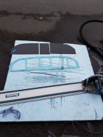
svyolo
Junior Member
Paul, I haven't done that yet. But it has crossed my mind. I am religious about disconnecting air before changing anything on the squeezer.
Imagine a 12 inch drill bit, catching your jeans, close to your nether regions. Don't imagine it for long, it will give you nightmares.
Imagine a 12 inch drill bit, catching your jeans, close to your nether regions. Don't imagine it for long, it will give you nightmares.
robcaldwell
Model B Quick Build Kit
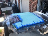
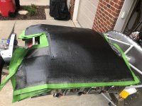
I finished installing the engine side baffles and created a plenum made from carbon fiber. The expectation is for the plenum and coved (rounded) inlets to increase the high pressure side to help keep the CHT’s down. I used SkyBolts on the side panels for quick access to the cylinders and spark plugs. I still need to make a door to access the oil filler tube. I will set the C channels before making the door. This was my first experience working with carbon fiber. Overall, I am pleased with the results.


robcaldwell
Model B Quick Build Kit

robcaldwell
Model B Quick Build Kit
I will probably make the top center cowl out of CF. I will maintain the remaining aluminum.
robcaldwell
Model B Quick Build Kit
I used a high heat resistant epoxy resin from Polymer composites. https://theepoxyexperts.com/shop/ad...ant-fiberglass-carbon-fiber-lay-glue-casting/

m.mooney
Well-known member
Nice! I covered my Rans S7 in Oratex and thoroughly enjoyed the process. Like you mention, it’s more time consuming regarding the attaching of the fabric but it’s airworthy a heck of a lot sooner. The most laborious job was attaching Oratex scrap as anti chafe vs. the standard adhesive tape used on conventional fabric processes.

nichzimmerman
4-Place #1217
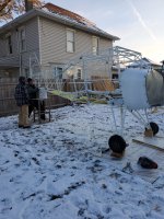
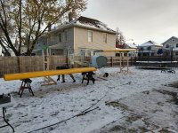
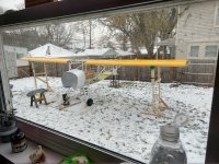
I haven't posted many progress reports, but I figured this milestone was worth mentioning considering I hammered out the first rib nearly nine years ago. Yesterday--after four kids, three pets, six moves, and cumulative years of work-related travel--the scratch-built wings met the VR3-built fuselage right in my back yard. Ambient temperature started at 10F, but most importantly there was zero wind or precipitation. I will add a complete description of the day's events on my new EAA build log and add the link to this post at a later date.
Fun facts: my Bearhawk is already an avid traveler. Ribs were flanged in the DC area, stiffener angles were drilled in New Mexico, attach angles were deburred in northern Africa, and other odds and ends found their way to Europe and S. Korea.
We had a run-in with Physics along the way, as water levels are commonly used to set dihedral, and most water levels are inop in sub-freezing temperatures. We used a solution containing water, blue food coloring, dish soap, and loads of salt. As we set the dihedral of the second wing, we dropped an end and lost some fluid, so I just topped it off with fresh water as the temp had risen to the mid 20's F. We then completed the dihedral measurement and stepped back to admire the work. We immediately noticed the dihedral of the second wing was substantially off. After double checking all measurements and scratching our heads (and breaking for breakfast), we held both ends of the water level together and discovered one side was several inches higher than the other. No freezing had occurred and there were no bubbles. As a guy who does physics for a living, I was stumped. Finally, I realized the saltwater had not really mixed with the fresh water that I added to one side, and the very salty water was significantly more dense than the fresh water, causing a noticeable error. We cleaned out the tube and used only fresh water and finally had a working water level again. We rechecked all measurements and always held the tubing ends together to check functionality prior to making every measurement thenceforth. We also backed up all measurements with a digital level.
Much thanks to my father-in-law for his help (wearing the "cousin Eddy" hat in the photos), and to my wife for providing a constant stream of hot drinks served up in my brand new Bearhawk cup (thanks Jared!). Now it's time to pack up the project for safekeeping as I have another ~6 months of work travel coming up in January =(.
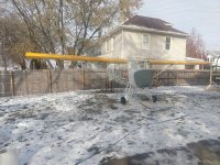

Fun facts: my Bearhawk is already an avid traveler. Ribs were flanged in the DC area, stiffener angles were drilled in New Mexico, attach angles were deburred in northern Africa, and other odds and ends found their way to Europe and S. Korea.
We had a run-in with Physics along the way, as water levels are commonly used to set dihedral, and most water levels are inop in sub-freezing temperatures. We used a solution containing water, blue food coloring, dish soap, and loads of salt. As we set the dihedral of the second wing, we dropped an end and lost some fluid, so I just topped it off with fresh water as the temp had risen to the mid 20's F. We then completed the dihedral measurement and stepped back to admire the work. We immediately noticed the dihedral of the second wing was substantially off. After double checking all measurements and scratching our heads (and breaking for breakfast), we held both ends of the water level together and discovered one side was several inches higher than the other. No freezing had occurred and there were no bubbles. As a guy who does physics for a living, I was stumped. Finally, I realized the saltwater had not really mixed with the fresh water that I added to one side, and the very salty water was significantly more dense than the fresh water, causing a noticeable error. We cleaned out the tube and used only fresh water and finally had a working water level again. We rechecked all measurements and always held the tubing ends together to check functionality prior to making every measurement thenceforth. We also backed up all measurements with a digital level.
Much thanks to my father-in-law for his help (wearing the "cousin Eddy" hat in the photos), and to my wife for providing a constant stream of hot drinks served up in my brand new Bearhawk cup (thanks Jared!). Now it's time to pack up the project for safekeeping as I have another ~6 months of work travel coming up in January =(.
Last edited:
robcaldwell
Model B Quick Build Kit
What procedure did you follow to establish 1 degree of dihedral? Thanks.
nichzimmerman
4-Place #1217
Rob, that is an excellent question and the answer is long enough that I added a paragraph to the post above. -Nic
robcaldwell
Model B Quick Build Kit
I have completed the installation of my engine cowling. And posted an update on my YouTube Channel:

johwiltb
Well-known member
I have completed the installation of my engine cowling. And posted an update on my YouTube Channel:
loved the video Rob! I definitely appreciated the talk about the lower lip you had to do it fiberglass. Slowly learning more and more about aluminum (or in this case, metalwork in general) and figuring out how to spot complex curves is definitely something I’m learning, and this was a great example of some great troubleshooting. Thanks for sharing!

rodsmith
Well-known member
Great video as always Rob! My air induction is nearly identical to your, I also used the James Aircraft inlet filter housing. I don't know if this would work for you, I bought a connection piece from K&N. It is a rubber like material and smooth inside and out unlike scat tube. It is about 3" long. The gap from my filter housing to the inlet on the cowling is about an inch. its not easy to clamp in place but doable and provides a flexible connection.

Archer39J
4 Place Kit Builder
I have completed the installation of my engine cowling. And posted an update on my YouTube Channel:
Great vid! Good idea about the cowl straps, I'm also wondering how I'll do that.
robcaldwell
Model B Quick Build Kit
#svyolo No. The Piper latches I purchased are not inexpensive, but they are very good quality. Occasionally they become available on eBay. As of today, I could not find any current listings for them. Use this search term: "Piper Cowling Latch Kit Complete with Lock Part# 6502-05/ New# 6502-800"
Ray Strickland
Well-known member
Great video, Rob. It is clear that you will have a fine Bearhawk when you are finished. Your craftsmanship is tops.
Regarding your air inlet, I could be all wrong, but you may want to explore Rodsmith’s flexible union between the air box and lower cowl. My 360 with an 80†aluminum prop really rocks on starting. Perhaps your prop, which looks like it may be carbon fiber, may not have so much inertia. I think there is a video on Vetterman’s website which shows how much an engine can rock on starting...beyond what one might expect. Perhaps some other builder/flyers have additional insight.
I look forward to seeing your bird fly. Best wishes.
Regarding your air inlet, I could be all wrong, but you may want to explore Rodsmith’s flexible union between the air box and lower cowl. My 360 with an 80†aluminum prop really rocks on starting. Perhaps your prop, which looks like it may be carbon fiber, may not have so much inertia. I think there is a video on Vetterman’s website which shows how much an engine can rock on starting...beyond what one might expect. Perhaps some other builder/flyers have additional insight.
I look forward to seeing your bird fly. Best wishes.
robcaldwell
Model B Quick Build Kit
I'm equally concerned, Ray. And understand the importance of a flexible connection, as I discuss in the video. I will continue to seek an improved design. I appreciate the feedback and fully expect to receive some challenges on my build, and welcome any and all. Thanks!
robcaldwell
Model B Quick Build Kit
Rod, do you remember what the part # is for the piece you picked up from K&N? I did get some sceet tube (smoother version of scat tubing) from Aircraftspruce, but it has that wire coil running through it.

AKKen07
Well-known member
Finished up my extended floor-level baggage compartment... Pretty close to how I pictured it but not perfect. Being floor level keeps allows me to put longer things on the floor and away from head height in case they become missiles. It goes about as far back as it can, while avoiding cables etc., which allows me to store a 6 foot longbow back there with the rear seat installed (4’ in the extension, 2’ on the floor.)
Attachments


svyolo
Junior Member
I thought about putting it down low, but how many times would I have to empty out the whole plane to get something out? Or how many times would I load up and then realize I forgot to load the long stuff, and have to empty it all out again.
As long as I remember to duck when I hit the brakes I should be OK.........
As long as I remember to duck when I hit the brakes I should be OK.........


SimonNicholson
Well-known member

 Made a start on covering my ailerons.
AKKen07
Well-known member
I flew to New Orleans with my brother then rented a car to drive to Mobile, Alabama where the Continental/Titan engine factory is. There the sales rep, JB, took us on a GREAT tour of the facility. It was worth the trip. Due to some security and proprietary process secrecy needs we weren’t able to film the tour, but I was allowed to take some pictures and I incorporated them into a little post-tour video where my brother and I talk about what we saw. It would have been better if we could have captured more on film but I thought it might be somewhat interesting regardless... The takeaway for me was that these are very high quality American engines made by American workers - even if they are now owned by China. Funny enough there is a little plaque in the lobby that says something to the effect of this company being in the top 5 “business units†of China! Such is life. Still, After learning about how things are done and who does them I feel great about ordering my Titan engine - and Mark got me a great deal on it too.
Here is the vid: https://m.youtube.com/watch?v=CDTFdj1o6KE
Here is the vid: https://m.youtube.com/watch?v=CDTFdj1o6KE

James
4-Place Model A
I was planning to put in the LH main tank today, but I discovered that one of the upper straps has been made too short, and my tank cover won't sit flush :-/
Luckily I inherited a lot of spare strap material, so it's time to make my first tank strap woo hoo!
It's been raining pretty hard here, so during showers I've been stuck inside planning the cockpit fit-out. Today I was researching the ICS wiring - I think I'll just make up 4 drop leads with TP-120 type plugs, and cable tie the leads to the fuselage. Easy to install, no panel-mounted sockets to vibrate loose, and saves me from having to manage two different headset jacks...
James
Luckily I inherited a lot of spare strap material, so it's time to make my first tank strap woo hoo!
It's been raining pretty hard here, so during showers I've been stuck inside planning the cockpit fit-out. Today I was researching the ICS wiring - I think I'll just make up 4 drop leads with TP-120 type plugs, and cable tie the leads to the fuselage. Easy to install, no panel-mounted sockets to vibrate loose, and saves me from having to manage two different headset jacks...
James


Pbruce
Member, Patrol QB
I’m very new to building. I got my rotisserie made out of two engine stands, a couple of u-joints and some steel. It’s way overbuilt and cost way too much since I used a recommended welder who went overboard. (I can’t weld) I learned that cost control is an important element of home building and will keep things under my direct control from here on in.
The good news is that the rig works and I’m able to start installing components inside the wing now.
The good news is that the rig works and I’m able to start installing components inside the wing now.
svyolo
Junior Member
Fabricating stuff like a rotisserie is a great way to learn or get better at welding. I cut my wing crates up and have used the metal for all kinds of fixtures, a wing rotiserrie made mostly out of the wing crates, and a fuselage rotisserie made out of two engine stands like you did.
I did quite a bit of Mig welding on exhausts years ago but always wanted to get better at welding. I wouldn't claim the title of "Welder" yet but I am a lot better than when I started.
I did quite a bit of Mig welding on exhausts years ago but always wanted to get better at welding. I wouldn't claim the title of "Welder" yet but I am a lot better than when I started.

Chewie
Well-known member
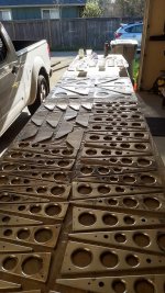
With nice weather this week, I took two days off work to prep and prime the aluminum flap and aileron parts. I used Stewarts ekoprime with a touch-up Finex spray gun and was very pleased with the results; they make a fine product. The finish is smooth and solid except for a few spots (mostly flanges that are hard to hit) that I need to touch up today. I ran out of room to lay out the spars and skins, they're next.
Hats off to you guys who can work on your build for 6-8 hours a day... I'm not used to this, it's exhausting!
Hats off to you guys who can work on your build for 6-8 hours a day... I'm not used to this, it's exhausting!
Attachments


Last edited:
Chewie
Well-known member
Olm ,
Great question. I'm not entirely sure. The numbers I've seen are:
Stewart Systems: 0.8 oz/sf = 7.2 oz/sq yd
Bob: 0.1 lb/sf = 14.4 oz/sq yd
Realistic numbers from this forum: 10-20 oz/sq yd
Oratex...?
Obviously the finish and my skill level will play into it! I'm holding off balancing the ailerons as long as I can, maybe even after covering. What's your approach?
Edit: If you're asking just about the bare fabric... I'm not sure on that either. Need to research.
Great question. I'm not entirely sure. The numbers I've seen are:
Stewart Systems: 0.8 oz/sf = 7.2 oz/sq yd
Bob: 0.1 lb/sf = 14.4 oz/sq yd
Realistic numbers from this forum: 10-20 oz/sq yd
Oratex...?
Obviously the finish and my skill level will play into it! I'm holding off balancing the ailerons as long as I can, maybe even after covering. What's your approach?
Edit: If you're asking just about the bare fabric... I'm not sure on that either. Need to research.
Last edited:

JimParker256
Bearhawk Enthusiast
....
Oratex...?
From the https://betteraircraftfabric.com/common-questions.html page:
"Oratex600 weighs about 3 ounces per square yard." Since it is rated for use on airplanes up to 600 Kg (1323 lbs), so it would be appropriate for the LSA.
"Oratex6000 weighs about 4 ounces per square yard." This is the one for the rest of the Bearhawk fleet.
"Oratex6000 weighs about 4 ounces per square yard." This is the one for the rest of the Bearhawk fleet.
Mark Goldberg
Bearhawk Aircraft
When I was buying Oratex for my LSA, I did the calculation of how much more weight the 6000 was compared to the 600. I don't remember but thought the difference was small enough that I went with the heavier fabric. Mark

Olm
Junior Member
Nice to see mere experienced guys are taking part in the discussion! I balanced my ailerons and without covering the weight is about 1,4 kg.(3,08 p) and thinking of leaving the hole in covering to be able to add some more weight into the balancing tube. We have in Russia Dacron poly for reasonable price it is 250 gr per m2(0,46 lb/yd2) and another 125 gr/m2 (0,23 lb/yd2). And to the theme, at the summer country-house begun assembling the flaps.
Attachments

Last edited:

spinningwrench
Patrol
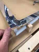
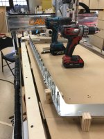
Today I machined a bezel for the pilots window out of .025" aluminum. I made it as a solid piece with some corner radiuses. I am going to pop rivet it to the window frame and sandwich a piece of .093" Plexiglas between the bezel and window frame. That will be my complete window system. I am not going to use bent up aluminum strips in the interior for backup as the window alone makes for a very rigid installation.


Attachments


spinningwrench
Patrol
The blocks have a 1/2 round slot to mate with the steel window frame and the edge of the jig gives the proper 1/2†bezel overlap on three sides and flush on the top. 2nd jig in the works for exactly drilling the tubes in dead center so the bezel will not be wonky when the rivers are put in

TimTall
Well-known member
Today I test fit my exhaust system headers. I'm relieved that it fit perfectly. Clinton at Custom Aircraft Exhaust did a great job working from my hand sketched drawings to get it bang on!. There's not a lot of room in these cowlings for the IO-470! We managed to get 1" of clearance or more to every piece of structure, the cowling and the spark plug on the fwd left cylinder.
The tail pipes can wait until the engine is mounted in the airframe.



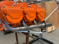

The tail pipes can wait until the engine is mounted in the airframe.
TimTall
Well-known member
Don't worry about being that guy. That's why I posted here. I want opinions. There's seal-less slip joints at the connection to the tail pipe on both sides. Clint thinks that'll be enough. He's been building these for 40 years so I hope he's right. He definitely gave me some recommendations for how to secure the tailpipes to the airframe and to each other to avoid putting any torque back into the headers.
I'm not sure there would have been any room to have a typical slip joint in the header anyway.
I'm not sure there would have been any room to have a typical slip joint in the header anyway.
rodsmith
Well-known member
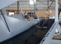
Finally painted my floor boards with Stewarts acrylic metallic grey. Supposed to be pretty tough. I had made the floor boards a few years ago but was not happy with the fit of the most forward one, plus I had to move the fuel selector. So remade the front one and painted them. Weight of the .032 AL without paint was 12#-6oz. Paint added 8 oz. I may replace them with a carbon/kevlar laminate but not before I fly. Interior fabric paint is Stewarts Ekopoly, non metallic silver with flattener added to reduce the gloss, I like the way it turned out.
Last edited:
svyolo
Junior Member
I finally got around to starting the fuselage covering. I applied the fabric (Oratex) to the two upper sidewalls, and am almost done cutting the ceiling (aft of the skylight). Hopefully I will be done in 2-4 weeks, and hang the motor. A bunch of little super magnets really come in handyto hold the fabric in place
JimParker256
Bearhawk Enthusiast
Great tip about the magnets! I would not have thought of that, but it's a really smart idea! I think I would avoid using them anywhere near the eventual compass mount location, however...
spinningwrench
Patrol
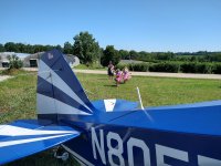
Decided to take my Bearhawk out for fresh air today as I moved it to the airport. U-Haul auto movers have just the right wheel spacing for a Patrol. I had to rig up a wood structure to support the tail wheel as the trailer is 3’ short.



Russellmn
rock star
Syvolo, what do you think about the Oratex? I'm seriously considering using it on mine (when I get to that point) in a constant quest to add lightness.
Jim, I would be quite surprised to find that those little magnets could impart enough, or any, magnetism to the steel to alter a compass reading. Though I've been wrong before...
Jim, I would be quite surprised to find that those little magnets could impart enough, or any, magnetism to the steel to alter a compass reading. Though I've been wrong before...
I started up my Barrows O540 today and got the idle speed and mixture adjustment on the carb set. Even without a primer with the SureFly electronic ignition magneto the engine started right up which was a relief of course. The only issue was the Newton fuel selector valve was sticking and hard to switch to different positions. It was 104 degrees today in Southern Cal so that it’s hard to much done.

rv8bldr
4A Scratch Builder
Hey everybody
I've been using up some left over vacation from last year working on the boot cowl and cowl for my 4pl. It has been STINKING hot and humid around here lately so not a lot of fun, but I have gotten quite a bit done. The pictures below show about 70 hours worth of work. I hung the engine, mounted the prop, got the nose bowl in place with spacers, then got to work on the metal.
I have a rather tall panel (I'm putting the portrait Garmin G3X GDU 370s in), and I wanted a straight line from the panel to the nose bowl so I started by making a sign board template of the firewall, then made the firewall from that.
Once that was done, I mounted the panel and got the boot cowl parts made (the side panels are removable). Then I got to work on the main cowl.
Once the cowl shape was done (just clecoed and screwed), I cut a hole in the bottom (scary) for the fuel servo. I am using a Van's Aircraft filter airbox and a massively hacked up RV-6 chin scoop for the air intake ala Michel Roy. I have attached before and after pics of the chin scoop. Canadians will recognize the clear hockey shin pad tape holding the scoop on
It kinda has a C-170 vibe going with that long, straight top cowl.
Tomorrow the fiberglass work starts to make the chin scoop mountable, aerodynamic, and non-ugly. I hate fiberglass....
I've been using up some left over vacation from last year working on the boot cowl and cowl for my 4pl. It has been STINKING hot and humid around here lately so not a lot of fun, but I have gotten quite a bit done. The pictures below show about 70 hours worth of work. I hung the engine, mounted the prop, got the nose bowl in place with spacers, then got to work on the metal.
I have a rather tall panel (I'm putting the portrait Garmin G3X GDU 370s in), and I wanted a straight line from the panel to the nose bowl so I started by making a sign board template of the firewall, then made the firewall from that.
Once that was done, I mounted the panel and got the boot cowl parts made (the side panels are removable). Then I got to work on the main cowl.
Once the cowl shape was done (just clecoed and screwed), I cut a hole in the bottom (scary) for the fuel servo. I am using a Van's Aircraft filter airbox and a massively hacked up RV-6 chin scoop for the air intake ala Michel Roy. I have attached before and after pics of the chin scoop. Canadians will recognize the clear hockey shin pad tape holding the scoop on
It kinda has a C-170 vibe going with that long, straight top cowl.
Tomorrow the fiberglass work starts to make the chin scoop mountable, aerodynamic, and non-ugly. I hate fiberglass....


