Tell us what you did today on your Bearhawk Project

Got 50 each -5 forward spar capstrip rivets squeezed today. This is my last spar, so glad to see the end coming. Should finish all the spar work next week. Then I plan to carefully wrap them up and store them. I need a break from aluminum, got an urge to work with steel. So I'm going to build the empennage, then go back and finish the wings. Looking forward to cutting, grinding, bending and welding.
Gerry
Patrol #30
 
I did a test hang of the engine yesterday to locate, exactly, a very tight fit of the Vans oil cooler mount. And check everything else i mounted. Then I removed it. Worked good. Today I reinforced the oil cooler mount on the firewall, and 1/2 the battery box. Holiday weekend I need another piece of angle. The oil cooler mount is rock solid. I used some 1/2x1/2 x1/16 angle for the oil cooler. The angle overlaps the tubing under the firewall, and is clamped in place with unpadded Adel clamps with #8 clip nuts on the clamps (thank Colin, I love the clip nuts on Adel clamps. The Earthx battery box reinforcement is not yet done.

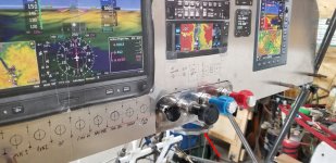
Everything else was good. I have had the engine mounted on its mount, and mounted onto an automotive engine stand with a firewall/instrument panel mockup to do wiring, systems, etc. So far so good. FWF finishing should be a couple of days, then build the cowling.
 

Attachments

  • ENGINE.jpg
    ENGINE.jpg
    2.3 MB · Views: 0
  • 20210904_151553.jpg
    20210904_151553.jpg
    2.4 MB · Views: 0
  • 20210904_151608.jpg
    20210904_151608.jpg
    2.3 MB · Views: 0
  • 20210905_140918.jpg
    20210905_140918.jpg
    1.8 MB · Views: 0
  • 20210905_140928.jpg
    20210905_140928.jpg
    1.8 MB · Views: 0
  • 20210905_140950.jpg
    20210905_140950.jpg
    1.8 MB · Views: 0
Last edited:
SV - I doubt this is new info for you but my A&P friend advised me not to put unpadded clamps on steel tubes. He says they will slowly wear through them. I've padded mine with thin teflon tape etc., although it doesn't help the fit of the clamps I haven't found anything better.
 
I have found the rudder trim in my Maule (such as it is) really useful, especially on long climbs. In addition, depending upon speed, I have had to fiddle with the setting to get things where I like it. If you aren't familiar with the Maule rudder trim, it is essentially a handle you tug on that just pulls on your right rudder pedal with a spring. Dead simple. Also, right trim only :-)

Since I am putting an electric elevator trim in my 4pl (actually, a G3X system with AP and YD), I had the trim wheel left over. Not wanting to have a rudder trim tab sticking out the back of the airplane and only being trimmed for one speed (unless I have built everything perfectly straight...not likely since this is a scratch build) I thought I would try and design and build a rudder trim system that is completely adjustable.

Here it is.

Rudder Trim 1.jpg

I have put a red arrow pointing to the trim wheel under the throttle mount.. The wheel is snugged up using an AN310 nut using the right combination of washers to get the right friction so that it can be moved by hand but not by the rudder return springs. NOTE: I know there is an AN365 there right now. It was what I had handy doing the fit-up. It will be replaced after covering...


Rudder Trim 2.jpg

Here the arrows point to the trim wheel and the rudder return spring(s).


Rudder Trim 3.jpg


The cable then goes through an upper pulley, travels down the tube, and through a second pulley (just out of view).


Rudder Trim 4.jpg


And finally the lower pulley and the shackle attachment to the rudder cable assembly.

Probably overkill, but it was fun to make and I am sure that I will use it.
 
I hung the engine again just to make sure everything is playing well together. I finished up making a few fuel lines, and the oil cooler and filter lines. Made a wood disk to start on the cowling,
Last week I made a bunch of reinforcements for things mount on the firewall. For lighter weight stuff I just made a .032 or .025 doubler of larger area, and broke the edges for stiffness. Heavier stuff I used mostly .025 or .032 angles to carry the load to a tube behind the firewall, either mounting tab or Adel clamp with a clip nut. Battery, fuel pumps, and oil cooler. They feel pretty solid. I don't know how anybody else did stuff like this, but my Ti firewall is pretty flexible.

I did screw up and my throttle cable is 1" too short. I went on ACS and typed "throttle cable extension". Sure enough, I wasn't the first person to do this.
 

Attachments

  • RFIREWALL1.jpg
    RFIREWALL1.jpg
    2.1 MB · Views: 0
  • FUELFILTER.jpg
    FUELFILTER.jpg
    2.9 MB · Views: 0
  • OILCOOLER.jpg
    OILCOOLER.jpg
    2.2 MB · Views: 0
  • NOSEBOWL.jpg
    NOSEBOWL.jpg
    2 MB · Views: 0
  • BATTERYMOUNT.jpg
    BATTERYMOUNT.jpg
    1.9 MB · Views: 0
The closest thing to a BH I ever flew was a T-34C in Navy flight school. It was a bit better, or worse, depending on how you look at too much power. It had 3 axis trim. But, it was meant to train people. It was supposed to be hard. Going from 100 to 200 kts was still one of the hardest maneuvers I can remember doing. Continuously triming in all three axis.

The purpose of a BH is different. I am pretty sure I won't fly it the same way. But I like the idea of rudder trim. But having not flown anything like a BH I will keep it simple for now. But I have thought about it.
 
On my installation the throttle cable was also too short (IO540). Vans sell a cable for their O360 that is longer and fits well in my case.
 
I'm using Stewart's for my fabric interior. I work alone at my home workshop. I have no fabric experience. I've never painted anything before. Last march I set a goal of having my fabric/paint completed for the entire aircraft about now. (meaning my schedule has been scrapped.)

I took a Stewarts class in March with AKKen07 (see post 615...He's done!!) And yesterday I ended up with a shiny orange peel surface. The second photo makes the orange peel really stand out, but now it seems to be either flowing out and getting better, or I took a photo that magnifies the surface texture. I do not desire a finish like a new refrigerator. It's got some texture, but absent are any even minor foundational flaws like fish eyes or drips. The interior has so many obstacles for the paint gun to bump into its hard to paint with material flowing good out of the gun. I expected an orange peel look because I kept the flow out of the paint gun low due to obstacles.

I fabricated my own paint booth using 1" diameter thin wall metal conduit. Its 10 x 20' and has two 20" box fans in the ceiling. Filtered air enters from furnace fitters that I taped to the box fans. Air exits out of the booth at the opposite end through more filters. I had no overspray contaminate my workshop. The "booth" pressurizes and enlarges with the fans turned on. Now that I'm done, I'll just keep the sides clamped to the upper frame until I am ready to paint the fuselage.

So I'm thinking maybe I'll get the fuselage and everything else covered this winter, and paint in the spring. I will cover, and rib stitch, and install all inspection covers, and all else I can think of, stopping before I need to do my first coating....which is sealing the fabric. If that gets accomplished before Michigan's spring time warm up, then I'll ro-do the boot cowl, install windshield, and mate up the wings/windhield and fabricate the wing root fairings.
Click image for larger version  Name:	Screen Shot 2021-09-26 at 11.35.53 AM.png Views:	45 Size:	744.2 KB ID:	68473Click image for larger version  Name:	Screen Shot 2021-09-26 at 11.36.08 AM.png Views:	46 Size:	354.9 KB ID:	68474
Click image for larger version  Name:	Screen Shot 2021-09-26 at 11.35.53 AM.png Views:	45 Size:	744.2 KB ID:	68473
 
Last edited:
For me, I found that equipment made HUGE difference. Continuous high output compressor, (I went with a Eastwood scroll compressor), a quality air dryer, high flow lines and fittings, and the Devilbiss paint gun recommended by Stewarts. I swear that alone really made the difference for me. I only encountered orange peel when I tried painting aluminum when it was too cold outside.
 
I Also followed every Stewarts Recommendation. An Ingersol Rand, like 15 CFM, 5 hp, 220V, 21Amp is a lot of bang for the buck, but louder than your scroll compressor I bet. The got the best filter/dryer I could find and installed it at the wall where the air line hooks up, and the High Flow Fittings from Stewarts.

I'll by your Finish Line your paint gun! Stewarts tells us DeVilbiss discontinued it and Stewarts stock is sold out. They have replaced it with another product. I bought both the smaller Devilbiss gun Stewarts offers and their new offering (a finish Line replacement). I used the smaller gun for the interior, and have not touched the Finishline Replacement gun yet. But I loved the DeKups paint reservoir system on the smaller Devilbiss gun, and the new gun does not have that option available.
 
Last edited:
Watch Sir Newton Folks. His talent is amazing and he will improve it with simplicity that will beg me to ask the question "Now why didn't I think of that?"
 
I decided to replace my aluminium tunnel with a stainless steel one, it makes perfect sense that the firewall and tunnel must be stainless steel. If you have a FWF fire, it will blow through the tunnel. I have my header tank at the back end under the tunnel, for me its very important and I will also add some heat shield between the tank and the heat shield. Click image for larger version  Name:	757D8D69-0976-420B-8064-57E437F3C5F8.jpeg Views:	0 Size:	646.7 KB ID:	68512
 
Last edited:
Oh yeah, I'm going to have to do some substantial upgrading. My 22 year old Coleman 27 gallon compressor ain't gonna get the job done. Looking hard at a scroll compressor. Big coin!
 
For the interior I used Stewarts non metallic silver and flattener. I used the full amount recommended, still a very shiny satin finish. Your surface finish is not bad, might try a little more air pressure or thinning slightly more. It does flow out for a few days so will be smoother than when first sprayed.
 
I don't know if they still sell the Devilbiss Teckna Pro lite. It's more expensive but a very nice gun. I got a new one on Ebay for a substantial savings.
 
The Devilbiss Tekna Pro Lite indeed is the smaller gun that Steweart's sold me. The Stewarts offering includes the right size tip to apply their products and the DeKups liquid reservoir setup. (DeKups is like a J&J baby bottle that allows an infant to suck milk out of a bottle without overcoming the effects of gravity by using a plastic baggy housed in a cylinder. It allows the paint gun reservoir to feed fluid with the gun upside down and nothing spills )
 
FYI, This compressor will power a Devilbiss Finish Line Paint Gun. https://www.tractorsupply.com/tsc/p...linder-pro-air-compressor-60-gal?cm_vc=-10005

I waisted a day or so shopping for a used one. Know what to listen for if you go the Craigslist route. Don't settle for anything you think might knock just a little. When I'm done with my new compressor I think I can sell it & do OK. I might like painting though.

That compressor I listed is 70 Db in my shop when it runs as measured on an iPhone app. A scroll I looked up is "as low as 63 Db" and will never wear out. The traditional compressor is about 7000 hour life. If you see something less (like 1000hr life) keep shopping (DeWalt).
 
Got the wings painted a few days ago. That’s all the painting for now since it’s getting pretty cold out and I rely on airflow from outside. Still need to paint a couple dozen small parts and need to cover and paint the flaps and ailerons in the spring.
I basically am using the same system as Rob to get the job done. One thing I struggle with is water in the air system. My filter catches it but needs replacement too often (at $65 a pop!) I resorted to putting them in the oven at 200 degrees for a couple hours to dry them out. Then I forgot it was in there and set the oven to 400 for dinner… :/ oops.
I’ve found that the topcoat goes on well with three real light fog coats then a heavy wet coat. I like how things are turning out but you have to lay the topcoats on REALLY heavy to get the nicest finish, hopefully I can polish a bit of orange peel out later if it still bothers me.
 

Attachments

  • photo10138.jpg
    photo10138.jpg
    918.4 KB · Views: 0
  • photo10139.jpg
    photo10139.jpg
    1.5 MB · Views: 0
The water problem can be solved if you put a condenser down stream of your compressor, I will use a automatic transmission cooler mounted in a shady spot on the outside of my hangar to cool the air so the water can condense and drop out of the stream. Then into another receiver. Desiccant cartages are great for polishing the air afterwards but not really required if you can get a good enough temp drop across a condenser. I never have problems with humidity in the air. Free knowledge bomb for the person that is painting his BH with the exact same colors I painted my PA-140 with years ago. FYI those colors are also a hockey teams colors. The Edmonton Oilers! Great team they consistently lose. :-(
 
Last edited:
I made a cheap air cooler/dryer and it works well. I took about 50' of copper tubing and coiled it up in a garbage can. I put a drain at the low point of the coil and a drain out of the garbage can. I run a garden hose with a light mist on the tubing while I'm painting. It catches a lot of water and the air leaving the coil is cooled to room temp or cooler. I have decent shop compressor but it's not quite enough volume so I tee'd in a smaller compressor. No problem holding 27psi at the gun indefinitely.
 
Currently air leaves the pump of my compressor and flows through an 8 inch long small copper tube into the top of the tank. The short copper tube is too hot to touch when the compressor is running. Why cant the air can be cooled after it leaves the compressor pump prior to it entering the tank? Huge temperature differential exists and it ought to cool well. So, I maybe if the air left the compressor, then went through a 25'long coil of tubing that had air flowing over it from the fan associated with the compressor pump's fly wheel combined with a water trap prior to the tank, it could do a lot of good.
 
Thanks for the tips guys! If I get some slow time this winter I’ll try to incorporate a fix for my system.
Sir Newton, those are also the colors of the Denver Broncos :) I guess lots of good folks like ‘em!
 
I pulled the motor for the last few bits to add to the firewall. I never used Aeroquip style hose before, but learned quickly and glad I bought reusable fittings. I mounted the engine on a stand with a firewall mockup and instrument panel to slowly mock up how everything should work, and it almost all did. Maybe the only thing that didn't was 1 plumbing thing. (so far). Rigid or racing hose needs a bend to make installation, or removal, easy, or even possible. A 90 bend is best. If you don't plan on removing it, no worries. I knew this, but my low pressure fuel filter, on one end, was a straight fitting. That would have required removing a bunch of screws (hard) on the fuel pump cover, removing that line, and then being able to remove the line to the filter. So I ordered a speed flow 90 degree fitting, to screw into the fuel filter, so I can use an Aeroquip style fitting on the fillter, to make servicing the filter easier. i will post some pics tomorrow.

Reusable fittings for the fuel and oil cost more in the beginning, but saved me money. Probably several hundred dollars.
 
Would you author a thread....maybe in "Building Tips" to expose us to the type of Aeroquip Hose and model of Reusable fittings that you found ideal, the tooling to fabricate a line and link of a "how to fabicate" video?
 
I can do it, but there are a bunch of youtube videos on it. I will start a thread, and include links to the better youtube videos, and stuff I learned. I am super glad I bought re-useable fittings, as I doubt I didn't redo less than 70% of them. In particular, the bigger fittings for the oil lines are a lot bigger than I would have thought, and that changed the geometry of how they worked together.

I think the way I ended up doing the oil filter and Van's oil cooler mount (very similar to what Nev did) Is about as simple as you can do it, but the geometry of the fittings is still huge, and not what you might expect.

Starting out, I actually sort of "knew what I didn't know". I went with re-useable fittings because i knew I wouldn't get it right the first time. They are more expensive, but saved me money in the end. The cheapest, if you knew exactly what you were doing, would be crimped hydraulic hoses from a local shop.

But I will resurrect another thread, or start another one, and mostly include links. The videos are better than anything I could do.
 
This weekend I mounted two cabin heat cables and made brackets in the cockpit, and fitted them. Also two cables for an unbuilt cowl flap, and alternate air inlet which is built, but not installed. Almost finished up power "big wire" power supply wiring. I was short 1 connector. Hopefully first "Master on" tomorrow. I have had the engine on and off a couple of times the last 2 weeks, never took the engine off the hoist. I wanted to make sure all the big stuff played together well. Almost all of it did.

Hopefully no "smoke check" tomorrow.
 
No smoke, only a couple of minor errors. Avionics master switch is mounted upside down.

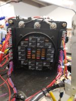
I used a commercially available switch/relay panel meant to be the electrical system for a vehicle. Two separate buses, all wired up according to the aeroelectric connection, 1 alt, 2 batteries. Minimal switches, just enough to check backups (ignition, fuel pumps, and 2 voltage regulators). Pitot heat and strobe lights in the wing root, LED position lights come on with the avionics master.

The relay panel weighs about the same as a VPX. Very ruggedly made, IP67 or 68, I can't remember. There is a sealed cover that goes over the relays/fuses. It massively reduces the number of terminals per circuit.

The relays are all dual pole. In normal flight, none of the relays will be energized. Only the master relay is energized once everything is up and running.

So far so good.
 

Attachments

  • PANEL1.jpg
    PANEL1.jpg
    2.4 MB · Views: 0
  • panel2.jpg
    panel2.jpg
    2.1 MB · Views: 0
Hello guys, I'm new here so forgive me if I'm positing incorrectly, I just received my quick build Model B, and I'm wondering if anyone else is experiencing issues, with the fit of there trim torque tube.

Byron D.
 
Hello guys, I'm new here so forgive me if I'm positing incorrectly, I just received my quick build Model B, and I'm wondering if anyone else is experiencing issues, with the fit of there trim torque tube.

Byron D.

Ha, I did my fitting yesterday (Companion QB Kit) It took time, it was a slow process sanding out the holes for the tube on all four fittings (2 each side). Go slow
 
Hi Byron, welcome ! Try posting your message as a new post under General Discussion - New Topic.
 
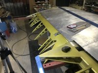
Spent the day making access port frames up for the left wing. So far so good with the exception that I got ahead of myself and riveted all the nutplates on before match drilling to the wing skin. Anyway, that'll resolve itself somehow.

Having finished the right wing now, I had spent hours and hours research how to do each part, the instructions were only a small help and in some areas incorrect. The result is that the left wing is progressing much faster. The aileron balance cable is already installed, tank cover nutplates drilled and countersunk, wing-end nutplates drilled and dimpled, bellcrank installed etc.

Click image for larger version  Name:	2B7FEE1C-42AA-4CDB-8B73-FF2E824F038A.jpeg Views:	0 Size:	356.3 KB ID:	68946

Click image for larger version  Name:	2B7FEE1C-42AA-4CDB-8B73-FF2E824F038A.jpeg Views:	0 Size:	356.3 KB ID:	68946

Click image for larger version  Name:	2B7FEE1C-42AA-4CDB-8B73-FF2E824F038A.jpeg Views:	0 Size:	356.3 KB ID:	68946


Click image for larger version  Name:	2B7FEE1C-42AA-4CDB-8B73-FF2E824F038A.jpeg Views:	0 Size:	356.3 KB ID:	68946

Click image for larger version  Name:	2B7FEE1C-42AA-4CDB-8B73-FF2E824F038A.jpeg Views:	0 Size:	356.3 KB ID:	68946

Click image for larger version  Name:	2B7FEE1C-42AA-4CDB-8B73-FF2E824F038A.jpeg Views:	0 Size:	356.3 KB ID:	68946
 
svyolo - it looks like we are going down a very similar road here (at least in my imagination, which is where all my electronics currently reside...). I am looking at how to plot all this on my firewall - especially the 2 batteries. How did you arrange them?
 
Curious about the trim horns, I cannot see anything on the dwg that calls out a 5/8" through hole at the center of the horn for the T-9 tube. I'm in the process of building these right now. Hole or no hole?
Thx
Gerry
Patrol #30
 
Curious about the trim horns, I cannot see anything on the dwg that calls out a 5/8" through hole at the center of the horn for the T-9 tube. I'm in the process of building these right now. Hole or no hole?
Thx
Gerry
Patrol #30

Good question, from what I can see on the plans is that the trim tab is welded to the t9 tube, and that t9 tube is then bolted to a t5 tube that is passed through the trim horn.

I may be misinterpreting this though so hopefully another builder can chime in!
 
If the patrol is like the 4 place the two trim horns bolt together. There is a T5 tube from each side that bolts to the trim horn. The hole in the center is not needed but I also do not think it’s a problem. It will have enough strength and be plenty stiff from the welded tube. You could double check that with Bob.
 
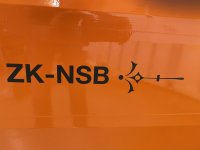
The sign writer came today and applied the decals. I've applied to the Civil Aviation Authority for a personalised call sign, based on having an identifiable paint scheme, which has been provisionally approved. This allows me to not have to display a registration, or display it in my choice of size, hence the much smaller than regulatory registration lettering.

I gave the sign writers some initial ideas, but left the overall design up to them. This is what they came up with.

Click image for larger version  Name:	0C171549-1E26-421F-8D07-0F8D47D594A6.jpeg Views:	0 Size:	2.03 MB ID:	69302

Click image for larger version  Name:	0C171549-1E26-421F-8D07-0F8D47D594A6.jpeg Views:	0 Size:	2.03 MB ID:	69302

Click image for larger version  Name:	0C171549-1E26-421F-8D07-0F8D47D594A6.jpeg Views:	0 Size:	2.03 MB ID:	69302

Click image for larger version  Name:	0C171549-1E26-421F-8D07-0F8D47D594A6.jpeg Views:	0 Size:	2.03 MB ID:	69302

Click image for larger version  Name:	0C171549-1E26-421F-8D07-0F8D47D594A6.jpeg Views:	0 Size:	2.03 MB ID:	69302

Click image for larger version  Name:	0C171549-1E26-421F-8D07-0F8D47D594A6.jpeg Views:	0 Size:	2.03 MB ID:	69302

Click image for larger version  Name:	0C171549-1E26-421F-8D07-0F8D47D594A6.jpeg Views:	0 Size:	2.03 MB ID:	69302
 
Last edited:
Thanks guys. Fuel gauge markings will have to be calibrated first, which I'll do on some tape. A friend is able to make placards similar to the engraved pax warning so we'll do it that way. One small issue was that the vinyl transfer letters don't adhere well to Kydex due to the rough surface. Hence why we engraved it onto an aluminium placard and used strong double sided tape.
 
I used a different technique, and always match drilled the actual hinge bolt hole. But there is variation in how they are all made. They are very accurately, made but not perfect. You can end up with a few without enough material on one side of an edge or another. I lacked the equipment to bend 4130 that thick so had to order more.
 
I don't think they do - at least mine were not pre-drilled. It's an area that would be greatly improved by pre-drilling. I ended up having to re-make one hinge, which involved getting a local machining shop to do the bend. I took a lot of care, but had difficulty aligning two of them. The pockets that they install into are difficult to access with hands.
 
I made my first set of cowl plugs, definitely learning how to do it better if there is a next time.
IMG_20211104_200429510.jpg
I should have made the side panels about twice as thick (I used 2") and on the first one I didn't route the connecting webbing properly.
 
This was kind of a test case for that. Building them makes it easier to decorate them, since we can do that before assembly. The question is whether it will be worth it to train my young workers to be able to sew well enough, and whether they will be interested.
 
I’m along way behind Nev, but I am closing in on finishing the wings.
 

Attachments

  • photo10517.jpg
    photo10517.jpg
    1.6 MB · Views: 0
  • photo10516.jpg
    photo10516.jpg
    1.6 MB · Views: 0
  • photo10518.jpg
    photo10518.jpg
    1.9 MB · Views: 0
  • photo10519.jpg
    photo10519.jpg
    2.5 MB · Views: 0
Looking very good Scott, and very close to being finished.

Incidentally, how will you attach the other end of the pitot tubes to the pitot aluminium tubes. Mine slide over, but there must be a way to clamp them in place.
 
I’m not home to take a photo but there are push on fittings that will connect to the aluminum lines. My Pitot tube is different than the Dynon system. Look at this kit from Stein

https://www.steinair.com/product/pitot-static-tubing-port-kit/#

If you look at the image there are aluminum fittings that connect to a flare on the pitot tube lines. They end in a NPT threaded end and you can screw push on fittings to that end. They are the gold colored fittings in the image.

I hope that make sense. I used that system on my RV and it has been leak free from five years.
 
If you have a standard aviation flaring tool you can flare those small aluminum lines on the pitot and AOA tube from Dynon. Just make sure the compression fitting and B nut are on the tube first. I have made that mistake. You may need to wrap some tape around the aluminum tube to keep it from slipping in the flaring tool.

The nylon lines just push in and lock in place. To remove the nylon line just push down on the round ring at the top of the fitting and the nylon line can be pulled out. Make sure the line is cut straight to ensure a leak free connection.
 
I started with mine with flared ends and everything but they both cracked and leaked. This could have been more a reflection of poor execution than a bad idea. But when the first one started leaking the avionics shop caught it, and they had a much easier solution. We just left the pitot outlet as it came from dynon, and slid a soft rubber line over that and also over the 1/4" hard plastic pneumatic line. It was much lighter, cheaper, and more durable.
 
Back
Top