Tell us what you did today on your Bearhawk Project

My front engine stand is the same, I used a lighter engine stand at the tail. For the fuselage rotisserie I just used a couple of pieces of 2x2 wood, screwed together, and held to the bottom of the engine stands as a connector using U clamps. It is a bit dangerous to not have a connector. Your front stand is probably a bit safer than the rear.
 
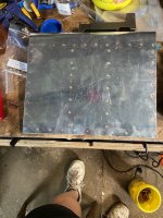
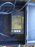
I rejuvenated a Harbor Freight hand-me-down blast cabinet. LED, new gloves, dust collection and even a grounding wire. This paves the way to finally painting the bellcranks, pulley retainers, torque tube support and whatever other little steel bits I can find prior to skinning the wing.
 

Attachments

  • photo12022.jpg
    photo12022.jpg
    1.7 MB · Views: 0
Boot Cowl
Some Boot cowl parts were fabricated three times. I was not real pleased with my first attempt from a few years ago but did not understand why. Then I saw Colin Campbell's work on the Five at OSH and understood that my Instrument Panel (Kit circa 2017) should have been trimmed down and that impacts how the sheetmetal rolls around the corner at the 10:00 and 2:00 position. It's a high visual impact area. Its right now. I can remove the side wall of each boot cowl with a phillips screw driver. I can remove the top and the windshield with the same.
Click image for larger version  Name:	IMG_4646.png Views:	0 Size:	5.28 MB ID:	75936Click image for larger version  Name:	IMG_4647.png Views:	0 Size:	5.28 MB ID:	75937
Windshield positioned
So, Boot cowl is done. I fit the windshield. I keep my wings on a set of stands, and I attached them to the fuselage so the line with the wing leading edge lined was good without needing to guess or measure or worry. Trimming the windshield with a 4 inch angle grinder bearing an abrasive pad worked great. I always had a line to reference when I trimmed it. Very little time was spent trimming it up, but I bet 30 times it went on and off. I bet not more than two minutes for each trim. After its all trimmed the raw edge got filed and sanded to prevent stress risers.

I use regular cellophane packaging tape for my release agent and applied artists clay to the fillet between the windshield and boot cowl (gray). There is lots going on in this area. I spent time and attention to learning how the windshield, and door and L/R windows interact when opening and closing them.
Click image for larger version  Name:	IMG_4674.png Views:	0 Size:	5.46 MB ID:	75938Click image for larger version  Name:	IMG_4699.png Views:	0 Size:	5.16 MB ID:	75939
Windshield Fairings
Windshield Fairing and Back-up Strip are fabricated, the Back-up strip is installed. I used 8.8oz bi-directional fiberglass fabric and AeroPoxy epoxy. The epoxy is mixed by weight rather than pumps, which saves a lot of waste and money. A qt is about $75. A scale is not expensive. I've never had a batch fail, even in 50-60F temperature.
Click image for larger version  Name:	IMG_4737.png Views:	0 Size:	5.64 MB ID:	75940Click image for larger version  Name:	IMG_4724.png Views:	0 Size:	5.41 MB ID:	75941Click image for larger version  Name:	IMG_4733.png Views:	0 Size:	5.70 MB ID:	75942 IMG_4734.png
 
Last edited:
Thanks Archer. I think data shows that I am a slow builder. I don't have a time based goal...at all. When I started this project I would get angry. Something in my shop culture had to change. I need an error tolerant culture in order to be resilient when I am learning. Self judgment and condemnation are destructive.

Now I have a quality based goal, and educate myself often times through experience (aka errors). It cost money and time to get any education, and I suspect that my costly "lets make it over again" shop culture is faster and cheaper then a class room. I work alone at my home. A mentorship is better, but there is no one at home. so here I am. Because I have structured an "Educational" and "Quality" based environment errors and re-doing tasks to get the job "done well" becomes encouraging. It just take me longer.

So this website. along with relationships I am building with you all, is a big part of my build.
 
Last edited:
Click image for larger version  Name:	A091152A-FC60-477D-A7FD-F2F4BB949B8A.jpg Views:	0 Size:	2.08 MB ID:	76264 Several people have enquired about my wing stands so here are additional pictures. I used 1/2” black pipe mounted on four roll around stands. The pipes are braced with pieces cut from the wing crates and tack welded in position. The wings are held up by contoured wood boards that are held in position by adjustable pipe clamps. McMaster 6436K17. I lift the wings with a roll around hydraulic lift platform. I wanted a lot of ease in adjusting height rather than building to a fixed height and using a lot of shims. I’ll find out this week if it all works. Click image for larger version  Name:	A091152A-FC60-477D-A7FD-F2F4BB949B8A.jpg Views:	0 Size:	2.08 MB ID:	76264
Click image for larger version  Name:	A091152A-FC60-477D-A7FD-F2F4BB949B8A.jpg Views:	0 Size:	2.08 MB ID:	76264
 

Attachments

  • 01F3EDD1-2883-455D-B083-6E98A144EAA8.jpg
    01F3EDD1-2883-455D-B083-6E98A144EAA8.jpg
    2.1 MB · Views: 0
Last edited:
I hadn't thought of it, but you could use the pipe clamp kits for woodworking to support the wing cribbing. Very slick and simple, thanks for that.
 
Looks great! I have always really liked the Electronics International engine gauges. What I would have used if I wasn't going all glass.
 
I had to put my project on hold for 3 months as I was busy changing avionics on my other airplane. It is done now. Back to my Bearhawk!
 

Attachments

  • photo12269.jpg
    photo12269.jpg
    1.5 MB · Views: 0
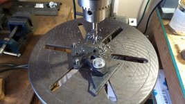
Upper Wing Mounts drilled today. Lots of fussing with alignments but made it all work. Since the first hole drilled will probably not align with the 3/16" pilot holes a machinist's trick is to drill the first hole with an end mill since it will not have a tendancy to follow existing drilled holes. Best to use some type of drilling guide. Follow up with progressively larger bits and then finally a ream. I mounted the 1/4" bit on a 9" extension by brazing. Always best to braze as it will uniformly keep the bit aligned with the extension, welding will tend to pull to one side as it cools and you will end up with a wobbly bit.

End Mill.jpg
 
That looks very professional. Did you put that together or are you "borrowing" it. An auto body shop about 25 miles away went out of business. It had a great paint booth. I talked to the bank that repossessed it about renting it for a couple months, couldn't work out a deal with them unfortunately.
 
Borrowing it, from my employer. :cool: Normally that booth is used for aerospace mil-spec whatever coatings. This Stewart's is probably the mildest stuff that booth has ever seen.
 
It’s not exactly on a Bearhawk, but it is in preparation of getting started. I’ve never done driven rivets before so I purchased a wing practice kit and the tool box kit from Vans. Today I completed the wing section for the first time. Tomorrow I’m going to begin the task of drilling every rivet out and redoing it. My plan is to do that 3-4 times then do the tool box. Hopefully by then I’ll feel confident in my riveting skills to do it for real. On my first attempt I’d give myself a C+. I definitely need work on double flush riveting. 88F590DB-C144-4EDE-86E3-AB4CDF35BCE2.jpg
 
Please examine the spar drwg sht. Double flush rivets under the strut attach fittings. Model 5 may be different. The thing with riveting, be bold, full blat. No tap,tap.
 
Last edited:
It will be harder and harder to get good looking rivets that don't tend to smear to one side or the other the more you remove and replace. Sometimes it is best to leave a non-perfect rivet alone rather than risk getting a much worse rivet the 2nd time. If you use a very small pilot bit to center drill the rivet like a number 52 (not very deep) it makes following up with a number 40 much easier.
 
You will get very god drilling out rivets. It's easy to get the drill bit back centered on the rivet. Its a quickly achieved skill set. soon you'll remove 100 out of 100 without a problem.

I see a rivet's shop head as smashed aluminum. We are smashing the tail of the rivet. We want the proper smash. Use some scrap stock....use it to experiment and have some fun..... try bucking rivets wrong. Using rivets that are too long and too short is educational. Experiment with Rivet tape. That stuff is a big time saver.

It is almost impossible to properly drive a rivet that is long....even slightly long is tough. The smash will drift off-center or the tail will tip over. Data suggest that a "slightly" poorly driven rivet still has almost all of its strength. I found that cutting rivets to length work hardens them and makes forming a good shop head far more difficult. So you need to get the Dash 3.5 and 4.5 length rivets that are available....and rivets are very cheep....drilling them out is consuming.

I have a copy in my workshop of Mil Spec Rivet Installation pdf. The generalities that are well published are fine. (like 0.5D thick x 1.5D diameter). But real specs are published and give you more lee way. Meaning a shop head that is not 0.5d x 1.5d may still comply with the engineering standards.
https://www.vansaircraft.com/wp-cont...-47196A_MI.pdf
 
Last edited:
I admit I sprayed ekoprime at home out in the open on my driveway (with a drop cloth). I didn't have any overspray issue. In the summer the primer dries very fast, I only did a few parts at a time, and I had a touch up gun dialed back a ways.
 
Last edited:
The rivets that are hardest to access are the most likely to get messed up in my experience. And if course it's those that are hardest to drill out... go figure!
 
Spinningwrench, since this it totally practice, I'm looking at the opportunity of drilling out the 100+ rivets as another form of practice since I'm positive I'm going to need that skill on my Bearhawk! I very well may end up upsizing the rivets when I do the rebuild. I am definitely going to keep your advice in mind when during the actual build.
 
Painting with a pretty broad brush. I have two quality digital levels (not Horror Freight) and they are very accurate. I'll calibrate them every so often, but they seem to hold their accuracy. But, that having been said, congratulations!

"The M-D Building Products SmartTool family is one of the pioneers in 360 degree angle measurement. Beginning in 1987, Wedge Innovations, invented, developed, manufactured, and marketed the custom liquid inclinometer used in the SmartLevel electronic digital level, sold through professional tool retailers worldwide. In 1992, Wedge was purchased by M-D Building Products, then Macklanburg-Duncan, a leader in contractor grade levels. For the last 25 years M-D has continued to grow the market for electronic angle measurement and is the market leader in this technology. Still the most accurate, affordable, inclinometer sensor in digital levels today, it is made in the M-D Building Products Headquarters in Oklahoma City, Oklahoma."
 
Today I installed these bad boys in place of the Goodyears. They're ABW 29's.
I then flew a bunch of circuits with them.

They make a huge difference to the landings, it feels like the suspension has doubled in it's "plush-ness". Also on landings I was able to hold the tailwheel off easier. One thing I did notice was a slight "grab" as the weight settled fully onto the wheels during landing. It felt like I was going through a puddle of standing water at about 30 kts. Not an issue, just an observation.

Take-off's, the immediate effect was that I can lift the tail off earlier and with less forward stick.
I haven't really checked the cruise speed out properly yet. I did briefly set 2200RPM, 22", and 37 LPH. It initially sat at 110 KIAS. I'll report further once I've flown a bit more with them.

56B935A1-2B50-42BF-A63B-04FD11428230.jpg
 
Those look great, what size were your prior tires? I'm starting out with Aero Classic 8.50s but plan on 29"BWs on another set of wheels for easy change over.
 
Previously I was on Goodyear 26" tires. These add 10lbs and move the CG from 8.3" to 8.2", negligible really. The improvement in handling is outstanding.
 
Yesterday I stopped working on the airframe, and I'm shifting to paint. Thats a big step for me, its all new and I'm apprehensive....That is common for me when starting a new task. My goal is to shoot paint before it gets too cold to paint here in Michigan (About 43 degrees north latitude)

Windshield, windshield fairing, left side window latch (which interacts with my throttle quadrant in my installation), and the Sky Light have all been nut plated and installed. Today I removed everything in preparation for paint.

IMG_4980.pngIMG_4981.png
 
Looks good! My experience on things like this is when you're done with them and even if they're not perfect, hey you're done with them! I wasted more time worrying about all kinds of things when I was building my RV-8 only to figure out later that all I had done was waste time worrying. I've finished priming the tail feathers and they will be the first thing I top coat.
 
I used a water level for leveling the fuselage on the roll axis (referenced main spar mounting brackets) and for dihedral ( with 2.9” offset at the wing tip per the build manual). Bubble level on lower longeron to level the fuselage on the pitch axis. Worked great!
 
All these airplanes on wheels, etc. very impressive and inspirational. Just wrapped up all 160 ribs for the Patrol and starting to get stuff done on stiffeners/moving on the wing spars. Did a quick jig to get the nose rib stiffeners laid out and a bushed phenolic drill jig to do the stiffeners. Delrin Bob sticks in the shot... def hold up better than any other material I've tried.

Click image for larger version  Name:	Nose_Rib_Stiffener_Jig2.jpg Views:	0 Size:	478.5 KB ID:	77145
 

Attachments

  • Nose_Rib_Stiffener_Jig2.jpg
    Nose_Rib_Stiffener_Jig2.jpg
    478.5 KB · Views: 0
Cowl doors cut and fitted, hinged. Ordered Cam-locs from Skybolt. Starting on fitting the intake portion of the baffling. Similar to Battson/Nev with an aluminum extension up to the inlet.
 
The first round of Fabric Coating application is completed. I built a temporary, functionally ugly paint booth uses 1" conduit, 4mil plastic sheeting, stapling to corners together. Filtered air is pulled through filters in the booth ceiling by two Box fans that sit on the floor of the booths side wall.

I feel very safe using Stewarts. The air system it requires is significant, but the breathing supply that I need to stay alive is simple....a charcoal filter mask. I have no experience painting. I ended up with no drips or runs. Slight orange peel is acceptable for me at my skill and experience level.

These are the Boulder Gray elevator, rudder, and gear legs.

IMG_5042.png
Screen Shot 2022-09-11 at 3.06.22 PM.png
The color is Insignia white with Boulder Gray trim on the tail feathers, tips and nose. The scheme is unimaginative. I want clean, simple and achievable. I designed about 60 schemes on a template from the plans and kept coming back to this one.

I hope the Boulder Gray will match the smoke gray windshield and side windows. A checkerboard or triangle rudder pattern for some zip and pizazz is not out of the question. I'm not sure N number size or location yet. 2 inch on the tail? Not sure if I have room for 12" behind the window. 12" on the stripe looks good.
 
Looking good Brooks, let me know of you need a vinyl paint mask for the numbers (or anything else). We can cut out squares for checkerboards too.
 
That looks great Brooks. One thing I found very important for getting a good paint job is lots and lots of lights. I twice ordered additional cheap led tubes to add additional light. I paint with the paint gun in one hand and an led trouble light in the other.
 
Jared;

I just sent you an email on the vinyl.

Rod; It's interesting what you found. In the photo I have one side lite with three of my lights. So far I am using six Harbor Freight 5500 lumen LED shop lights and am not sure three on each side are enough. Light behind me created the reflection needed to help see the amount of paint being applied by the gun. Without reflection, its guess work. I ended up doing what you did with one of those shop lights to focus and boost the light reflection. Managing the cords and the air hose took some effort. More can be learned in this arena to form an EAB Industry Best Practice I think.
 
Just stated the build and got the 5 fixed into the rotisserie today. I started a bit of the tail work too. Looking forward to the build!
 

Attachments

  • 20220921_175632.jpg
    20220921_175632.jpg
    1.5 MB · Views: 1
  • 20220921_175703.jpg
    20220921_175703.jpg
    1.7 MB · Views: 1
It's the parallel valve 540. Its last weighing was 1511 and the difference reflects removing lots of things.
 
Wrapping up the wing bits and pieces over the last three days in prep for starting the spars. Just entered 9th month of project... looking back on the build log, I started cutting aluminum sheet stock for ribs and spars on the 10th of March.

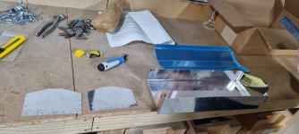
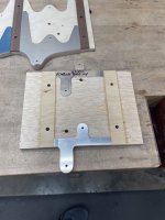
I do a lot of jig building for instrument work, so more of the same for the wing attach, spar join plates, and the filler pieces under the wing strut attach straps. And before someone says it - absolutely not worth it for four of each, but someone down the road will get some awesome tooling when I'm done. Not fond of routing small pieces of relatively thick aluminum or much of anything else, so most jigs I build for that job have a reference surface or two as well as two alignment pins, and are two or sometimes three sided to bring both size and mass up to gain controllability and to Murphy-proof.

Click image for larger version  Name:	IMG_3813.jpg Views:	0 Size:	2.06 MB ID:	77827
Spar join plates were ripped to width and the jig uses those parallel sides as reference for alignment and to beef up the alignment pins.

Click image for larger version  Name:	IMG_3813.jpg Views:	0 Size:	2.06 MB ID:	77827
Alignment pins hold things while the bottom cover goes on and help steady things once clamped up.
Click image for larger version  Name:	IMG_3813.jpg Views:	0 Size:	2.06 MB ID:	77827
Really small stuff gets a big piece of ply to better manage control of the work. I have a lot of 1/2" and 3/4" scrap sheet stock left from all that form and body mold building, so one way of using up stuff too good to send to the dump but too small for use elsewhere.

Click image for larger version  Name:	IMG_3813.jpg Views:	0 Size:	2.06 MB ID:	77827
The plan pattern for the filler strips under the strut attach straps is a little rough, so just easier to take a 4" wide piece of stock and flip end-for end at every pass... temporary stop and alignment blocks tacked to the tapering sled make this a quick job with a 7-1/4" aluminum blade. The filler pieces are about 0.9" wide at one end, and the saw kerf is 0.096", so little waste.

Click image for larger version  Name:	IMG_3813.jpg Views:	0 Size:	2.06 MB ID:	77827
Ready for edge clean-up, but that can wait until the fittings start going on the spars.

Other progress:

- I have a nice 19" bandsaw in the shop, but wanted to segregate the aluminum and steel chips. Picked up an ancient 4 speed Reliant from 1996 for about $200 (it had a very nice US-made 1 hp TEFC 56 frame motor, so worth it just for that). After brazing a cracked lower guide casting and the usual overhaul on guides, alignment, tires, link belt install, and building up a mobility base, I was out about a week of evenings, but had a pretty decent metal saw. Lowest speed is still too high for blade life cutting steel, but I have a couple sheaves that should do the trick.

- Still destroying steel tubing and flat stock doing the self-taught stuff for OA welding. Hope to get lined up with one of the EAA chapter OA weld gurus over the next month so that I can get the wing weldments (drives, hinge, etc.) knocked out by the time the spars are ready to go into the wing assembly jig.
 
Last edited:
Finished forming the last center rib tonight, full length tip ribs are all that left of the wing ribs. About 140 hours into my Companion scratch build. Loving every minute of it.
 

Attachments

  • CUXZ0654.jpg
    CUXZ0654.jpg
    1.9 MB · Views: 0
  • IMG_4053.jpg
    IMG_4053.jpg
    2.6 MB · Views: 0
  • IMG_4051.jpg
    IMG_4051.jpg
    2.1 MB · Views: 0
I have admirer. Went to reach for the drill and saw this little guy, turned out to be a black widow, and I am a total giant man-baby when it comes to spiders. Almost had to call my wife to come kill it.
 

Attachments

  • IMG_4127.jpg
    IMG_4127.jpg
    2 MB · Views: 0
  • IMG_4126.jpg
    IMG_4126.jpg
    841.6 KB · Views: 0
  • Like
Reactions: Nev
Last week I replaced the aft cargo bulkhead with one made from Kydex, and included an inspection port. It's yet to be tested inflight, but seems good, both functional and aesthetically clean. Weight was the same as the old one made from Corflute (corrugated plastic).

I also replaced the instrument panel coaming with a much larger rubber extrusion.


Click image for larger version  Name:	947A3EC5-646E-4143-9B2E-4F637738127A.jpg Views:	0 Size:	248.8 KB ID:	78044

Click image for larger version  Name:	947A3EC5-646E-4143-9B2E-4F637738127A.jpg Views:	0 Size:	248.8 KB ID:	78044
Click image for larger version  Name:	57C850C8-20BA-463B-97DA-EBD58ED75D39.jpg Views:	0 Size:	249.2 KB ID:	78045
 
Last edited:
Much like Robin, becky and I bought a Vans toolbox kit. Our BH kit (and tools!) are taking an obscene length of time getting to NZ, so this week we borrowed some tools from a friend to assemble the toolbox kit. Great way to keep ourselves occupied and get some experience driving rivets
 

Attachments

  • VideoCapture_20221007-215005.jpg
    VideoCapture_20221007-215005.jpg
    470.3 KB · Views: 0
  • 20221007_200734.jpg
    20221007_200734.jpg
    1.3 MB · Views: 0
  • 20221007_205317.jpg
    20221007_205317.jpg
    1.7 MB · Views: 0
  • 20221007_193537.jpg
    20221007_193537.jpg
    1.6 MB · Views: 0
Finished forming the last center rib tonight, full length tip ribs are all that left of the wing ribs. About 140 hours into my Companion scratch build. Loving every minute of it.

If I could offer a suggestion to those doing their own rib forming... make up a set of sample spars (2" to 3" long, full sized sections) for main, aft, aileron, and flap based on measured center/nose rib height after the first few ribs are 'done'. These make it a lot easier to tweak final fit of rib to spar and- especially when joggling - avoid letting things get out of hand. It also tells you when you have a big mismatch between formed ribs.

When I started making my center ribs, I realized the the final width at the main spar was highly dependent on whether I pressed or hammered the edge flanges (pressed ended up wider than flow-formed/hammered, likely due to the shift in bend location when using the VAF flange straightening tool) and whether the joggles were done after forming with a separate steel block or milled into the forming block and done with the rest of the flange work. I ended up with about 0.060" difference in height on the first few 032 and 025 center ribs post-joggling, so went back in and adjusted to maintain a good match at the main spar between nose and center rib height. Reworking always risks work-hardening, so best to identify fit issues early.

Those little spar sections are a quick ref tool for all that final tweaking, and also help when it comes time to bend up the real spars. If you bought the factory spar kit, just duplicate the sections with some 2" wide scrap... that will allow a quick look at how closely your rib forming process is to a good fit to factory spars.

Click image for larger version  Name:	IMG_3840 2.jpg Views:	0 Size:	281.8 KB ID:	78092
 
Last edited:
Since there is one chance to punch holes in the instrument panel I fabricated a trial instrument panel in plexiglass and mounted any devices that might have clearance issues. I am using a hinged electronics shelf behind the panel for mounting all the remote units. The Garmin G3X screen which pops out pretty easily along with the hinged electronics shelf should allow good access to any behind the panel wiring.

pic1.jpgpic4.jpgpic6.jpgpic7.jpg
 
Hoerner Wingtips Progress

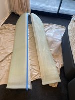
I've now made both tips, and did a trial fitting today. I was then able to drill the machine screw holes in place, and trim them to final size. Tonight I've epoxied the trailing edge after aligning it with the ailerons. Next is to apply a fairing cream, sand, and paint.


Click image for larger version  Name:	CBA731B1-C6F9-4504-A62C-0E8BA21EAA1D.jpg Views:	280 Size:	268.0 KB ID:	78103

Click image for larger version  Name:	1D802F1B-6504-4D3C-A802-9640D029B875.jpg Views:	273 Size:	346.2 KB ID:	78106


Click image for larger version  Name:	1D802F1B-6504-4D3C-A802-9640D029B875.jpg Views:	273 Size:	346.2 KB ID:	78106

Click image for larger version  Name:	1D802F1B-6504-4D3C-A802-9640D029B875.jpg Views:	273 Size:	346.2 KB ID:	78106

Update - finished and installed:

Click image for larger version  Name:	2CC9D37B-FB3D-4C8B-BDC6-E3C48E7F47F8.jpg Views:	0 Size:	193.2 KB ID:	78979

Click image for larger version  Name:	2ED78E5D-3C72-4074-B0BA-52364A2548EB.jpg Views:	0 Size:	272.6 KB ID:	78981
 
Last edited:
I'll do that Mark. I'll be assessing cruise speed and stall speed. I'll be pleased if there's a measurable difference.
 
Nicely done! How did you figure dimension / ratios? I think that's a good addition to the wingtip and will consider same with the Patrol
 
How did you figure dimension / ratios?

Actually Graham Johnson gets credit for that, including making and loaning me the ply ribs and Hotwire.
However the width is identical to the original wingtip, so nothing too scientific. Given that the original rounded tips don't contribute to lift, the upper wing surface is now theoretically increased by approximately 8" (the wingtip width) being that it is essentially flat. I assume that this translates to a reduction in wing loading, and possibly a reduction in stall speed. Theoretically the sloped undersurface should move the tip vortices off the wingtip, and keep the top surface unencumbered with a small reduction in drag. Perhaps those with a background in aerodynamics could add more to the story.​
 
Bent up a small section of aileron spar to check the fit all-around fit of the aileron nose/main ribs. It looks great and I'm super happy with how everything is fitting together. Being patient and working methodically has paid off.
 

Attachments

  • IMG_4157.jpg
    IMG_4157.jpg
    1.8 MB · Views: 0
  • IMG_4153.jpg
    IMG_4153.jpg
    2.1 MB · Views: 0
  • IMG_4159.jpg
    IMG_4159.jpg
    2 MB · Views: 0
My first time pulling a trigger on a paint gun was with this project. I painted the Fuselage this weekend. Insignia White with Boulder Gray trim. The wings will be white too. The boulder Gray parts will be the belly, rudder, elevator, wing tips, Flaps and Ailerons. I'm using Stewarts Systems. When you get close to this point in your build, I recommend a weekend covering seminar for the system you choose. I cant imagine covering without the Stewarts class. Additionally, my instructor continues to be a mentor and source for trouble shooting.

I recommend Jared for your paint masks.


Screen Shot 2022-10-11 at 3.13.14 PM.png
Screen Shot 2022-10-11 at 3.13.50 PM.png
 
Looks great! I've got to say that painting was my least favorite part of the process but, at the same time, it was the most satisfying.
 
Looks great Brooks! As a low experience painter, I had very good luck with Stewarts paint by following instructions exactly. I'm betting your mentor is Marty Feehan, he was a tremendous help to me in diagnosing my problems with metallic silver.
 
I also follow there guidance directly. I talked to Marty F. last week as I troubleshot a compressor moisture issue. John H. out of Wy. was my instructor and my mentor. These guys are Stewarts Tech support. I cant say enough good things.
 
I finished installing cowling Skybolt Dzus fasteners with the adjustable bases. I ended up attaching them with screws. Fairly easy to install. It all came out OK so far. I am not in love with the overlap of the cowl doors and the lower cowling sheetmetal at the forward corner. I may putting a little bend in the forward corner.
 
Looks good. Hard to see your trailing edge piece in the picture - whether the trailing edge has the pop rivets installed that Bob calls for on the plans. The trailing edges just come provisionally attached so you can adjust them if needed. Recently a builder covered without installing the correct pop rivets and it didn't go well. So thought I would mention it. Mark
 
Minor milestone: I finished up the plumbing for the main and aux tank in the right wing. I was a little puzzled about how to finish off the vent for the aux tank. I ended up bringing it outboard to the last bay, and then bringing it down to an under-wing vent (Cessna-style). I will have access to replace the under-wing segment (if it ever gets damaged) by removing the wing tip and reaching through the last rib.

Click image for larger version  Name:	IMG_0217 (2).jpg Views:	0 Size:	2.12 MB ID:	78872Click image for larger version  Name:	IMG_0218a.jpg Views:	0 Size:	2.40 MB ID:	78873
 
Trailing edge of ailerons and flaps all lined up with stretched string and pop riveted. I'll have to look in the hangar and see tomorrow if I used the 1/8" SS rivets Bob called for, I don't recall off hand if the holes were predrilled for 1/8" or 3/32" and possibly I used the smaller rivets.
 
One tip on fitting trailing edges from my old biplane days, put a small ball of thickened epoxy adhesive where the inside of the t.e. and the end of the rib fit together. Pop rivets can and do get loose from vibration, fabric tension and age allowing the t.e. to shift fwd leaving an annoying wrinkle in the covering just fwd of the t.e. The cured epoxy keeps the t.e. and the rib intersection stable. Keep the epoxy balls small so there is little weight to counterbalance on the ailerons.
Gerry
Patrol #30
 
Last edited:
IMG_0013.jpgYHAP8364.jpgIMG_4082.jpgIMG_4419.jpg
This is my version of Horner tips 4 pieces of 2 in foam cut to the wing rib template .750 alum on a table router then stacked together with 1 in alum rod then used a hot wire to cut along the template and another template for the outer end. Sanded the mold to final shape, then prepped 2 layers of carbon fiber and one layer of fiberglass layed it over the styrofoam mold sitting on the template and vacuum bagged the complete tip to an old solid core door as a base. Tried to upload some more pics but its an Iphone and they are HEIC files.
 
Last edited:
Svyolo…. Welcome to KAWO. Where are you on the field. I am also at Arlington. I am on the NE end just behind Eviation. I am there most days. I built an office in the back corner of my hangar that I telecommute from. You aren’t sharing a hangar with Fisel by any chance? We should meet up. I am building a patrol. I bought a quick build fuselage from mark and have scratch built the wings.
 
Last edited:
That seems so easy to do. Now that I see the pictures. I am willing to bet there is a pile of work involved in what you are building to layup wing tips.
 
Back
Top