
You are using an out of date browser. It may not display this or other websites correctly.
You should upgrade or use an alternative browser.
You should upgrade or use an alternative browser.
Tell us what you did today on your Bearhawk Project
- Thread starter Bcone1381
- Start date

Bcone1381
Finished Patrol
The fuel flow test is complete and unusable fuel check was performed last week. I did a battery capacity check today and installed the Tanis Engine pre-heater. My next big goal is installing everything like cowl, fairings and what not, put the aircraft on scales. I'll also be doing a flow test on the fuel injectors. I think I'll have everything ready to download onto the FAA's portal for their inspection.

svyolo
Junior Member
Thanks, and thanks to everybody on the forum that made this possible. I would not have even attempted it if I hadn't known it existed. Special thanks to those with successfully flying BH's that continue to contribute, Mark for great customer support, and maybe the unsung hero who keeps this forum going, Jared. I did 3+ hours of training last month which with Jared which was invaluable. Highly recommended and Jared is a great instructor.

Redneckmech
BH Five Scratch Build
Congratulations! Now it is time to enjoy flying it!

alaskabearhawk
Moderator
That is fantastic....congratulations! I can't wait to see some pics and get a PIREP.

DBeaulieu
Patrol Q/B Kit #79
Nearly complete with fabricating engine stand for the airplane engine (Lycoming YI0-360) - plan is to put factory firewall, engine mount and engine on the stand and be able to work on it in a comfortable heated garage. Might even be practicable to start fabricating the cowl after I dress the engine? Built with material I had around, except for the 1/4" plate I had to buy (ouch). It seems to be plenty beefy and very stable for storage and moving around the shop.


rkennell
Companion QB

 DBeaulieu I did something similar and have found it very useful to prep the engine before installing on the air-frame. I used scrap lumber I had around the farmstead and bought some casters. If I was doing it again I would raise the engine a little higher. It sure helps to be able to move the engine around. I like your clean design.
Attachments

DBeaulieu
Patrol Q/B Kit #79
Finished engine stand today and mounted firewall and engine mount. I plan on mounting the engine next weekend. Anyone with good info on hardware and proper install technique of the engine isolators, let me hear y'all! I've got the Patrol kit dynafocal type 1 engine mount and the Lord J7402-16 isolators. 
Cheers, (Dave from Maine)
Cheers, (Dave from Maine)
DBeaulieu
Patrol Q/B Kit #79
Got the engine out of the unheated hangar and brought it "home" for the winter to a nice climate controlled garage. Got it mounted to the engine stand and was pleasantly surprised that the engine mounted right up to the dynafocal without fuss. Now I can figure out what I've got to do to get it ready for use! 


alaskabearhawk
Moderator
Congratulations!!! Can't hide from ADS-B.

Bcone1381
Finished Patrol
My Patrol was put on scales earler this week. 1190lbs, 10.3" It will require effort to fly it aft of CG like this. 10.5" is the forward limit, and when I get in it with an hour of fuel I'm at 11.0".
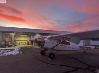
Yesterday Arborite and I did the first engine start. I have dual Surefly Mags. Arborite has a history in hobby auto racing, and a long time general aviation background. (He has an LSA under construction). I mean to emphasize that he knows engines and has lots of experience with various ignitions, and magnetos. He was impressed with the ease my first start. With the throttle cracked, mixture lean, zero Fuel Pump instigated prime, he and swears it lite off on the first blade! We seemed to have stumbled upon .....learned ....that the Bearhawk's gravity fuel system is sufficient to prime the engine thru the Bendix FI servo.
Yesterday Arborite and I did the first engine start. I have dual Surefly Mags. Arborite has a history in hobby auto racing, and a long time general aviation background. (He has an LSA under construction). I mean to emphasize that he knows engines and has lots of experience with various ignitions, and magnetos. He was impressed with the ease my first start. With the throttle cracked, mixture lean, zero Fuel Pump instigated prime, he and swears it lite off on the first blade! We seemed to have stumbled upon .....learned ....that the Bearhawk's gravity fuel system is sufficient to prime the engine thru the Bendix FI servo.


rodsmith
Well-known member
Just got home from visiting Virgil's facility in Fairview, OK. A long drive but worth it to get a checkout from Virgil in his Model 5 before first flight in my 4. My preparation for first flight started with a Flight review in a Citabria in Camas, WA to get legal, while visiting my daughter in Portland over Thanksgiving. I have been getting instruction at my home field in a 4 seat Taylorcraft with an O-470. If you have never heard of a 4 seat Taylorcraft, neither had I until a neighbor bought it a year ago for glider towing. I planned to fly my first flights off the alfalfa field next to our runway, so of course when I get home there is now 3"s of snow on it and the weather looks awful for the next week. I have to admit to some "5" envy after flying Virgil's, the 5 is an amazing airplane. My plane actually has more horsepower and weighs a little less. After accounting for our elevation at 6400', should be about the same power to weight ratio. Virgil has a great facility. I saw some new parts, an aluminum plate to mount the rudder and elevator servos at the tail and a tray for the ELT. Virgil is testing Catto constant speed propellers. There was one on his 5.


Astro John
Well-known member
The Catto prop sure looks good!


spinningwrench
Patrol

Heavy current sub-panel done. Tomorrow should wrap up all wiring.

Dpearson
4-Place QB (A Model)
Major milestone (for me at least): today is the first time any part of my Bearhawk has seen electricity. I hooked up a current-limited power supply at the wing root connector of each wing to test the transfer pumps. They sounded like electric fuel pumps without any fuel in them. Success!
With that last "wing" task checked off, it's time to rivet the top skins down.
With that last "wing" task checked off, it's time to rivet the top skins down.


Chewie
Well-known member

svyolo
Junior Member
N776BE up to 36.6 hours. I should hit 40 in the next couple of days and then take 3 months off to warmer climates. I may not call Phase 1 complete until I do a mod to #6 baffle to fix a warm cylinder, and adjust the prop gov arm as I can only get 2520 rpm. Too cold in the hangar to do that much work for now.
Landings are coming along. Engine runs great and doesn't leak (yet). It flies hands off, after I learned the difference between "heavy wing" and a rolling moment. Writeup on that in the net couple of weeks along with some other stuff.
Landings are coming along. Engine runs great and doesn't leak (yet). It flies hands off, after I learned the difference between "heavy wing" and a rolling moment. Writeup on that in the net couple of weeks along with some other stuff.
rkennell
Companion QB
After moving 40 years of old parts and junk, then a lot of cleaning, putting up new lights and installing a new heater I moved the airplane into the old farm shop that dad and I build in 1976 
 After moving, I worked on skinning doors and working on windows.
 The brakes and parking brake have been permanently been installed, along with the fuel system in the cockpit and fuel lines to the firewall.
I

 Different items like the injectors, alternator, backup generator, ignition coils, hall sensors, and flywheel magnets
 have also been installed on the engine.
When I look back through the photos I can tell that progress has been made. I am very grateful to this forum and the fellow builders in this area for the help they have offered. Dean who has worked as an avionic tech and is building his second airplane, has been designing the electrical system and has helped me with sheet metal work, Keith who is an AI and restored several airplane has provide encouragement and given instruction on many skills such as safety wiring and riveting and continues to inspect my work and advise. This project has been a fun journey.
After moving, I worked on skinning doors and working on windows. The brakes and parking brake have been permanently been installed, along with the fuel system in the cockpit and fuel lines to the firewall.I
Different items like the injectors, alternator, backup generator, ignition coils, hall sensors, and flywheel magnets have also been installed on the engine.When I look back through the photos I can tell that progress has been made. I am very grateful to this forum and the fellow builders in this area for the help they have offered. Dean who has worked as an avionic tech and is building his second airplane, has been designing the electrical system and has helped me with sheet metal work, Keith who is an AI and restored several airplane has provide encouragement and given instruction on many skills such as safety wiring and riveting and continues to inspect my work and advise. This project has been a fun journey.
Last edited:


Gerhard Rieger
Well-known member


DBeaulieu
Patrol Q/B Kit #79
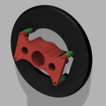
Got the EZ heat pad install on my sump finished up. My hat is off to alaskabearhawk who was able to do his EZ heat install with the engine and plane all put together and do a video at the same time !




huntaero
4 Pl BHK scratch build
Made a spacer from plywood bolted it to the crank and screwed another piece of plywood to clamp it in place using wood screws. mounted the firewall behind the engine mount on a rotiserie so i could rotate the assy. Could be mounted on the fuselage also then join them together.
Attachments

Last edited:
DBeaulieu
Patrol Q/B Kit #79
Tried this technique in an attempt to work some more on baffle fitment and possibly a cowling fabrication. Leveled (horizontally) the top engine mount braces and the split line of the nose bowl and worked on getting good symmetry of the spinner to the nose bowl. Top U-channel pieces are placed with 12" spacing and cut generously for final trimming. Where can I go from here...if anywhere? I can measure for making a jig to hold the nose bowl correct distance from spinner back plate (by referencing the crank flange?) That would allow me to pull the prop and get that out of my way. Still mulling things over - open for suggestions! All input appreciated! Cheers Dave
 .
.
Have decided to go with making a jig setup so I can remove the prop and have a very secure nose bowl attachment during fit up and cowl fabrication. Used the Bearhawk 3D print file to print out the spacer. Worked out great with my MTV-15 2B Ultra prop hub.

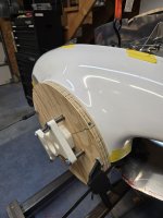
.Have decided to go with making a jig setup so I can remove the prop and have a very secure nose bowl attachment during fit up and cowl fabrication. Used the Bearhawk 3D print file to print out the spacer. Worked out great with my MTV-15 2B Ultra prop hub.
Last edited:
rkennell
Companion QB
Since moving into the farm shop, the wings have remained in the cradle with most of the wiring and plumbing done. My attention has turned to the fuselage which I put on a rotisseries. I removed the landing gears and temporarily reinstalled the tall feathers to facilitate the installation of the yaw and electric trim servos. I am going through a learning curve on how bend metal. Follow builder Dean has been very helpful giving pointers and advice. He has also been designing the electrical system and we have had many discussion about panel design. Both the of the designs have stabilized and only require final tweaking. Today, I finally finished the bracket for the yaw servo and mounted it. tomorrow it will be getting the seervo connected to the rudder horn.
The first photos are of the electric trim and the amount of travel I have.


These are of the yaw servo.


Early drawing for the electrical system and panel.


Work is progressing.
The first photos are of the electric trim and the amount of travel I have.
These are of the yaw servo.
Early drawing for the electrical system and panel.
Work is progressing.
Bcone1381
Finished Patrol
Hey Roger, Good to see you making progress!!
A data point on your electrical system drawing. You say Its an "early drawing." Great to share it with us! A classic quote from the link below on failure tolerance (P.2 second column) "Remember we are striving to design failure tolerant systems and pilots to go with them..." That means the goal is if one electrical system component fails, nothing scary happens. Some of us look over diagrams for scary single point failure modes. I see one.
http://www.aeroelectric.com/articles/failtoll.pdf

A data point on your electrical system drawing. You say Its an "early drawing." Great to share it with us! A classic quote from the link below on failure tolerance (P.2 second column) "Remember we are striving to design failure tolerant systems and pilots to go with them..." That means the goal is if one electrical system component fails, nothing scary happens. Some of us look over diagrams for scary single point failure modes. I see one.
http://www.aeroelectric.com/articles/failtoll.pdf
rkennell
Companion QB
That is a good and helpful point Brooks. Thanks. We are having the system reviewed by several people. Dean and I are in discussion as to what needs to be done to eliminate a single point failure situation. For this system it is critical because of its reliance on electrical power to keep the engine running. Thanks.


svyolo
Junior Member
I haven't tried that combo for anything. I might give it a try. I would have guessed two layers of carbon with Kevlar as the core.
I made one attempt at a floorboard using foam core, without vacuum bagging. I will probably try again in the next couple of months with a V bag.
I made one attempt at a floorboard using foam core, without vacuum bagging. I will probably try again in the next couple of months with a V bag.
Gerhard Rieger
Well-known member
Traditional Hoerner wingtip 22” made of alclad 2024/T3. I still have to finish the leading edges, fit the landing lights and nav lights.
Attachments


U2fletch
Well-known member
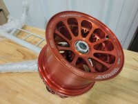
Waiting on hangar floor to get epoxied before we completely unbox our QB BH5 kit #56. In the meantime I decided to see how the Beringer wheels/brakes work. The brake calipers are fixed, and the disk floats, which is interesting, and the calipers are inside the disk! These are the 10" wheels.

The kit includes an aluminum spacer, which sets the caliper to bearing distance. This spacer is 1.5" inner diameter, so does not fit over the portion of tubing next to the flange where you bolt everything together. Also, that tube is a little too short, (0.154") to get the correct spacing without the Beringer part so I chucked it in the lathe and removed 0.062" with a boring bar. and left a small lip inside to face the bearing.
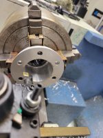
A quick trial fit and I was relieved to find that there is just barely enough thread on the axle for the retaining nut and cotter pin.

29" Dessers will go on the wheels, so think it will work fine.

The kit includes an aluminum spacer, which sets the caliper to bearing distance. This spacer is 1.5" inner diameter, so does not fit over the portion of tubing next to the flange where you bolt everything together. Also, that tube is a little too short, (0.154") to get the correct spacing without the Beringer part so I chucked it in the lathe and removed 0.062" with a boring bar. and left a small lip inside to face the bearing.
A quick trial fit and I was relieved to find that there is just barely enough thread on the axle for the retaining nut and cotter pin.
29" Dessers will go on the wheels, so think it will work fine.
Attachments



spinningwrench
Patrol
I sent you a plywood scheme to pull this off, did you not get it?
Gerhard Rieger
Well-known member
Satisfying to stand back and to take a look at a finished wing, great job


brady.blake55
Member
Today was the first day I actually did anything in the garage other than get the shop setup. I completed my master rib form block and 2 nose rib form blocks. Pit 2 coats of wood Gardner on all of them. Basically, I just hung out in the shop and tinkered. I’m supposed to get my aluminum in another week so I’m fairly limited on what I can do. I was able to get 4x12 sheets of .020 for $144 and .025 for $163. Factoring in not having to pay for shipping, it was quite a bit cheaper than Aircraft Spruce or Wicks. And it won’t be rolled so I don’t have to deal with that.
I find myself constantly buying tools because “I might need them” for the build. Today I bought the metal cutter that hooks to my drill. TikTok shop, Harbor Freight, and Whatnot are not good for my budget.
I find myself constantly buying tools because “I might need them” for the build. Today I bought the metal cutter that hooks to my drill. TikTok shop, Harbor Freight, and Whatnot are not good for my budget.
rkennell
Companion QB
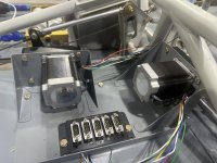
I have finished installing and connecting all three auto pilot servos to the controls. The network and electrical connections need to be made yet. The beacon bracket has also been fabricated and installed. The bracket to raise the bolt attachment on the bank servo was Dean's idea and solved a clearance problem between the fender washer and the cabin floor when the stick was rotated all the way back.



We have also had the panel laser cut and will soon start installing some of the avionics. The electrical system design has been finalized, incorporating suggestions that Brooks and others have made.

We have also had the panel laser cut and will soon start installing some of the avionics. The electrical system design has been finalized, incorporating suggestions that Brooks and others have made.
brady.blake55
Member


What did I do today? Made a bunch of forming blocks. Then tipped a “table” of MDF, my plans, and a huge Stanley full of my kegged Topo Chico. Don’t worry, my plans kept the floor of the garage nice and dry.
Let’s hope they dry without wrinkling up.
I wonder if this is what happened to the Ford Trimotor? Started out straight, plans got wrinkled, then the whole plane got wrinkled.
In our shop we found that if we don't have big inspection plate holes, we need smaller hands.
Attachments

spinningwrench
Patrol

 Fabric fully on. This little “shoe” on my small fabric iron made attaching the fabric in the window channel go really well.
 These are for the wing root fairings...only 68 to put in for both wings. That's less than one fuel tank bay!
Dpearson
4-Place QB (A Model)
At long last, I have both wings all closed up and ready to move to storage. That'll make room for the fuselage in the garage. I'll be starting by surveying the work done by the previous builder. It's on the gear with doors on and flight controls partially rigged, firewall in place and what looks like a reasonable start on the boot cowl. No wiring and thankfully no fabric on it. It's got the original streamline-style gear struts, assembled probably 15 years ago. Not sure if there's any oil in them but I'll probably take them apart and install fresh seals (already purchased from Bob). 3 years into the 3 year project, with 3 years to go I think!

rkennell
Companion QB


DBeaulieu
Patrol Q/B Kit #79
Getting wing interior work done. Pitot tube stuff, wiring, etc. Got a July date with the paint shop to get the wing paint on, so I need to get the wings riveted up soon! Need to add an access panel on the wing for the pitot heat controller access, and on the other wing get the roll servo setup and installed.


DBeaulieu
Patrol Q/B Kit #79
While pondering fuel tank cover issue, decided to go ahead and make cutouts for the wing lights. Have Flyled Taildragger Max lights for each wing. Also decided to go with brass barbs and 3/8" rubber fuel line hose from the tank outlets to the fuel line beaded tubes at wing root / fuselage connection. Will keep1/4" tubing and AN fittings for feeds to the fuel quantity sight gauge circuit.


Last edited:
U2fletch
Well-known member
I am a Ham radio guy, so when I saw this style of dipole antenna bonded into the fuselage of our Sportsman, I wanted to see if they would work in the Bearhawk. These are suitable to use in a tube/fabric aircraft. Try to keep them away from metal, but tubes crossing nearby at a 90 degree angle are okay, and the antenna shoud be within 45 degrees of vertical for proper polarization. I used fiberglass shafts from Goodwinds, and 3d printed mounting bits to attach to the stringers. Right now, they are just held on with zip ties. I will take some of my antenna SWR testing equipment out to the hangar and move the fuselage into the open for some real world testing using a handheld radio plugged into the BNC cable. 
Dpearson
4-Place QB (A Model)
Working my way through the main gear on my 20-year old kit. Disassembled struts and replaced the o-rings with fresh ones (purchased directly from Bob).

Previous builder had run hard line from the gear leg directly to the caliper via the shortest possible path, leaving no extra loop to absorb caliper movement. I've decided to terminate the hard line inside the gear leg and transition to a flexible line where the fitting will exit the fabric. Work in progress.


Finally, I found that the 4AN fittings at the top of the gear legs had "goop" on them which felt and smelled like EZ-Turn. My understanding is that these flare fittings should be assembled clean and dry. After an acetone bath and scrubbing with a nylon brush they are all clean and seem usable. I've ordered up some Loctite 567 and will be using that to re-do the NPT side of the adapter fittings on the calipers, in case EZ-Turn was used as a "sealant" on those joints.
Previous builder had run hard line from the gear leg directly to the caliper via the shortest possible path, leaving no extra loop to absorb caliper movement. I've decided to terminate the hard line inside the gear leg and transition to a flexible line where the fitting will exit the fabric. Work in progress.
Finally, I found that the 4AN fittings at the top of the gear legs had "goop" on them which felt and smelled like EZ-Turn. My understanding is that these flare fittings should be assembled clean and dry. After an acetone bath and scrubbing with a nylon brush they are all clean and seem usable. I've ordered up some Loctite 567 and will be using that to re-do the NPT side of the adapter fittings on the calipers, in case EZ-Turn was used as a "sealant" on those joints.
Attachments


Gerhard Rieger
Well-known member
Right wing ready for topcoat paint, left wing on the table to makeup fuel filler covers 


rkennell
Companion QB


 With the Nav antenna installed, all the wires, static, pitot, AOA tubes are in the boot cowl area. I have constructed the primary power distribution panel and assembled the breaker panels. The panel has been powder coated and the vinyl overlay with the labeling is being printed. I have been working on laying out the of the different avionic components and once the panel is finished, I will start making harness and terminating wires.


Attachments

Dpearson
4-Place QB (A Model)
Working through first builder’s rudder rigging. The rudder pedals seem to have been mounted too far aft (5” behind centerline of firewall station). With this condition it’s impossible to depress the brake pedal with the rudder pedal at its forward-most travel. Unbolting the pedal assembly and clamping it as far forward on the support plates as possible seems to correct the geometry and result in good brake behavior.
Before:

After:

Before:
After:
DBeaulieu
Patrol Q/B Kit #79
Started riveting up the wing skin on my left wing. Think I've got the A/P roll servo figured out on the right wing. Using a base plate from Virgil to prototype in the Patrol along with a Dynon servo wing mount for an RV-6. The servo is the Dynon SV-42 with the extra long control arm which allows for 4.4" of total linear travel according to the spec sheet. Moved the base plate toward the forward wing spar to allow clearance of the control arm to clear the support frame tube of the aileron drive assembly. Base plate required notching on one side to clear wing stiffener.


U2fletch
Well-known member
Here is the A/P roll servo mounted in our wing. Similar idea using a plate riveted to the ribs. The pushrod is bolted just below the aileron pushrod. Checking the aileron travel throws at the bellcrank shows only 1" cable each way from center required for full deflection.


DBeaulieu
Patrol Q/B Kit #79
Slow going, but making progress on closing up the left wing. Was thinking I could squeeze all the wing to pocket skin rivets, but can only squeeze the top skin to pocket skin due to curvature of the pocket skins. The bottom wing skin had to be bucked. Hope I never have to drill out any of the CCP42 rivets called out in the wing manual for the pocket skin to rib fasteners. Also got my pitot mount mostly riveted in. Have two problem rivets that seem to defy proper setting...not sure what's going on. Will reassess another day when fresh.


DBeaulieu
Patrol Q/B Kit #79
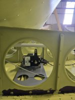
Finally finished up the left wing except for a couple "problem" rivets...waiting on a more experienced sheet metal friend to give it a look. There are quite a few more rivets than I was expecting when estimating how long it would take to completely rivet up a wing! Got the AP servo assembly painted, installed and wired on the right wing. Should have the right wing riveted up over the weekend and into the paint shop by end of the month! 


fairchild1934
Well-known member
laying out horizonal stab drawing on build table. making a bending for for the LE tubing out of 2 pieces of hard wood ply wood. About to make the little towers to support tubes 1 inch off of table.
