mswain
4 Plc Mostly Scratch Bldr
I wanted Hoerner style wingtips, primarily because I like the way they look, but there are some purported performance advantages over rounded. The Hoerner shape also lends itself to housing the Bob Archer style VOR (Not even sure VOR will be around when I finish) antennas I made and it will allow me to mount my lights under a lens.
Stuff You'll Need:
MDF to make 2 full size airfoil forms
Enough foam to make 2 wingtips the thickness you require
Fiberglass Cloth & Resin (Epoxy or Vinylester)
QuickFair or filler of your making
Lightweight spackle or Polyurethance+Microballoons
Sandpaper - I suggest 80 - 120 - 220
Nichrome wire - 22 gauge
Foil Tape, min 1.5 inch wide
Power source for hotwire - Battery Charger, etc.
High Build Primer
Make the Forms:
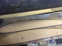
To start, I rough cut a piece of MDF and set it up against the outboard edge of my wing and traced the airfoil with a sharpie. I cut to the line using a band saw and jig saw. I then used a random orbital sander to finish until the line was just gone.
My plan was to mount the tips flush, not overlap....so I reduced the form by another .0625" to allow for the fiberglass layup thickness. I drew a line .0625 in from the edge by using a scrap piece of aluminum the correct thickness and dragging it around the form with a sharpie. I then sanded the form down to the new line. Because I need two identical forms to hotwire the foam, I traced the completed form onto another piece of MDF and rough cut. Using a few screws, I screwed the two pieces of MDF together and used a flush cut router bit to make an exact copy of the first form.
The two forms will sandwich the foam and the hotwire will glide along the forms resulting in a airfoil shaped block of foam. The two forms need to be exactly in line with each other during this process. I am sure there are many ways to ensure the forms are inline, but I simply match drilled the forms with a couple of 3/8 guide holes while the forms were screwed together which threaded rod will go through later in the process.
I made my wingtips 10" wide, primarily because a single 4'x8' sheet of 2" foam supplied enough material. But you can make them any width you want, just glue together enough foam.
Using a framing square, I laid out lines on my workbench to match the distance between the 3/8 guide holes in the forms. The width of my wingtips are 10", so the layout is 10" + 1.5" to account for the 2 MDF forms. I then made 4 supports from some scrap 1x2, 2 for the front and 2 for the rear. The pairs were match drilled and long enough to suspend the forms and foam in the air over my bench. I drilled the 4 supports with a Kreg jig I use for wood joinery, but it's perfect for attaching wood at right angles. You'll also want to ensure the ends mounting down to your work surface are square, I cut mine using a chop saw.
Prepare the Foam:
I used one of the airfoil forms to trace the airfoil 5 times on my 4'x8' sheet of 2" thick polystyrene foam I picked up at Home Depot. I also drilled the foam through the 3/8 guide holes while I was tracing the airfoil.
I rough cut the sheet into 5 pieces using the tracings in the previous step. I used an old hand saw I had laying around.
The foam I purchased had foil on 1 side and plastic on the other. I peeled this off so i could glue the 2" pieces together to get 10" total. I used 3M 78, which is a FOAM safe spray adhesive. If you use a different glue, test it on some scrap foam.....because many of the solvents in glue will eat polystyrene, especially the spray adhesives.
To glue everything together, I ran 2 threaded rods up through the guide holes on one of the forms so the rods were sticking up in the air. I slipped the first piece of foam down over the rods then sprayed the inside end with adhesive along with the subsequent joining end of the next piece. Rinse and repeat until you get to the last piece. You don't want adhesive on the outside ends between the forms and foam, we just want to glue the pieces of foam together to get our desired thickness. I slipped the second form onto the rods and snugged the whole assembly together while the adhesive dried. I went for tight but I didn't want to crush the foam.
Hotwire:
Once the adhesive is set, you are ready to hotwire. I set up the assembly using the 4 supports screwed down to my workbench, so the forms and foam are suspended over my bench.
I made a hotwire tool with a scrap piece of 1x2 and some scrap fuel strap (.025 4130 bent at 90 degrees) It needs to be wide enough for the width of wingtip you are building. You want the wire to glide along the two MDF forms. The Nichrome wire I purchased from Amazon. the wire needs to be as tight as possible.
For a power source I used a car charger. It seems the newer digital chargers are smarter than the old dumb transformer types, so I used an old 12V UPS battery to trick my charger into putting out the juice.
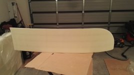
Once you have your hotwire tool ready, it's time to cut some foam. the idea is to have the wire glide along the top of your forms at a nice slow steady pace. Not too fast to drag the wire, but not too slow where you burn excessive foam. You can fix most imperfections when you fill the foam, but try to get a clean cut. Do one side, then flip the whole assembly in your supports and do the other side. Take it out of the fixture and you now have an airfoil shaped chunk of foam the thickness of your planned wingtip.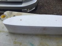
Now we will create the Hoerner shape. To do this, we will apply foil tape along the edge of the foam for the hotwire to ride on. On the lower inboard side of the wingtip, I made a line 1 inch from the edge. I carried this to about the center of the front of the airfoil. Now on the TOP of the OUTBOARD edge of the airfoil, I came down about .25" inch from the edge. There is nothing hard and fast about .25. but this will determine the thickness of the outboard edge of the wingtip. If you want thicker, make the dimension bigger.

To hotwire this, I plunged the hotwire into the foam until just making contact with the foil tape, then gently drug the wire trying my best to keep the wire square for a nice even pull. The video shows this in more detail.
Now you've got a funny looking airfoil-hoerner sculpture. The next step is to put the front radius on. From this point on it's more up to you and how you want the final shape to be. I followed the convention outlined in the video (https://youtu.be/RoOh-fgI8oU) which is to use the width of the wingtip as the radius of the front curve, 10" in my case. I am happy with the look and the way it came out. I used a piece of safety wire around a sharpie to draw the 10" radius from the front inboard edge of the airfoil to outside edge. I then used my hotwire tool held vertical to the foam
and rough cut the radius.
Prepare the Form:
You will end up with a blunt edge on the front of the airfoil where you cut the radius. Use a rough file or rasp to blend this blunt edge into the existing airfoil. I went ahead and ever so slightly radiused the outboard edge of the wingtip to the point where the airfoil is the thickest. Seems to be about 1/3 of the way back from the front. This was done by eyeball until I got a pleasing shape.
I then used some 80 grit sandpaper to rough sand any ripples from hotwire and generally level the foam. I used some 120 to put a nice radius on the outboard edge of the wingtip. You don't want any sharp edges since fiberglass will pull away if you try to layup over a sharper corner.
I then used some lightweight spackle to go over the form. sand. fill. sand. fill. You want a nice smooth surface to layup over. Any imperfection will transfer into the fiberglass. I read in the Bingelis book that Polyurethane mixed with Microballoons makes a good mix to cover foam forms. I had already used spackle before I found that tidbit, but you might want to explore that method. You'll want to make sure the entire form is covered, because paint and certain resins will eat foam.
After getting things as smooth as possible, I put a couple of coats of rattle can spray paint. I used orange because I wanted to be able to see the form as I was laying up, to make sure there were no air bubbles.
To prep for layup, I waxed the painted form with 4 coats of good carnuba car wax I had in the garage. I then sprayed 3 coats of PVA.
Layup the Fiberglass:
My layup schedule was 4 layers of 8.8 oz Bi-directional cloth from Spruce. (01-00642) There was no science in that choice, just a guess. They seem to be pretty sturdy and came out around 7 lbs. each.
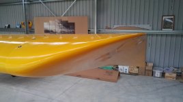
I used System 3 Silver Tip Epoxy as my laminating resin. It is a popular choice among home boat-builders. No amine blush and simple 2:1 mix ratio. It can also be post-cured at higher temps to improve the structural properties, which is a bonus for room-temp cured epoxies. Make sure your foam is 100% protected if you use Polyester or some other non-foam safe resin.....or all that hard work will melt away.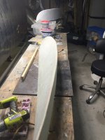
Attach the Wingtips:
I will not go into detail on attachment, but I ended up using piano hinges. I didn't want to have to undo a bunch of screws every year at annual. I followed the steps the RV guys have outlined. The only exception is I built an access panel on the top of the wingtip to access the hinge pins, since the Bearhawk's tip rib extends all the way back, unlike the RV method of securing the hinge pins.
I followed this method: [FONT=Verdana, Arial, Helvetica, sans-serif]http://websites.expercraft.com/n51pw...y&log_id=23961[/FONT]
I used .040 strip of 2024 as my spacer, since there is no cutting of these wingtips. Also, since there is no gelcoat on my homebuilt wingtips, they were translucent enough for me to mark the hinge and drill based on marking on the hinge.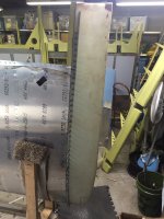
Fair the Wingtip:
Once I had the wingtip mounted, I used Quick Fair (a commercial fairing compound) to level and get a nice surface on the wingtips. This requires several thin coats and lots of sanding. I use a 3M semi-flexible longboard. 80 grit for rough, then 120, then 220. Depending on the quality of finish you want will determine how much time is spent here.
Prime:
I applied high build epoxy primer next, sanding between coats.....until i get a perfect surface. Once you are happy, they are ready to be painted or further modified for lights, etc.
LENS:
First, I needed the shape of the lens. To know how big I wanted, I made some cutouts of poster board to represent the size of my landing light and nav/strobe. I used these to determine how far back to go so I would end up with enough mounting area for the lights. Once I had this I drew the cut lines on the wingtip. Keep in mind your position lights (red & green) are supposed to be visible 110 degrees.
Once I had the wingtip marked up with a fine sharpie, I used a Dremel cutoff wheel to carefully cut the lines, but I left small uncut areas in the corners so the piece we want to remove stays securely in place for the next step, which is making the lens mounting flanges.
I marked parallel lines to the cut lines on the inside of the wingtip, 3/4" inside and 1.25" outside. The idea is to have 1/2" flanges after trimming and the 1.25 overlap outside gives good bonding area to the inside of the wingtip. I cleaned the area inside the cut lines with air then wiped with solvent to clean any dust from cutting. Next I used clear packing tape to cover the entire area inside the cut lines, this will prevent the fiberglass from bonding.
I now cut some fiberglass cloth so it would span the lines marked previously. It should protrude about 3/4 inch into the area where the lens will be and 1.25 outside the line where it will bond to the wingtip. I ended up using 4 pieces to go all the way around, I found it eaiser to work with multiple pieces. Once I had the glass cloth shapes cut, I made 6 more of each shape for a total of 7 layers. I scuffed up the area outside the cut line where there is no tape (careful not to move or mess up the tape) then cleaned with some alcohol. For the flanges, I wet out the cloth on a piece of parchment paper then put it in place, lining it up with the lines previously marked.
Once your flanges have cured, you can carefully cut the rest of the lens area out. Be careful not to cut beyond the thickness of the wingtip, you don't want to get into you new flanges. Once you've removed the material you should be able to work the piece free since the cloth will not bond to the packing tape underneath. Be careful not to damage the cutout, as it will be the form for your lens. Now you can trim the flanges back to .5"
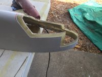
You've now got a wingtip with a big hole. You now need to form the 4 "walls" that provide mounting surface for the lights and finish out the space. I used heavy card stock, tape and trial and error till i got the walls laid out. I stole some of my kids play-dough and used it as a form to transfer some of the complex curves onto the cardstock where the walls meet the wingtip. I then covered the cardstock in clear packaging tape so the wall layup will not bond. I taped the 4 cardstock pieces carefully in place from the outside, these will now be the forms for the fiberglass.
I used some thickened epoxy to create filets all around the interior of the wingtip along the backside of the cardstock where it meets the wingtip. This is so the fiberglass does not make sharp 90 degree bend. I then put 5 layers of cloth with about a 1" overlap to get a good bond. Once the layup is dry, you should be able to easily remove the card stock.
I used 1/16" mirror plexiglass to cover the walls, so I simply lightly sanded the walls after I removed the cardstock. If you plan to paint, you might need to spend some more time and filler to get a nice smooth surface,
I thermoformed my lens using my shop vac as a source for vacuum, so first step was to build a vacuum box. I used some 3/4 MDF I had laying around and built a box 14"x22"x3". What that size? From what I could gather online, you want roughly 30% more material than your form to allow for stretching, etc. It was an educated guess. I cut a piece of pegboard to fit inside. I then glued and brad nailed some pieces of wood around the inside of the box so the pegboard would sit flush with the top. I also glued a couple piece of wood to support the pegboard in the center. Cut a whole in the middle of the box to fit your vacuum hose. Now line the top perimeter of the box with weather stripping to provide a good seal.

You need some sort of frame to hold the .09 Lexan. I used some 1x2 pieces cut to the same size as my box. I used my Kreg jig to make a quick square frame. I then cut 4 identical pieces and match drilled .25 holes towards the outside of the frame, 2 on each side to be used and secured with screws and wingnuts. It was a pretty crude frame and you might do better, the idea is to be able to hold the piece of Lexan securely and form and maintain an air tight seal against the vacuum box. Mine was essentially a clamp between 2 pieces of wood. I lined the portion of the frame where the lexan sits with some thin .0625 weather stripping.
The cutout from the wingtip will be the form for the lens. This need to be reinforced since you will be pulling a good vacuum down over top of it, you want it to maintain it's shape and it needs to be elevated slightly when it sits on your vacuum box. This is due to the Lexan being in a frame and not necessarily flush to the vacuum box. I used my card stock to mock up templates for some wooden supports I cut from scrap lumber which I epoxied into the cutout. It sits on the box open side down with what is the edge of the wingtip pointing straight up.

Once you have reinforced the form, you want to make sure the surface is perfect. Any imperfection will show in the lens. Use filler and sand if needed.
When you are ready to form, the first step is to "dry" the lexan. Load a piece of Lexan in your frame and put it in the oven at 180 for 5+ hours. You can get steam bubbles if you skip this drying step. My frame was a perfect width where it would rest on the same supports used for holding the oven racks. Otherwise you will need to support the frame somehow in the middle of the oven. You don't want anything below as the Lexan will sag when you raise it to forming temperature.
Make sure everything is in place before starting the forming step, because it happens fast. Vacuum box, vacuum on, helper, gloves to handle the hot frame, etc. I coated my form in petroleum jelly, I read somewhere it helps. When I was ready to form, I removed the frame and Lexan and bumped the oven temp up to 350. Once it reached 350, I put the frame back in. You have to keep a close eye on things because you are watching the sag of the Lexan as the indicator of temp. I found that once the middle of the lexan was about 2.5" below the frame it was ready. I had my vacuum box on the floor next to the oven. Open the door, pull out the frame and immediately push evenly down over your form. You have to eyeball things a bit, but your frame needs to come down and land on the weatherstripping around the perimeter of the forming box to make a good seal. Once the seal is made the lexan will draw down. Rather than pulling a hard vacuum, I found that I got a better part by pulling the vacuum hose out of the hole as soon as the Lexan forms around the part and holding it close to the hole, acting like a partial vacuum, otherwise the lexan would wrap around the under side of the part which makes it hard to get out. You have to be very quick as it happens very fast. It might be better to have a helper. Another approach would be to build a solid support for the part so the lexan cant pull under. Pop the form out as soon as it cools enough to handle but hasn't fully hardened. It's easier when it's still hot but solid.
Here is a video of the actual forming: https://youtu.be/9ZilVMfcSJg
If you get the lexan too hot, it tends to "print" easier,,,and it looks wavy and shows imperfections in the form easier. I found there is a very small sweet spot at 2.5" inches of sag. Too cold or too slow from oven to form and it will be too stiff to properly form. Also, I had better results with the Lexan I ordered from Amazon, which turned out to be Bayer Makralon. The brand from Home Depot and Lowes I did not have much luck with. I also tried Plexiglass but found that it was very brittle and would crack easy when I tried to trim it. Keep in mind it smells up the house pretty good too, not to mention using the food oven for heating plastic may not be the best idea. My kitchen closes off from the rest of the house and I opened a window with a fan blowing out.
I pulled the formed part out of the frame and rough cut the excess material. Then I carefully marked the rough trim line by placing the lens in place. I then carefully final trimmed with my pneumatic 1/2"x24" mini belt sander and a lot of trial fitting. I radiused the inside corners and sanded the edge with 220 grit when I was happy with the fit.

My lens shrunk slightly, so I ended up using some quick fair compound in the flange to get a perfect looking fit. Also, where I radiused the corners of my lens the cut in the wingtips are square, again I used some putty to make everything perfect.
Once you're happy with the fit, you can drill the lens to the flange. I drilled and clecoed #40 first, then went back and opened them up for #6 screws and riveted on plate nuts using soft flush rivets. I originally planned to use countersunk screws, but I didn't have good edge distance on a couple of holes and I read Lexan can crack if countersunk screws are used. I settled on some low head (.063) socket head screws (Mcmaster 90666A002).
You can now mount your lights and add any trim. I trimmed the interior area where the lights mount in .0625 mirrored plexiglass. I used adhesive caulk to hold it on,

LED Nav/Strobe lights are Whelen OR6501GE & OR6501RE. Spendy but I got a decent deal from http://teamaerodynamix.com. Landing lights are Baja Designs 48-7801, Compact and 2100 Lumens @ 21 watts each.
It was a long process but it was fun and I learned a lot. Hope you enjoyed.
Stuff You'll Need:
MDF to make 2 full size airfoil forms
Enough foam to make 2 wingtips the thickness you require
Fiberglass Cloth & Resin (Epoxy or Vinylester)
QuickFair or filler of your making
Lightweight spackle or Polyurethance+Microballoons
Sandpaper - I suggest 80 - 120 - 220
Nichrome wire - 22 gauge
Foil Tape, min 1.5 inch wide
Power source for hotwire - Battery Charger, etc.
High Build Primer
Make the Forms:
To start, I rough cut a piece of MDF and set it up against the outboard edge of my wing and traced the airfoil with a sharpie. I cut to the line using a band saw and jig saw. I then used a random orbital sander to finish until the line was just gone.
My plan was to mount the tips flush, not overlap....so I reduced the form by another .0625" to allow for the fiberglass layup thickness. I drew a line .0625 in from the edge by using a scrap piece of aluminum the correct thickness and dragging it around the form with a sharpie. I then sanded the form down to the new line. Because I need two identical forms to hotwire the foam, I traced the completed form onto another piece of MDF and rough cut. Using a few screws, I screwed the two pieces of MDF together and used a flush cut router bit to make an exact copy of the first form.
The two forms will sandwich the foam and the hotwire will glide along the forms resulting in a airfoil shaped block of foam. The two forms need to be exactly in line with each other during this process. I am sure there are many ways to ensure the forms are inline, but I simply match drilled the forms with a couple of 3/8 guide holes while the forms were screwed together which threaded rod will go through later in the process.
I made my wingtips 10" wide, primarily because a single 4'x8' sheet of 2" foam supplied enough material. But you can make them any width you want, just glue together enough foam.
Using a framing square, I laid out lines on my workbench to match the distance between the 3/8 guide holes in the forms. The width of my wingtips are 10", so the layout is 10" + 1.5" to account for the 2 MDF forms. I then made 4 supports from some scrap 1x2, 2 for the front and 2 for the rear. The pairs were match drilled and long enough to suspend the forms and foam in the air over my bench. I drilled the 4 supports with a Kreg jig I use for wood joinery, but it's perfect for attaching wood at right angles. You'll also want to ensure the ends mounting down to your work surface are square, I cut mine using a chop saw.
Prepare the Foam:
I used one of the airfoil forms to trace the airfoil 5 times on my 4'x8' sheet of 2" thick polystyrene foam I picked up at Home Depot. I also drilled the foam through the 3/8 guide holes while I was tracing the airfoil.
I rough cut the sheet into 5 pieces using the tracings in the previous step. I used an old hand saw I had laying around.
The foam I purchased had foil on 1 side and plastic on the other. I peeled this off so i could glue the 2" pieces together to get 10" total. I used 3M 78, which is a FOAM safe spray adhesive. If you use a different glue, test it on some scrap foam.....because many of the solvents in glue will eat polystyrene, especially the spray adhesives.
To glue everything together, I ran 2 threaded rods up through the guide holes on one of the forms so the rods were sticking up in the air. I slipped the first piece of foam down over the rods then sprayed the inside end with adhesive along with the subsequent joining end of the next piece. Rinse and repeat until you get to the last piece. You don't want adhesive on the outside ends between the forms and foam, we just want to glue the pieces of foam together to get our desired thickness. I slipped the second form onto the rods and snugged the whole assembly together while the adhesive dried. I went for tight but I didn't want to crush the foam.
Hotwire:
Once the adhesive is set, you are ready to hotwire. I set up the assembly using the 4 supports screwed down to my workbench, so the forms and foam are suspended over my bench.
I made a hotwire tool with a scrap piece of 1x2 and some scrap fuel strap (.025 4130 bent at 90 degrees) It needs to be wide enough for the width of wingtip you are building. You want the wire to glide along the two MDF forms. The Nichrome wire I purchased from Amazon. the wire needs to be as tight as possible.
For a power source I used a car charger. It seems the newer digital chargers are smarter than the old dumb transformer types, so I used an old 12V UPS battery to trick my charger into putting out the juice.
Once you have your hotwire tool ready, it's time to cut some foam. the idea is to have the wire glide along the top of your forms at a nice slow steady pace. Not too fast to drag the wire, but not too slow where you burn excessive foam. You can fix most imperfections when you fill the foam, but try to get a clean cut. Do one side, then flip the whole assembly in your supports and do the other side. Take it out of the fixture and you now have an airfoil shaped chunk of foam the thickness of your planned wingtip.
Now we will create the Hoerner shape. To do this, we will apply foil tape along the edge of the foam for the hotwire to ride on. On the lower inboard side of the wingtip, I made a line 1 inch from the edge. I carried this to about the center of the front of the airfoil. Now on the TOP of the OUTBOARD edge of the airfoil, I came down about .25" inch from the edge. There is nothing hard and fast about .25. but this will determine the thickness of the outboard edge of the wingtip. If you want thicker, make the dimension bigger.
To hotwire this, I plunged the hotwire into the foam until just making contact with the foil tape, then gently drug the wire trying my best to keep the wire square for a nice even pull. The video shows this in more detail.
Now you've got a funny looking airfoil-hoerner sculpture. The next step is to put the front radius on. From this point on it's more up to you and how you want the final shape to be. I followed the convention outlined in the video (https://youtu.be/RoOh-fgI8oU) which is to use the width of the wingtip as the radius of the front curve, 10" in my case. I am happy with the look and the way it came out. I used a piece of safety wire around a sharpie to draw the 10" radius from the front inboard edge of the airfoil to outside edge. I then used my hotwire tool held vertical to the foam
and rough cut the radius.
Prepare the Form:
You will end up with a blunt edge on the front of the airfoil where you cut the radius. Use a rough file or rasp to blend this blunt edge into the existing airfoil. I went ahead and ever so slightly radiused the outboard edge of the wingtip to the point where the airfoil is the thickest. Seems to be about 1/3 of the way back from the front. This was done by eyeball until I got a pleasing shape.
I then used some 80 grit sandpaper to rough sand any ripples from hotwire and generally level the foam. I used some 120 to put a nice radius on the outboard edge of the wingtip. You don't want any sharp edges since fiberglass will pull away if you try to layup over a sharper corner.
I then used some lightweight spackle to go over the form. sand. fill. sand. fill. You want a nice smooth surface to layup over. Any imperfection will transfer into the fiberglass. I read in the Bingelis book that Polyurethane mixed with Microballoons makes a good mix to cover foam forms. I had already used spackle before I found that tidbit, but you might want to explore that method. You'll want to make sure the entire form is covered, because paint and certain resins will eat foam.
After getting things as smooth as possible, I put a couple of coats of rattle can spray paint. I used orange because I wanted to be able to see the form as I was laying up, to make sure there were no air bubbles.
To prep for layup, I waxed the painted form with 4 coats of good carnuba car wax I had in the garage. I then sprayed 3 coats of PVA.
Layup the Fiberglass:
My layup schedule was 4 layers of 8.8 oz Bi-directional cloth from Spruce. (01-00642) There was no science in that choice, just a guess. They seem to be pretty sturdy and came out around 7 lbs. each.
I used System 3 Silver Tip Epoxy as my laminating resin. It is a popular choice among home boat-builders. No amine blush and simple 2:1 mix ratio. It can also be post-cured at higher temps to improve the structural properties, which is a bonus for room-temp cured epoxies. Make sure your foam is 100% protected if you use Polyester or some other non-foam safe resin.....or all that hard work will melt away.
Attach the Wingtips:
I will not go into detail on attachment, but I ended up using piano hinges. I didn't want to have to undo a bunch of screws every year at annual. I followed the steps the RV guys have outlined. The only exception is I built an access panel on the top of the wingtip to access the hinge pins, since the Bearhawk's tip rib extends all the way back, unlike the RV method of securing the hinge pins.
I followed this method: [FONT=Verdana, Arial, Helvetica, sans-serif]http://websites.expercraft.com/n51pw...y&log_id=23961[/FONT]
I used .040 strip of 2024 as my spacer, since there is no cutting of these wingtips. Also, since there is no gelcoat on my homebuilt wingtips, they were translucent enough for me to mark the hinge and drill based on marking on the hinge.
Fair the Wingtip:
Once I had the wingtip mounted, I used Quick Fair (a commercial fairing compound) to level and get a nice surface on the wingtips. This requires several thin coats and lots of sanding. I use a 3M semi-flexible longboard. 80 grit for rough, then 120, then 220. Depending on the quality of finish you want will determine how much time is spent here.
Prime:
I applied high build epoxy primer next, sanding between coats.....until i get a perfect surface. Once you are happy, they are ready to be painted or further modified for lights, etc.
LENS:
First, I needed the shape of the lens. To know how big I wanted, I made some cutouts of poster board to represent the size of my landing light and nav/strobe. I used these to determine how far back to go so I would end up with enough mounting area for the lights. Once I had this I drew the cut lines on the wingtip. Keep in mind your position lights (red & green) are supposed to be visible 110 degrees.
Once I had the wingtip marked up with a fine sharpie, I used a Dremel cutoff wheel to carefully cut the lines, but I left small uncut areas in the corners so the piece we want to remove stays securely in place for the next step, which is making the lens mounting flanges.
I marked parallel lines to the cut lines on the inside of the wingtip, 3/4" inside and 1.25" outside. The idea is to have 1/2" flanges after trimming and the 1.25 overlap outside gives good bonding area to the inside of the wingtip. I cleaned the area inside the cut lines with air then wiped with solvent to clean any dust from cutting. Next I used clear packing tape to cover the entire area inside the cut lines, this will prevent the fiberglass from bonding.
I now cut some fiberglass cloth so it would span the lines marked previously. It should protrude about 3/4 inch into the area where the lens will be and 1.25 outside the line where it will bond to the wingtip. I ended up using 4 pieces to go all the way around, I found it eaiser to work with multiple pieces. Once I had the glass cloth shapes cut, I made 6 more of each shape for a total of 7 layers. I scuffed up the area outside the cut line where there is no tape (careful not to move or mess up the tape) then cleaned with some alcohol. For the flanges, I wet out the cloth on a piece of parchment paper then put it in place, lining it up with the lines previously marked.
Once your flanges have cured, you can carefully cut the rest of the lens area out. Be careful not to cut beyond the thickness of the wingtip, you don't want to get into you new flanges. Once you've removed the material you should be able to work the piece free since the cloth will not bond to the packing tape underneath. Be careful not to damage the cutout, as it will be the form for your lens. Now you can trim the flanges back to .5"
You've now got a wingtip with a big hole. You now need to form the 4 "walls" that provide mounting surface for the lights and finish out the space. I used heavy card stock, tape and trial and error till i got the walls laid out. I stole some of my kids play-dough and used it as a form to transfer some of the complex curves onto the cardstock where the walls meet the wingtip. I then covered the cardstock in clear packaging tape so the wall layup will not bond. I taped the 4 cardstock pieces carefully in place from the outside, these will now be the forms for the fiberglass.
I used some thickened epoxy to create filets all around the interior of the wingtip along the backside of the cardstock where it meets the wingtip. This is so the fiberglass does not make sharp 90 degree bend. I then put 5 layers of cloth with about a 1" overlap to get a good bond. Once the layup is dry, you should be able to easily remove the card stock.
I used 1/16" mirror plexiglass to cover the walls, so I simply lightly sanded the walls after I removed the cardstock. If you plan to paint, you might need to spend some more time and filler to get a nice smooth surface,
I thermoformed my lens using my shop vac as a source for vacuum, so first step was to build a vacuum box. I used some 3/4 MDF I had laying around and built a box 14"x22"x3". What that size? From what I could gather online, you want roughly 30% more material than your form to allow for stretching, etc. It was an educated guess. I cut a piece of pegboard to fit inside. I then glued and brad nailed some pieces of wood around the inside of the box so the pegboard would sit flush with the top. I also glued a couple piece of wood to support the pegboard in the center. Cut a whole in the middle of the box to fit your vacuum hose. Now line the top perimeter of the box with weather stripping to provide a good seal.
You need some sort of frame to hold the .09 Lexan. I used some 1x2 pieces cut to the same size as my box. I used my Kreg jig to make a quick square frame. I then cut 4 identical pieces and match drilled .25 holes towards the outside of the frame, 2 on each side to be used and secured with screws and wingnuts. It was a pretty crude frame and you might do better, the idea is to be able to hold the piece of Lexan securely and form and maintain an air tight seal against the vacuum box. Mine was essentially a clamp between 2 pieces of wood. I lined the portion of the frame where the lexan sits with some thin .0625 weather stripping.
The cutout from the wingtip will be the form for the lens. This need to be reinforced since you will be pulling a good vacuum down over top of it, you want it to maintain it's shape and it needs to be elevated slightly when it sits on your vacuum box. This is due to the Lexan being in a frame and not necessarily flush to the vacuum box. I used my card stock to mock up templates for some wooden supports I cut from scrap lumber which I epoxied into the cutout. It sits on the box open side down with what is the edge of the wingtip pointing straight up.
Once you have reinforced the form, you want to make sure the surface is perfect. Any imperfection will show in the lens. Use filler and sand if needed.
When you are ready to form, the first step is to "dry" the lexan. Load a piece of Lexan in your frame and put it in the oven at 180 for 5+ hours. You can get steam bubbles if you skip this drying step. My frame was a perfect width where it would rest on the same supports used for holding the oven racks. Otherwise you will need to support the frame somehow in the middle of the oven. You don't want anything below as the Lexan will sag when you raise it to forming temperature.
Make sure everything is in place before starting the forming step, because it happens fast. Vacuum box, vacuum on, helper, gloves to handle the hot frame, etc. I coated my form in petroleum jelly, I read somewhere it helps. When I was ready to form, I removed the frame and Lexan and bumped the oven temp up to 350. Once it reached 350, I put the frame back in. You have to keep a close eye on things because you are watching the sag of the Lexan as the indicator of temp. I found that once the middle of the lexan was about 2.5" below the frame it was ready. I had my vacuum box on the floor next to the oven. Open the door, pull out the frame and immediately push evenly down over your form. You have to eyeball things a bit, but your frame needs to come down and land on the weatherstripping around the perimeter of the forming box to make a good seal. Once the seal is made the lexan will draw down. Rather than pulling a hard vacuum, I found that I got a better part by pulling the vacuum hose out of the hole as soon as the Lexan forms around the part and holding it close to the hole, acting like a partial vacuum, otherwise the lexan would wrap around the under side of the part which makes it hard to get out. You have to be very quick as it happens very fast. It might be better to have a helper. Another approach would be to build a solid support for the part so the lexan cant pull under. Pop the form out as soon as it cools enough to handle but hasn't fully hardened. It's easier when it's still hot but solid.
Here is a video of the actual forming: https://youtu.be/9ZilVMfcSJg
If you get the lexan too hot, it tends to "print" easier,,,and it looks wavy and shows imperfections in the form easier. I found there is a very small sweet spot at 2.5" inches of sag. Too cold or too slow from oven to form and it will be too stiff to properly form. Also, I had better results with the Lexan I ordered from Amazon, which turned out to be Bayer Makralon. The brand from Home Depot and Lowes I did not have much luck with. I also tried Plexiglass but found that it was very brittle and would crack easy when I tried to trim it. Keep in mind it smells up the house pretty good too, not to mention using the food oven for heating plastic may not be the best idea. My kitchen closes off from the rest of the house and I opened a window with a fan blowing out.
I pulled the formed part out of the frame and rough cut the excess material. Then I carefully marked the rough trim line by placing the lens in place. I then carefully final trimmed with my pneumatic 1/2"x24" mini belt sander and a lot of trial fitting. I radiused the inside corners and sanded the edge with 220 grit when I was happy with the fit.
My lens shrunk slightly, so I ended up using some quick fair compound in the flange to get a perfect looking fit. Also, where I radiused the corners of my lens the cut in the wingtips are square, again I used some putty to make everything perfect.
Once you're happy with the fit, you can drill the lens to the flange. I drilled and clecoed #40 first, then went back and opened them up for #6 screws and riveted on plate nuts using soft flush rivets. I originally planned to use countersunk screws, but I didn't have good edge distance on a couple of holes and I read Lexan can crack if countersunk screws are used. I settled on some low head (.063) socket head screws (Mcmaster 90666A002).
You can now mount your lights and add any trim. I trimmed the interior area where the lights mount in .0625 mirrored plexiglass. I used adhesive caulk to hold it on,
LED Nav/Strobe lights are Whelen OR6501GE & OR6501RE. Spendy but I got a decent deal from http://teamaerodynamix.com. Landing lights are Baja Designs 48-7801, Compact and 2100 Lumens @ 21 watts each.
It was a long process but it was fun and I learned a lot. Hope you enjoyed.
Attachments
Last edited: