Bearhawk Aircraft Bearhawk Tailwheels LLC Eric Newton's Builder Manuals Bearhawk Plans Bearhawk Store

Announcement

Collapse
No announcement yet.

Long wing Bearhawk

Collapse
X
 
  • Filter
  • Time
  • Show
Clear All
new posts

  • Long wing Bearhawk

    I am thinking about the merits of extending the wings on the Bearhawk 4-place. I am keen to hear the thoughts of the group.

    It seems like a very easy modification, which could have big advantages - think WingX extensions for a Cessna.

    Even just an extra foot span in total, or better yet a foot more on each wing-tip, could make a measurable difference. On a Maule, which is a similar size and horsepower to the Bearhawk 4-place, less than a foot longer wingspan on the "long wing" Maule makes for faster cruise speeds, slower stall speeds - better performance at both ends, compared to the "Universal Wing" and "Short Wing" Maule variants.

    The extension could be completed in two ways.
    Either a longer fibreglass wing tip, which would require moulds to be made - but would then enable production of extended wing tips to bolt on to any aircraft.
    Or adding an extra aluminium bay of narrow-width. It would perhaps be a few days work at most, but any parts made in the process could not easily be reused for other aircraft.

    I can only think of one real downside - the g-load limit would be reduced a little I assume. However the highest g-load I have ever seen is less than 50% of the safe limit, so perhaps only 35% of the ultimate limit.

    Anyone have an input on that idea?

  • #2
    How does the longer wing achieve performance increases on both ends? I understand the increased lift, but I would assume that would come with an increased drag penalty. I'm no engineer, so you may need to draw it in crayon for me.

    Comment


    • #3
      This has been discussed before either here or in the old yahoo group...I can't remember. I also can't remember the issues.

      I would like to build some Hoerner tips that add 1' of span to each wing. I've been contemplating how to accomplish this but decided to not think about it much till I finish the fuselage and bring the wings into the garage.
      Scratch Built 4-place Bearhawk. Continental IO-360, 88" C203 McCauley prop.

      Comment


      • LukeS
        LukeS commented
        Editing a comment
        I had thought about Hoerner wingtips too, but the project I bought came with regular ones, so the Hoerner tips may wait. Cost and time are both big factors right now. There's little doubt in my mind that you should have your bird in the air before I finish mine, so if you go that route I can't wait to read how you like them.

    • #4
      Originally posted by LukeS View Post
      How does the longer wing achieve performance increases on both ends? I understand the increased lift, but I would assume that would come with an increased drag penalty. I'm no engineer, so you may need to draw it in crayon for me.
      That was my initial assumption in the first place too.

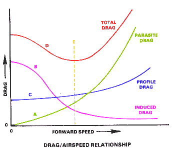
      Right up until some people, who clearly remembered their classes in aerodynamics better than me, reminded me about some basic principles like aspect ratio and the effects of it. Like the fact a high aspect ratio wing produces less induced drag. I think that's because the angle of attack of the wing in cruise is more favourable. At relatively low airspeeds, there isn't much parasitic drag to speak of, so overall a longer wing reduces the drag of the aircraft.

      They also pointed to the Maule and WingX Cessna's as examples. At which point I also remembered about aircraft like the Lancair Legacy which do the same. Hard to argue with real world numbers.
      Last edited by Battson; 02-16-2016, 09:46 PM.

      Comment


      • Phil
        Phil commented
        Editing a comment
        Maules use the same antique USA35B airfoil as Cubs do. This airfoil has a pretty severe torsional moment. At Cub cruise speeds it's not a big deal, but at Maul speeds I'm betting the tail is working pretty hard, creating a lot of induced drag to keep the nose up. Increasing the wing area would decrease the lift coefficient needed in cruise, and decrease the pitching moment, there by reducing the load and drag on the tail.

        The NACA 4412 on the Bearhawk doesn't have that much torsional moment in the first place, so the extended wings will probably cost you a couple knots of cruise speed. The comparison with aspect ratio only applies if the total wing area is the same. So you'd have to lengthen the wing, and shorten the cord to see a speed increase from the reduced aspect ratio. I could look up the applicable calculations if you're that curious.

    • #5
      Originally posted by whee View Post
      I would like to build some Hoerner tips that add 1' of span to each wing. I've been contemplating how to accomplish this but decided to not think about it much till I finish the fuselage and bring the wings into the garage.
      That is precisely one of the two options I have been contemplating.

      For my STOL and cross-country type flying, I can't see any disadvantages of a longer wing.

      I know one of the main reasons pilots prefer a shorter (low aspect ratio) wing is aerobatics, because they are stronger and more manoeuvrable.

      Comment


      • #6
        Originally posted by Battson View Post
        That was my initial assumption in the first place too.

        Right up until some people, who clearly remembered their classes in aerodynamics better than me, reminded me about some basic principles like aspect ratio and the effects of it. Like the fact a high aspect ratio wing produces less induced drag. I think that's because the angle of attack of the wing in cruise is more favourable. At relatively low airspeeds, there isn't much parasitic drag to speak of, so overall a longer wing reduces the drag of the aircraft.

        They also pointed to the Maule and WingX Cessna's as examples. At which point I also remembered about aircraft like the Lancair Legacy which do the same. Hard to argue with real world numbers.
        I suppose the key question would be whether the reduction in induced drag from the higher aspect ratio would outweigh the increase in parasite drag of the extra structure in the breeze. Has anyone asked Bob how he arrived at the wingspan? I'm doubtful that it's related to his hangar size, and I know that aerobatics was not one of his concerns when he drew it, being that he'd already been through his aerobatic phase.

        Comment


        • #7
          The Bearhawk already has adverse yaw. That may play into this. Also, people that I know that have flown the C185 with the extended tips thik it's a waste of time and don't like them. YMMV.

          Comment


          • Battson
            Battson commented
            Editing a comment
            There are dozens more guys on the BCP forum who would disagree about the extended tips being a waste of time, I don't think I've heard that sentiment before from anyone flying on floats or off-airport.

        • #8
          Originally posted by alaskabearhawk View Post
          The Bearhawk already has adverse yaw. That may play into this. Also, people that I know that have flown the C185 with the extended tips thik it's a waste of time and don't like them. YMMV.
          I only personally know 1 guy with WingX on his C180 and he loves it. In the past there has been a ton of discussion about WingX on BCP and I can't remember a single person that wish they hadn't done it...but you know how internet forums are. The adverse yaw increase with the long wing Maule is noticeable and I image extending the wings on the BH would also increase the adverse yaw. The BH has plenty of rudder to counter it so to me that really isn't an issue.
          Scratch Built 4-place Bearhawk. Continental IO-360, 88" C203 McCauley prop.

          Comment


          • #9
            When I first thought about tips a few months ago I was thinking I could build a set of crude Hoerner-ish tips out of aluminum pretty easily. Basically wrap sheet aluminum along the top of the wing overhanging however far I wanted. The bottom sheet would simply run at an angle from the bottom of the wing out to the overhanging sheet. Crude and too simplistic but should work as proof of concept.
            Scratch Built 4-place Bearhawk. Continental IO-360, 88" C203 McCauley prop.

            Comment


            • #10
              I've got one of my hoerner tips laid up and fitted. I am using hinges to attach them, similar to how many of the RV guys are doing it. While they are far from complete, it hasn't been too bad for this first-time composite builder. I only made mine 10" wide, but making them 12" would be a simple mod. I started with a 4x8 sheet of 2" foam from home Depot. IMG_0944.JPG
              Attached Files

              Comment


              • Battson
                Battson commented
                Editing a comment
                Did you fibreglass straight over the foam plugs?
                Or did you use those plugs to produce female moulds, which you then fibreglassed inside?

                Having answered that, are you happy with the way they turned out?

              • mswain
                mswain commented
                Editing a comment
                I just glassed the foam plug. After some time with fairing compound and a sander, I am very happy with the result. I will be making the cutouts for the lights and forming lenses as a next step. I plan to have LED landing lights and Whelen Strobe/Position lights houses under a formed plexiglass lens.

              • Battson
                Battson commented
                Editing a comment
                Thanks very much for the reply, I hoped you would say that! Did you gel coat the fibreglass, or did you use an alternative compound? I am looking for a spray on coating which I can sand off afterwards.

                What sort of foam did you choose?

            • #11
              MSWAIN,
              Wondering how TIG works on fiberglass?
              Sorry. Saw the picture and couldn't resist. Looks good, thinking of doing the same thing.

              Doug

              Scratch building Patrol #254

              Comment


              • mswain
                mswain commented
                Editing a comment
                Terrible, I thought tig was supposed to work on all material. That's what the salesman told me.

            • #12
              This discussion has inspired me to accelerate my side project: An optimized set of wingtips for the (4 place) Bearhawk. I won't need them for a couple years, but right now I have access to the entire library of the Air Force Research Lab and the Air Force Institute of Technology which has enough references to keep me busy for a lifetime, including Dr. Hoerher's texts on aerodynamics and his original study on wingtips. So I'm going to start working on this now.

              I am a big fan of extracting as much "free" performance out of this airplane as possible, i.e., performance gains without additional weight and complexity. Even if it's only on the order of 1-2%, it all adds up at the end. So my plan is to design, model, redesign, build, and ultimately flight test a new pair of tips, and hopefully generate enough data to quantify their overall contribution to the Bearhawk's performance, whether good or bad. I'll report back here when I'm done, but don't hold your breath cause it's gonna take time.

              Also, I haven't seen the drag profile of the Bearhawk but typically parasite drag is the predominant force in cruise flight and it increases with wing area. There may be other factors at play in the Maule, WingX's, etc, but normally elongating a wing will cause slower speeds on both ends of the envelope.

              Nic
              BH 1217

              Comment


              • #13
                Originally posted by nichzimmerman View Post
                Also, I haven't seen the drag profile of the Bearhawk but typically parasite drag is the predominant force in cruise flight and it increases with wing area. There may be other factors at play in the Maule, WingX's, etc, but normally elongating a wing will cause slower speeds on both ends of the envelope.

                Nic
                BH 1217
                I think that's true for modern fast aircraft. At the 1930's speeds we fly, just like with a glider, I understand the parasitic drag is much less of a concern. I believe that is why longer wings make aircraft faster in our type of plane.

                This image ROUGHLY illustrates the typical shape of each drag curve.
                Last edited by Battson; 02-18-2016, 05:27 PM.

                Comment


                • #14
                  Thinking aloud, and seeking feedback:

                  Would it be sensible to fabricate some wing extensions which screw onto the wing like the current wing tips do (but I am not thinking bigger tips - I mean extensions - see picture below), and do some flight testing with a longer wing?

                  I mean extensions like this:


                  Now - I realise that in the Cessna, they put in a small additional capstrip length at the wing tip to make the wing stronger, but after some research it appears they DON'T add any capstrip into the wing extension, or connect the spar web to the extension. The extension appears to only attach to the outer skin of the wing, with a short overlap. However, note the Bearhawk has no capstrip in the last bay(s) of the wing, which could be more tricky to add more.

                  I have seen a range of planes where the tips of the wings are attached only with screws - usually not that many screws either... Mostly they are still aerofoils but they taper off in the modern composite style, so looking from the outside I don't think this is a "stupid" idea. You would also be increasing the stresses with an extended tip, perhaps 40% as much as a bigger extension like this would?

                  Just jump in here if you think that's a fundamentally stupid idea! Otherwise, a few supplementary thoughts:

                  Ok - so what are the problems with this idea?

                  One concern would be whether any number of screws around the outer skin (through the end-rib's flange) would be sufficient to support the additional stresses applied to the wing by the extensions, and if so, how many screws do you need? Although would that really be a concern? Other aircraft use this design already, and even with only ~20 screws the wing tips are pretty well anchored in place. Of course you would want countersunk screw heads, not truss heads, or it would be ugly and draggy.

                  Then one would need to consider whether the additional stresses of drag and lift, transferred to the wing by the extension, could be supported in the long term by the semi-monocoque design of the existing wing (without cracking the existing skin through cyclic stress. I imagine the additional lifting forces and drag would be considerable. I wonder if they would overstress the outer part of the wing skin and rib flange, if enough screws were used to transfer the force evenly. Thoughts?

                  Afterthoughts:

                  You would want to include an inbuilt tip, so as to avoid the additional weight and complexity of attaching the existing wing tips to the extensions. The existing wing tips appear to focus on drag minimisation only, to my eye they really appear to do very little in terms of lift creation.

                  If the temporarily extended wings don't produce better performance, no foul - just replace the original wing tips and get on with life.
                  If the temporarily extended wings do perform better - great - if necessary, the screws could be replaced with rivets and the spars webs could be spliced together. Or, one could even leave the screwed-on extensions in place as they are, as a long term solution. That would be dependant on the extensions being very ridged, and the stresses being well distributed.
                  If you went to the trouble of extending the cap strips onto a stub spar, and adding permanent extensions to the wing - then you would doubtlessly be pretty annoyed if there were no good performance outcomes. It would NOT be hard to add stiffeners to extend and connect the capstrips into the new stub spar in the extension, but it would be very permanent.
                  Last edited by Battson; 02-18-2016, 11:25 PM.

                  Comment


                  • #15
                    Rough calculation using Hiscocks and Shrenk's approximation, on the normal wing, you're seeing about 323 lbs. at that first bay at 4.4g (4752 lbs). If you added two bays (28 inches), the resultant force at that original end bay goes up to a little over 700 lbs. at 4.4g. And the forces are additive each 19.5 inches inward by about 10% each time (+437, +470, +490, etc.). So I guess the thing to do is check each station and make sure it'll handle the load (I'm still learning the math behind that part). But my gut tells me you could pick a side of the spar, run a single cap strip top and bottom, and through your extensions and be good. Probably bolted through with a doubler. But that's my gut, not an engineer's opinion. But thinking again, that's going to be a bear without disassembling the wing on the end, what with the dividers, rib attach angles...

                    That's also the forward spar. Aft spar has capstrips that run all the way to the end. So that's a different kind if connection I haven't visualized.

                    So we're back to your original question: is there enough beef in the end rib to hold it all...
                    Last edited by Chris In Milwaukee; 02-19-2016, 10:00 AM.
                    Christopher Owens
                    Bearhawk 4-Place Scratch Built, Plans 991
                    Bearhawk Patrol Scratch Built, Plans P313
                    Germantown, Wisconsin, USA

                    Comment

                    Working...
                    X