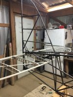
DavzLSA progress

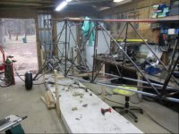
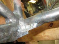
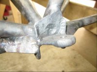
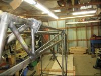
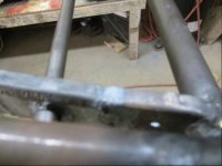
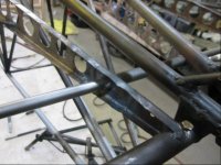
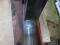
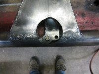
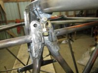
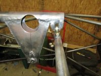
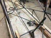
I got acetylene and O2 refill so im in the process of welding the gear legs brackets to the fuse. Its a lot of welding. Hope to be done soon. Ill have pictures soon.
 
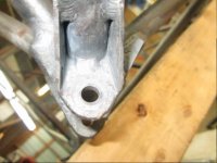
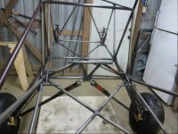
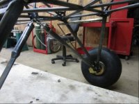
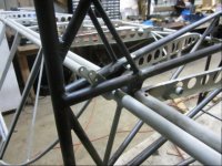
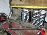
Hey guys, I got my gear leg attach point welded to my fuse now, Im going to put temporary braces from the gear leg to the bottom of the fuse and put my wheels together and get them mounted on the axles. I think once I get the wheels mounted to the axles I will set the brakes up and get them plumbed.
 
Sometime in the build process before painting the gear legs, do a careful alignment check for toe in/out. I thought I had jigged my gear to assure 0 deg toe in when welding the axles, they ended up with 2 deg toe in which I had to adjust out.
 
Hi Rod, how did you adjust the toe in and out after the gear leg attach brackets were finish welded to the fuse? My gear legs are store bought so I guess I could heat the gear legs by the axles and try to adjust them there?
 
Hi Rod, how did you adjust the toe in and out after the gear leg attach brackets were finish welded to the fuse? My gear legs are store bought so I guess I could heat the gear legs by the axles and try to adjust them there?

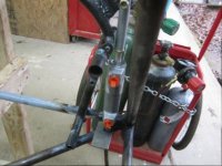
Mark sent me Bob's procedure. Like you said it involves heating the cluster at the axle to 900 to 1000 deg, using about an 8' pipe that slips over the axle and some careful geometry to move the end of the pipe the correct amount. Best done later in the project when you have weight on the gear. My wings and engine were installed at the time. In fact toe-in is best measured with weight on the gear and the gear spread 72" center to center on the tires. Bob wants 0 to 1/2 deg toe in.
 
Last edited:
HI Guys, Got some progress to report. Got the rudder pedals welded to the longerons, both front and back. having weirdness with getting the brake cylinder attach points welded in the correct spot so as not to interfere with the engine mount bolts. Any comments are welcomed. Here are the pictures.
 

Attachments

  • photo4654.jpg
    photo4654.jpg
    86.4 KB · Views: 0
  • photo4655.jpg
    photo4655.jpg
    71.5 KB · Views: 0
  • photo4656.jpg
    photo4656.jpg
    56.2 KB · Views: 0
  • photo4657.jpg
    photo4657.jpg
    83 KB · Views: 0
  • photo4658.jpg
    photo4658.jpg
    82.3 KB · Views: 0
  • photo4659.jpg
    photo4659.jpg
    57.7 KB · Views: 0
  • photo4660.jpg
    photo4660.jpg
    61.4 KB · Views: 0
  • photo4661.jpg
    photo4661.jpg
    77.8 KB · Views: 0
  • photo4662.jpg
    photo4662.jpg
    68.1 KB · Views: 0
  • photo4663.jpg
    photo4663.jpg
    81.1 KB · Views: 0
Dave

I e-mailed you some photos. I think your engine mount bushings are a bit further in than typical.

On mine(and I don't recall exactly why) my brake master attach tabs are on the inside of the fuselage(instead of the outside as shown in the plans). I also have a small tube welded in the "V" area that the lower master cylinder pivot is mounted to.
 
Brad can you tell me the distance from the fire wall frame to the rudder pedal mounts on your plane? Im using the measurements on the plans but from your pictures it looks as though your rudder pedals are further behind the fire wall frame than the measurements would indicate.
 
Dave

I didn't get a chance to stop at the airport and take a measurement. AFAIK, I positioned everything per the plans which do show the small cross tube welded in for the lower cylinder mount.

Did you apply the 1:2 scale called out on the plans?
 
Hi Brad, Yes I scaled the measurement per the the drawing but it came out in the same spot every time. Anyway here is what I ended up doing and I think it will be OK. I have full travel of the rudder pedals and it came out to be a pretty neat looking job, pics are enclosed.

David
 

Attachments

  • photo4664.jpg
    photo4664.jpg
    63.3 KB · Views: 0
  • photo4665.jpg
    photo4665.jpg
    51.6 KB · Views: 0
  • photo4666.jpg
    photo4666.jpg
    58.9 KB · Views: 0
  • photo4667.jpg
    photo4667.jpg
    58.2 KB · Views: 0
  • photo4668.jpg
    photo4668.jpg
    68.9 KB · Views: 0
Hi Dave, Great progress! Attached are some of my pictures of the brake/pedal area. I opted to move aft on my mounting locations to make room for cylinders with internal reservoirs. I am convinced that each install will be some what custom to get the geometry working correctly. My numbers aft of the firewall tubing are 2 1/4" and 4 1/4". I moved the adjustments all the way in and out on the cylinder mount to get a feel for the +/- of the movement. Then I cycled the peddles to make sure I could do so without the brakes coming on with heals on the floor.
 

Attachments

  • photo4669.jpg
    photo4669.jpg
    1 MB · Views: 0
  • photo4670.jpg
    photo4670.jpg
    1.2 MB · Views: 0
  • photo4671.jpg
    photo4671.jpg
    1.1 MB · Views: 0
Last edited:
HI Stephen, thanks for the info it looks like the bottom of your cylinders came out very close to the diagonal tube like mine did. I also noticed the angle of your rudder pedals, have you tryed them with the rudder attached yet? How much fore and aft movement did you have to move the rudder pedal to get full deflection of the rudder? Im thinking my pedals will be tilted aft a little to give the the deflection I will need. I wont know until I get the rudder attached to the rudder pedals. I know it will not require much movement. You do good work too, Ive been watching your progress also you are a great craftsman.
 
more progress today guys, I decided to work on the horizontal stab and get some of the trim tab control system installed. To avoid the getting the trim tab control horn on center line with the elevator push pull tube. I am installing a system like Btaz put on his plane. Today I got all the bushing welded into the horizontal stab ribs, I used some .050 plate to reinforce the area around the bushings on the rib webs. I welded the control horn to a tube that connected the 2 torque tubes in the stabilizers. An AN3 bolt will be used to retain the torque tubes in the tube between the 2 stabs that has the control horn. Here are the pictures
 

Attachments

  • photo4674.jpg
    photo4674.jpg
    61.5 KB · Views: 0
  • photo4675.jpg
    photo4675.jpg
    63.3 KB · Views: 0
  • photo4676.jpg
    photo4676.jpg
    51.5 KB · Views: 0
  • photo4677.jpg
    photo4677.jpg
    70.1 KB · Views: 0
  • photo4678.jpg
    photo4678.jpg
    73 KB · Views: 0
  • photo4679.jpg
    photo4679.jpg
    57.5 KB · Views: 0
Last edited:
Oh yes, having a rudder hooked up helps make the airplane noises coming from the shop sound even more real. Off of memory, it was about 1.5" of travel from neutral to full deflection. The way the angle worked, it was almost plum when fully applied. The clue that I used to set the final angle came from the rear pedal drawing on page 27. My front cables were made up keeping the front and rear pedals tracking parallel to each other. My biggest concern with the mounting location was the potential for a mechanical lock up by cam over.

I found Battson's video very helpful during this phase. https://www.youtube.com/watch?v=n_uk9o2N2zQ
 
HI Stephen, I see what you mean about that cam over lock, that would make your b hole suck seat cover? You would be stuck flying around in circles? And some good jams on the video too? My rudder pedal wont go over that far. I guess my geometry is a little different than that? The angles look about the same as mine and that amount of travel is about what I expected. Ill know more when I get the cables hooked up. Thanks for the info.
 
when I get my seat built and installed im going to have to try out the airplane noise thing it sounds like fun.
 
HI Stephen, I see what you mean about that cam over lock, that would make your b hole suck seat cover? You would be stuck flying around in circles? And some good jams on the video too? My rudder pedal wont go over that far. I guess my geometry is a little different than that? The angles look about the same as mine and that amount of travel is about what I expected. Ill know more when I get the cables hooked up. Thanks for the info.

I thought this was a non-issue once the system is primed with fluid?
 
True, but the over-cam can only happen if there is no pressure in the system. Which I would argue is a bigger problem.
 
Archer39J wrote: "True, but the over-cam can only happen if there is no pressure in the system. Which I would argue is a bigger problem."

Call me odd, but if my brakes failed, I'd rather not have rudder control problems as well because of it.
 
This all makes me think that once I get my brake system up I will manipulate it to see if I can get it in a failure mode. It would be a good thing to know at this stage of construction, a great time to fix any problems. That's what I like about the dialog we have here it always makes me think. Thanks guys.
 
Archer39J wrote: "True, but the over-cam can only happen if there is no pressure in the system. Which I would argue is a bigger problem."

Call me odd, but if my brakes failed, I'd rather not have rudder control problems as well because of it.

Think of a scenario where this becomes an issue. Is it in the air? How often are you at full rudder deflection while flying? And in that instant your brakes have also bled dry. That's when you can over-cam, which sure, would be catastrophic, but exceedingly unlikely...

Oh, and one would also have to have the habit of pressing the brakes while deflecting the rudder pedals. Is that common? Seems like not a great thing to do while, say, landing...
 
Last edited:
Various scenarios: prelanding brake checks, brake line failure at takeoff on longer flight with loss of fluid, while landing realize no brake but still using rudder for directional control (possibly continuing landing or a go around), etcetera. Common? No. But when fabricating pedals, why not make it so cam over can't happen? Seems wiser than wishful thinking that "a brake failure could never happen and if it did, oh if only I still had my normal rudder control available...oh darn it anyway."

Not really interested in arguing it. When designing and fabricating, do it trying to think of failure modes and ways to eliminate them or reduce their consequences.
 
Various scenarios: prelanding brake checks, brake line failure at takeoff on longer flight with loss of fluid, while landing realize no brake but still using rudder for directional control (possibly continuing landing or a go around), etcetera. Common? No. But when fabricating pedals, why not make it so cam over can't happen? Seems wiser than wishful thinking that "a brake failure could never happen and if it did, oh if only I still had my normal rudder control available...oh darn it anyway."

Not really interested in arguing it. When designing and fabricating, do it trying to think of failure modes and ways to eliminate them or reduce their consequences.

https://bearhawkforums.com/forum/bearhawk-4-place-plans-build/1100-rudder-pedal-placement

Oh, I see you actually commented on the thread where folks determined that:

A: The pedals will still over-cam even when located properly.

and

B: It's a non-issue.

Sorry, had to check where I had read all that before.
 
In all the demonstration I have observed, the complete systems are not serviced or connected. #1. the brakes are Not serviced . #2 the rudder cables are Not connected. #3 the Rudder stops controlling the travel are Not employed. #4 the break manual has Not been taken in consideration concerning the geometry providing the break pressure required. If you are using Matco brakes check the book. #5 where are the return springs? One must look at the overall system not a part of it. Yes, I could make my peddle pop over center if the system was not complete. Stinger;)
 

Attachments

  • photo4682.jpg
    photo4682.jpg
    1.5 MB · Views: 0
Thanks for the info Stinger, it is my intention to check everything once the whole system is installed and serviced. I think the video is what opened the can of worms here. But as I have said the dialog here is good for me and makes me think about things I would not otherwise consider. Thanks for your and everyone else input.
 
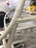
HI Guys, I think there will be a davzLSA 2.0 in the near future. Im not giving up on my LSA but I have had to do some major soul searching about my welding. This is my first attempt at such a massive welding project and to be honest Im not very good at it. Im a telephone man for a living not a welder. To me the safety of my family and myself is more important than my pride in my ability to make aviation grade welds on my airplane. I have a friend who is an expert aviation welder and I trust his opinion. At this point I am weighing my options. I might be able to salvage the fuselage I have but the jury is still out on that. I can buy a fuselage or I may just buy another tubing kit and try it again. One thing is for sure I now have plenty of practice and I believe I could do a better job the second time around. I have not made a decision yet, I want to haul the fuselage down to Florida and get my friend to evaluate it and see if it can be salvaged. Ill keep you guys up to date on what Im going to do if anyone is interested. Thanks for all the support all you guy have offered.
 
Keep us posted. I enjoy watching your progress. As builders we can all relate to making decisions every day that we can live with. Looking forward to version 2.0 or even 1.1 :)
 
Thanks for the encouragement Stephen, Im leaving in the morning for Jacksonville where my friend lived. I have the fuse strapped to my Ranger pickup truck, it really looks stupid I just hope it stays on the truck. I guess I can think of it as its first test flight????
 
Ask and ye shall receive sir, it was a fun trip, the wind was blowing like crazy so I really had a huge sail on the top of my truck so I was not able to drive over about 60 miles an hour, it took about 10 hours to get down there. See I told you it looked stupid???? The fuse is being evaluated now, I hope to know something about it in a week or 2. Ill keep you guy up to date.
 

Attachments

  • photo4800.jpg
    photo4800.jpg
    99.7 KB · Views: 0
HI Guys,

You may be wondering why in the world would anyone go to such an extreme to get some welds checked? I take aviation safety seriously and I really do love aviation but I'm not prepared to die for it or my ego or pride or even think about putting anyone else in jeopardy I know my welds are strong (my expert told me as much but they were not aviation quality) and the fuse could be flown but I have access to a couple of guys who between them have about 80 years of experience specifically in aviation welding and were willing to look at my fuse. I could not pass up the chance to get their experienced opinion. All of this is the result of my soul searching about my ability to weld and the consequences of my not having aviation quality welds. My goal is to share this and my building experience on the forum and I hope it makes other people think about their welds. This is my contribution to everyone in this community that have given me so much in the way of good information and encouragement. Im not saying who these experts are unless I have their permission to do so. However if anyone is interested in consulting with them about their welds I would be happy to get you connected with them. Sorry bdfles but I have no pictures for this post but im sure if my welds were to fail inflight the NTSB and FAA would have pics of my mangled wrecked airplane and Im sure someone would blame it on the Corvair engine Im going to put in the plane. I hope all you guys stay safe in building and flying.

David
 
David your posts are very Informative - keep them up. Btw what is the status of the corvair engine.. Could you maybe update us. Also love the pic of the pick up truck and fuse. Peter
 
Hi Mark and Peter, My Corvair engine has been test run and is in good shape it is sitting in a box in my spare bed room ready to be hung on the front of my plane, As for my welds there were several of them that had inclusions and to many impurities in them. The concern was that corrosion could set in and it would not be detectable. They were not clean welds. There were several major clusters that were suspect. The fuse is with my friend now. He and the other expert are going to see if it can be fixed at a reasonable cost but it could be beyond repair, I wont know for a week or two. BTW my friend is not charging me for this evaluation, he is not it to make money he is also very concerned with aviation safety.
 
Dave, after taking the welding class at OSH (it was a blast!), the instructor told me "Yeah, those welds are good enough to fly..." Then I went to the Bearhawk booth, and saw the difference between my crappy welds and the ones the Bearhawk factory does... Oh, my! What a difference! My welds look like a dog pooped in the joint, and it solidified. The factory welds look like a stack of coins somehow magically melted together in the joint... After seeing what a professional job looked like, I could not (in good conscience) pass on the opportunity to have that work done by the pros. And judging by how slow my welding goes, the "upcharge" to have a tubing kit welded for you at the factory is amazingly cost-effective!
 
Show us some factory welds Jim! Give us mortals something to aim for. Gas welds, I assume.
I know looks aren't everything but consistency in appearance implies consistency in quality.
 
I'll do that tomorrow, when the light will be better. But it will probably be in the PM, since I've got my flight review scheduled in the AM...
 
HI Jim, I look at this project as a journey not a destination, an opportunity to learn new things and become proficient in skills I do not yet posses (welding). I believe in the EAA ethos Learn, Build and Fly. I fully intend to learn to make aviation quality welds and to do it with a gas torch. So I'm not just trying to build an airplane I'm also trying to improve Dave. My expert buddy told me to just go buy a factory fuse. But if I did that I would just be selling out myself and my beliefs. As of now the jury is still out on my fuse but if it is unrecoverable it will be scrapped and I will weld another one. I'm not going to weld it though until I have acquired the skill to do it. I did make some good welds on my fuse so I know I am capable of welding it I just need more practice. I intend to practice and convince my welding expert friend that I have the skills to do it. Then when I'm done I will get him to evaluate it again. I really will get him to check it as I go so he can check me if I'm messing up. So I have a plan with the goal of Improving Dave and learning new skills and of course building a kick ass airplane. And Jim please get Mark some weld porn!!!
 
+1 on that!
Dave if your friend is paying such close attention to your welds, would it make sense if he watches you while you are actually in the act of creating a puddle and seeing what that puddle does? That's really where the weld is determined is it not?
 
Here ya go, guys...

Please note that the tiny black dots all over everything are NOT corrosion. My next door neighbor has been cutting and burning trees for several months now, and I gave up wiping everything down until he's finished... No matter what I do, everything in the garage (cars, airplane kit components, etc.) gets covered in tiny black ash and soot. Drives me crazy, but he's almost done. (At least I hope he's done!)
 

Attachments

  • photo4810.jpg
    photo4810.jpg
    443.4 KB · Views: 0
  • photo4811.jpg
    photo4811.jpg
    472.4 KB · Views: 0
  • photo4812.jpg
    photo4812.jpg
    498.5 KB · Views: 0
They do an excellent job at the factory and a lot of people believe gas welding a fuselage leaves it in the best condition, the heat providing natural stress relief.
 
I love those factory welds, but if you think about it, if you could weld 8 hours a day 5 days a week how good could you get?
 
Hey Mark, Well the jury is in on my fuse and its dead. So here is the plan for now. I will learn how to weld properly and to aviation standards. One of the biggest problems with my welds was that they were too oxidized. They would have corroded from the inside out. My friend will be putting on a welding workshop and I will attend. Then I will practice welding clusters and send them to him for evaluation. And when he decides I have mastered the weld then I will start again on a new fuselage. As I said my friend suggested I just buy a factory fuselage but I want to learn to weld to aviation standard. For me its not about building the airplane its about improving Dave and learning new skills are what I consider improving myself. And besides the EAA ethos is Learn, Build and Fly. That is what Im trying to achieve here.
 
Welding is like a lot of trades/sklls. Watching one whose really good, it looks really easy... Until the unskilled one gives it a try. A while back, I had a concrete slab formed and poured. I watched the crew, in awe. They worked efficiently and quietly. No fuss, no muss. In no time they had the 30x50 slab floated and finished. I'm overwhelmed when I mix a sack of Quickcrete! That's hard work! Those guys were good at their trade!
You don't need to spend hundreds of hours welding (although that helps). Get somebody who has spent hundreds of hours welding to give you some tips and tricks. Then refine what you've learned.

Bill
 
Kind of exactly the point. Those guys at the factory in Mexico get more practice every day than I could in a week. I trust their work a LOT more than mine – even if the "instructor" says mine is "good enough". It's my wife, kids, and grandkids that will be flying with me... They do darn good work!
 
Hey Bill, basically that is my plan. Im going back down to Florida on my next stretch of off days from work and get some good one on one instruction and Ill come back and practice. Im not going to attempt to weld another fuse until I am confident i can do it to airworthy standards. I have a good instructor and if he says I am able to do that then I have confidence I can.
 
Hey Jim, can you get some good pictures of your gear leg attach points, Id like to see how the factory welded them on, the plans are not very clear on that either.
 
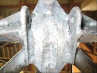
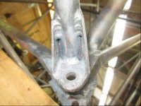
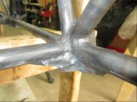
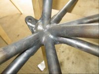
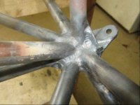
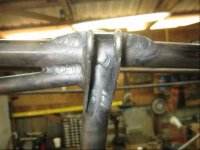
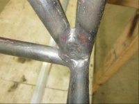
HI Guys, Im back, But you all are probably going to kick me out of the plans built group. This past Sunday I took delivery of a beautifully welded fuselage from Mark. I got a great deal on it and I feel much more comfortable with the welding job. I will be posting more regular again and I want to start by posting a lot of pictures of the beautiful welds on the fuselage. I know when I started welding the tubing kit I needed to see what the welds were supposed to look like. I hope this will be a service to those who are welding a tubing kit.
 
Looking forward to the pictures!! That kit will save you a ton of time and give you the peace of mind you were looking for.
 
If there is anything in particular you want to see Steve just let me know and I make a special effort to get a picutes of it.
 
Here are some pics of the factory welded fuselage
 

Attachments

  • photo5211.jpg
    photo5211.jpg
    61.3 KB · Views: 0
  • photo5212.jpg
    photo5212.jpg
    59.4 KB · Views: 0
  • photo5212.jpg
    photo5212.jpg
    59.4 KB · Views: 0
  • photo5213.jpg
    photo5213.jpg
    61.6 KB · Views: 0
  • photo5214.jpg
    photo5214.jpg
    54.7 KB · Views: 0
  • photo5214.jpg
    photo5214.jpg
    54.7 KB · Views: 0
  • photo5215.jpg
    photo5215.jpg
    59.6 KB · Views: 0
  • photo5215.jpg
    photo5215.jpg
    59.6 KB · Views: 0
  • photo5216.jpg
    photo5216.jpg
    67.6 KB · Views: 0
  • photo5217.jpg
    photo5217.jpg
    46.1 KB · Views: 0
  • photo5218.jpg
    photo5218.jpg
    72.3 KB · Views: 0
  • photo5219.jpg
    photo5219.jpg
    59.9 KB · Views: 0
  • photo5220.jpg
    photo5220.jpg
    65.8 KB · Views: 0
  • photo5221.jpg
    photo5221.jpg
    63.1 KB · Views: 0
  • photo5222.jpg
    photo5222.jpg
    63.2 KB · Views: 0
  • photo5223.jpg
    photo5223.jpg
    60.5 KB · Views: 0
  • photo5224.jpg
    photo5224.jpg
    61.9 KB · Views: 0
  • photo5225.jpg
    photo5225.jpg
    52.3 KB · Views: 0
  • photo5226.jpg
    photo5226.jpg
    55.5 KB · Views: 0
  • photo5227.jpg
    photo5227.jpg
    61.8 KB · Views: 0
more pics
 

Attachments

  • photo5229.jpg
    photo5229.jpg
    59.9 KB · Views: 0
  • photo5230.jpg
    photo5230.jpg
    56.9 KB · Views: 0
  • photo5231.jpg
    photo5231.jpg
    60.7 KB · Views: 0
  • photo5232.jpg
    photo5232.jpg
    58.8 KB · Views: 0
  • photo5233.jpg
    photo5233.jpg
    65.9 KB · Views: 0
  • photo5234.jpg
    photo5234.jpg
    61.4 KB · Views: 0
  • photo5235.jpg
    photo5235.jpg
    53.6 KB · Views: 0
  • photo5236.jpg
    photo5236.jpg
    58.9 KB · Views: 0
  • photo5237.jpg
    photo5237.jpg
    55.3 KB · Views: 0
  • photo5238.jpg
    photo5238.jpg
    55.7 KB · Views: 0
  • photo5239.jpg
    photo5239.jpg
    67.3 KB · Views: 0
  • photo5240.jpg
    photo5240.jpg
    58.3 KB · Views: 0
  • photo5241.jpg
    photo5241.jpg
    51 KB · Views: 0
  • photo5242.jpg
    photo5242.jpg
    51.3 KB · Views: 0
  • photo5243.jpg
    photo5243.jpg
    68.3 KB · Views: 0
  • photo5244.jpg
    photo5244.jpg
    50.4 KB · Views: 0
  • photo5245.jpg
    photo5245.jpg
    58.2 KB · Views: 0
  • photo5246.jpg
    photo5246.jpg
    77 KB · Views: 0
  • photo5247.jpg
    photo5247.jpg
    79.4 KB · Views: 0
Hi Guys, I have an update, I got my shock struts assembled. I had to come up with a special little rig to compress the die spring to get the piston assembly far enough into the cylinder to get the top plug in. If anyone is interested in it let me know.
 
On the 4-Place I use a socket as a spacer, and a bolt with the same thread as the rod end bearing.
 
Dave, Good for you for doing what you feel is safe! That's a big part of building an airplane. I really really curious though; could you share some pics of the welds that condemned your fuselage? I had some welds on my fuselage that I didn't like but the A&P that inspected the airframe before I bought it said they were ok. I had a couple guys come over and they said the same thing, tottaly safe but not real pretty. I couldn't stand leaving them so I ground them out and rewelded.

I'd hate to hear what your friend has to say about Stinson fuselages. They were stick welded :eek: and some clusters look downright scary. But they are 70y/o and still going strong.
 
Hi Whee, I dont have the fuselage any longer. I just left it in Florida. I really don't have the space for 2 fuselages. It wasn't just the welds there were some other issues that I caused in my attempt to weld it. I just look at it as an expensive lesson. There are pictures I have posted in the past. The welds that worried me the most were the ones around the landing gear attach points and the one's at the top of the fuselage where the wing attach points would be. I really feel better about having the factory welded fuselage because I never have any doubts about its safety. And Mark made a good point about it too, and that was that if I ever wanted to sell it I could ask for a higher price since it had a factory welded fuselage. I don't know if you looked at the pictures I have posted of the factory welded fuselage but they look great. I am very pleased with it. And it is soooooo straight, I couldn't believe how straight it was. Ill be making more post when I get more parts from Mark.
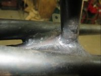
 
Hey Jared, I used a similar set up, but I used a piece of tubing and a check nut on the rod end bearing and washers. I was just wanting to find a way to do it without damaging anything.
 
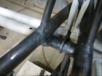
Hi Guys, I finally have some progress to report, this is the first time on a long time Ive had a chance to work on my plane. ATT is trying to work me to death I think. Anyway I got my main gear and tail wheel fitted and bolted on to the fuse. I had to grind a little off the inside of the main gear connection points to get the main gear legs to slid up into the brackets on the fuse. I didn't have to remove very much metal at all either. Also I drilled the holes for the fitting per the plans. With that I would like to promote a product Ive been using. It is the drill doctor, the thing cost me about $150 bucks but it has paid for it self many times over because drilling work hardened metal breaks drill bits very easily. The holes in the tail spring are undersized. Per the plans the holes are supposed to be 5/16 but it comes with 1/4 holes. So now I am the proud owner of many little bitty short 5/16 drill bits.
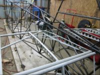
 
Last edited:
Hi Guys, And yet more progress today, its amazing what you can do when you spend 10 hours straight out in the shop. Got the front and rear rudder peddles attached. Have a question about brake calipers, I chose to put mine on the rear of the rotor mainly because I was not able to find any info about which side to put them on. So I just made a command decision I just hope it is correct. If anyone know for sure which side they should be on please let me know. I have pics this time too. Hope you like them.
 

Attachments

  • photo5585.jpg
    photo5585.jpg
    70.7 KB · Views: 0
  • photo5584.jpg
    photo5584.jpg
    79 KB · Views: 0
  • photo5586.jpg
    photo5586.jpg
    60.6 KB · Views: 0
  • photo5587.jpg
    photo5587.jpg
    77.7 KB · Views: 0
  • photo5588.jpg
    photo5588.jpg
    71 KB · Views: 0
  • photo5589.jpg
    photo5589.jpg
    71.5 KB · Views: 0
  • photo5590.jpg
    photo5590.jpg
    74.2 KB · Views: 0
  • photo5591.jpg
    photo5591.jpg
    88 KB · Views: 0
  • photo5592.jpg
    photo5592.jpg
    71.5 KB · Views: 0
HI Guys, Progress today, I got the vertical stab attached to the tail post. I wanted to show a clamp I made for the tail post. It is a splint of sort to keep the tail post straight while I welded the ribs to it. The splint is made from a length of 3/4 inch angle with a piece of square tubing with one side cut off welded to it. Here is the procedure I used to get the vertical stab welded on, I first tack welded the leading edge tube on, then I cut notches the diameter of the tube that the rib would join, then I tack welded the ribs in. After that I fitted and welded in the diagonal tube from the leading edge tube to the root of the tail post. I had to cut a hole in the center rib to get the diagonal tube fitted. You may notice my vertical stab is not offset like in the plans. The reason is that I am using a Corvair engine and it rotates opposite of a regular aircraft engine. I plan to put a trim tab on the rudder or maybe a rudder trim system, the jury is still out of which way I will go on that. Got pix so if you have any questions fire away.
 

Attachments

  • photo5629.jpg
    photo5629.jpg
    89.4 KB · Views: 0
  • photo5630.jpg
    photo5630.jpg
    57.2 KB · Views: 0
  • photo5631.jpg
    photo5631.jpg
    90.7 KB · Views: 0
  • photo5632.jpg
    photo5632.jpg
    90.2 KB · Views: 0
  • photo5633.jpg
    photo5633.jpg
    90 KB · Views: 0
  • photo5634.jpg
    photo5634.jpg
    86.4 KB · Views: 0
Nice work Dave! I found building the fin to be very rewarding. Was one of the first steps that made the fuselage start to look like and airplane.
 
Thanks for the encouragement guys, Im on vacation this week so I hope to get a lot done, ill be posting on my progress.
 
HI Guys, More progress to report today, finally got the horizontal stabs fitted and that pesky little tab the the elevator bearings attaches to welded in. I got the elevators installed as well. I have a full range of motion. As anyone who has installed these you know what a pain it is. Here are the pic.
 

Attachments

  • photo5647.jpg
    photo5647.jpg
    98.6 KB · Views: 0
  • photo5648.jpg
    photo5648.jpg
    53.5 KB · Views: 0
  • photo5649.jpg
    photo5649.jpg
    93.3 KB · Views: 0
  • photo5650.jpg
    photo5650.jpg
    71.9 KB · Views: 0
  • photo5651.jpg
    photo5651.jpg
    82 KB · Views: 0
Hi Guys, More progress today, got the tail wires fitted and the trim system in, still need to finish assembling the trim system, just have the parts fitted together. Ill post more later.
 

Attachments

  • photo5656.jpg
    photo5656.jpg
    58.2 KB · Views: 0
  • photo5657.jpg
    photo5657.jpg
    82.9 KB · Views: 0
  • photo5658.jpg
    photo5658.jpg
    81.8 KB · Views: 0
  • photo5659.jpg
    photo5659.jpg
    81.2 KB · Views: 0
Hi Guys made a little more progress today. I got the elevator trim system drilled and fastened together. I found that my elevators will only go up 23 degrees so I will need to cut the elevator bearing tab loose and move it up some. That is a tricky part to get right. Comment and suggestions are welcome,
 
Hi Guys, More progress today, I got my elevator fixed, it now deflecting per the specs, I also got the idle arm installed. Hope you like the pictures,
 

Attachments

  • photo5683.jpg
    photo5683.jpg
    60.4 KB · Views: 0
  • photo5684.jpg
    photo5684.jpg
    66.5 KB · Views: 0
  • photo5685.jpg
    photo5685.jpg
    69.8 KB · Views: 0
  • photo5686.jpg
    photo5686.jpg
    67.4 KB · Views: 0
  • photo5687.jpg
    photo5687.jpg
    76 KB · Views: 0
Hi Guys, More progress today, I got the trim tabs cut loose from the elevators and got the hinge pins in, I now have functional trim tabs, I also got the front control stick built. Here are the pics
 

Attachments

  • photo5701.jpg
    photo5701.jpg
    86.3 KB · Views: 0
  • photo5700.jpg
    photo5700.jpg
    87.2 KB · Views: 0
  • photo5702.jpg
    photo5702.jpg
    59.9 KB · Views: 0
HI Guys, I have some progress to report today. I got a big start on my control column, I have the front stick built and the front pivot point for the cintrol stick and it is welded to the control column tube. Anyway here are the pictures.
 

Attachments

  • photo5706.jpg
    photo5706.jpg
    59.9 KB · Views: 0
  • photo5707.jpg
    photo5707.jpg
    46 KB · Views: 0
  • photo5708.jpg
    photo5708.jpg
    72.2 KB · Views: 0
  • photo5709.jpg
    photo5709.jpg
    59.9 KB · Views: 0
  • photo5710.jpg
    photo5710.jpg
    51 KB · Views: 0
Last edited:
Hi guys, got more done today. Im working on the control column I have the front half done, have the front stick built, I got the rear stick built and the rear box it goes in built today. I had to build that box 4 times before I got one I could live with. Welding .032 steel to .032 steel is a PIA. So I cheated on the last rear stick box. I used .050 for the narrow ends and overlapped the .030 over the .050 and used the excess .030 as filler. I got much better results. Here are the pics so you can see the progression, from left to right. My final part is on the far right.
 

Attachments

  • photo5744.jpg
    photo5744.jpg
    81.7 KB · Views: 0
  • photo5745.jpg
    photo5745.jpg
    82.4 KB · Views: 0
  • photo5746.jpg
    photo5746.jpg
    82.6 KB · Views: 0
  • photo5747.jpg
    photo5747.jpg
    83.8 KB · Views: 0
Hey Chewie, thanks for the video links, I have watched those video several times and they have really helped my welding. I know about the .030 to .090 as well, when I built my sticks the lower part had that combination of metals as you know. Yes that was a PIA as well. I got it done but is was not pretty. My next steps are welding the rear stick box on the torque tube. I have the pivots welded in the box. How did you set up to make that big hole in the rear box? I was thinking of using a hole saw or maybe just grind it out with my burrs on the die grinder. How did you do it?
 
Actually I don't know, I was just throwing out random wall thicknesses. Truth is I purchased my sticks and related framework from Dallas Shell. I won't show you a picture of the assembly because we will both bow our heads in shame. He's a fine craftsman.
 
Dave

I just clamped the assembly well in my drill press and used a hole saw.

Slow speed and cutting oil is key.
 
hey Brad and Mark thanks for responding to my questions. Brad that is sort of what I was thinking of doing. I have a mill and I can slow the cut to less than 300 RPM. Mark I considered just buying one also but after the fuselage debacle I wanted to see if I could actually build some part of the critter. Hell who knows I may just haul off and buy it after all.
 
Hi Guys, more progress tp report today. i finally got my control column together. My next task is to get it attached to the fuse. Here are the pix.
 

Attachments

  • photo5820.jpg
    photo5820.jpg
    96.3 KB · Views: 0
  • photo5821.jpg
    photo5821.jpg
    93.1 KB · Views: 0
  • photo5822.jpg
    photo5822.jpg
    73.5 KB · Views: 0
  • photo5823.jpg
    photo5823.jpg
    94.2 KB · Views: 0
  • photo5824.jpg
    photo5824.jpg
    78.4 KB · Views: 0
  • photo5825.jpg
    photo5825.jpg
    98 KB · Views: 0
Hi Guys, More progress today, finally got the control column attached to the fuse. I took a little liberty with the front mount as you can see. for me welding straight lines is much easier than welding tube. Here are the pics.
 

Attachments

  • IMG_4588.JPG
    IMG_4588.JPG
    78 KB · Views: 0
  • IMG_4590.JPG
    IMG_4590.JPG
    83.2 KB · Views: 0
  • IMG_4589.JPG
    IMG_4589.JPG
    76.1 KB · Views: 0
Just one comment from me... Shouldn't this control linkage be using castellated nuts with cotter pins instead of nylocks? It's critical to flight, and it moves in such a way that the nylocks could back off... I'm certainly no expert, but that's what my DAR seems to (rather strongly) prefer...
 
HI Jim, im just bolting stuff together for now just to check fitment, Before my inspection and flight all of the hardware will be replaced with new hardware and the proper hardware.
 
Hey guys, has anyone else ran into the problem of the front control stick hitting the cross tube the instrument panel attaches to? If so did you just cut off and inch or 2 of the stick?
 
Dave, I raised the cross member one inch not because I was smart but because my buddy said his knees would not fit, thus all is well. It turns out very helpful even for my 5ft 7inch frame. The leverage is helpful. Stinger
 

Attachments

  • photo5846.jpg
    photo5846.jpg
    1.5 MB · Views: 0
Wow Stinger you read my mind, I was thinking about that but had not asked the question yet. I was wondering about the effect of removing an inch or 2 of the stick on the amount of leverage it would take away from the control pressure. I was thinking with the auto servo trim tabs it probably would not make that much difference. Im about the same height as you so the height of the cross bar is not a problem for me either. How much do the auto servo trim tabs lighten the control pressure loads? I always thought of them sort of as power steering. I also noticed how your panel does not sit on top of the cross bar. Was that to give you more space in the cockpit?
 
I am sure you know the trim tab reduces stick pressure thus less muscle is required .I only have one trim tab because that's what my plans showed plus I had never seen an actual Bearhawk . My LSA has manual trim. My panel sets on top of the cross bar pretty much as plans state but with less height maybe one half inch. Stinger
 
Hi Stinger like the way your panel looks. It is minimum and simple and that is what my panel will be. Im planning on a PFD and a back up altimeter and AS and a tach and engine instruments. I think after I get it flying ill add a transponder. Probably just use a hand held radio to begin with.
 
Hi Guys, I finally have the elevator control linkage set up in my LSA. To me it is a mile stone, I can now sit on my airplane and make airplane noises. I think my next step is to build my seats. But first I need to tweak some other things im not very happy about. Ill include more pictures soon.
 
Hey Guys wanted to ask if anyone building the LSA is using square tubing to build the door and window frames? I think using square tubing would make it easier to build? I noticed that sqaure tubing is used in the Patrol.Looking for comments or suggestions.
 
Bob has changed the factory to round tubing for doors and windows for the large part. It weighs less for sure and Bob thinks it is easier to install the aluminum/plexi on it although not all builders agree with that. Mark
 
Thanks for the input Mark, Ill probably just do what you always say to do "stick with the plans". Here are some pictures of my latest progress,
 

Attachments

  • photo5930.jpg
    photo5930.jpg
    1.4 MB · Views: 0
  • photo5931.jpg
    photo5931.jpg
    1.4 MB · Views: 0
  • photo5933.jpg
    photo5933.jpg
    1.4 MB · Views: 0
  • photo5932.jpg
    photo5932.jpg
    1.5 MB · Views: 0
Back
Top