Engine Trouble

Nev

Quick-build 4-place B #25
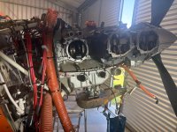
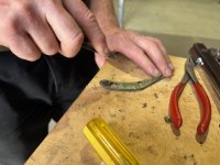
We attended a Bearhawk fly-away last week, and while returning home over water between the islands experienced a loss of engine power. We made a precautionary landing and discovered 3 cylinder studs had sheared off above the #4 cylinder. Several of the remaining ones were loose.

My reason for mentioning it here is that with the benefit of hindsight there were some early warning signs that I had missed, and that knowledge might benefit others. It's not a Bearhawk specific issue, but rather an engine issue. Mine is an IO540 that was rebuilt specifically for my Bearhawk.

It now appears that the sequence of events was that the studs probably sheared some time earlier, resulting in a small oil leak. We subsequently also found the left exhaust cracked through in several places.

The final straw was actually the spark plugs failing on the affected cylinder with accompanying rough running, power loss, CHT & EGT indications decreased abruptly as the precursor to the precautionary landing.

Several studs were also found to be loose on other cylinders, so we will be checking all of them and torquing to Lycoming specs.

Next time I'll be paying more attention to any oil leaks no matter how small, and also casting an eye over those cylinder nuts which are visible.

Click image for larger version  Name:	E99A02E5-4B40-4FBB-AF8C-0F48A0B8C596.jpg Views:	28 Size:	289.9 KB ID:	92911

Click image for larger version  Name:	E99A02E5-4B40-4FBB-AF8C-0F48A0B8C596.jpg Views:	28 Size:	289.9 KB ID:	92911

Click image for larger version  Name:	0855AF0C-E5F6-46AE-9E97-AD7499CF4F85.jpg Views:	29 Size:	702.8 KB ID:	92914

Click image for larger version  Name:	0855AF0C-E5F6-46AE-9E97-AD7499CF4F85.jpg Views:	29 Size:	702.8 KB ID:	92914

Click image for larger version  Name:	0855AF0C-E5F6-46AE-9E97-AD7499CF4F85.jpg Views:	29 Size:	702.8 KB ID:	92914

90 minutes earlier in the flight, unaware of the issue.

Click image for larger version  Name:	0A30F742-7F77-496E-B51B-505312F23B26.jpg Views:	0 Size:	276.2 KB ID:	92924
Flight track from Gisborne across Hawkes Bay and Cook Strait. We landed at Kaikoura on the east coast of the South Island.

Click image for larger version  Name:	CCD81127-7213-4A61-9DF1-829629CA4DA8.jpg Views:	0 Size:	155.5 KB ID:	92925
 
Last edited:
Sorry to hear about this Nev. Glad everyone is OK.

Certainly, it would appear that under-torqued nuts on those studs was the problem. It explains everything you've seen, neatly.
 
Last edited:
Glad you had a safe landing Nev and everyone is safe. I appreciate you sharing the pictures and your experience. Thanks for being a vigilant safety ambassador. Hope the repairs go well and you are back in the air soon.
 
Last edited:
  • Like
Reactions: Nev
Nev. A failing engine at 820ft over Cook Strait is not a happy scenario. Pleased to hear that all ended well.

Just off to the hangar to check my studs and exhaust.
 
Glad you’re safe Nev!

Is that some sort of black sealant on the cylinder base? Can’t see it clearly but it looks like remnants of black rtv type sealant on the edge of the base. Also looks like it’s squishing out of the neighboring cylinder. Hope I’m wrong, that’s a serious no no and would necessitate removal of all cylinders to clean that stuff off and install the cylinders properly.

edit for clarification: If that is some sort of sealant on the cylinder bases then you know the cause of your loose and broken cylinder studs. There should be nothing between the cylinder base flange and the case. Sealant or even paint will eventually cause the studs to loosen and fail.
 
Last edited:
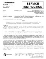
The seriousness of this can not be overstated, the good outcome was a function of Lady Luck smiling at the right time and some good decision making.

A real heads up for the rest of us to pay attention to any oil leaks and preflight check those studs that can be seen.

I think Whee raises a really good point too.

Looking forward to seeing you back in the air Nev.
 
Ho many hours does this engine have on it? As I recall, this is a recently overhauled "Bob" engine. You should not be having these issues at this point, I'd think. Have you talked to Bob about this?
 
Glad to hear everyone is safe! Thank you for sharing your experience as it is a good reminder for all of us to look beyond the small things we may find during pre-flight and ensure that there is not a bigger issue.
 
  • Like
Reactions: Nev
Were any of the nuts on the through-bolts loose? If so, that can lead to bigger issues in the bottom end (case fretting, spun main bearing(s), etc).
 
  • Like
Reactions: Nev
Thanks for your kind words everyone.

Whee - the engineers noticed a contaminant on the cylinder flanges too. The #4 & #5 cylinders have been taken to South Air in Dunedin for inspection and crack testing. They will decide if they can go back on the engine.

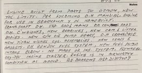
Mark - the engine has 361 Tachometer and 458 Hobbs. I spoke to Bob yesterday and he was very helpful. Bob said they use a torque of 60 ftlbs on the large studs and 30 ftlbs on the smaller ones. He felt the Lycoming specc'd torque of 50/25 ftlbs was not quite enough.

bkyser - some of the remaining nuts were loose, but the studs/ through bolts were all tight. We had to remove the #5 cylinder to extract one of the through bolts. We found it tight and secure, but it requires replacement due to the #4 (left side) end being sheared.

The oil filter is being removed and checked today, and the remaining cylinders are being Boroscoped.
 
Bob said they use a torque of 60 ftlbs on the large studs and 30 ftlbs on the smaller ones. He felt the Lycoming specc'd torque of 50/25 ftlbs was not quite enough.

This seems like something you shouldn't second-guess engineers on. Torquing applies a calculated "stretch" or elastic deformation to a fastener, and this "stretch" has a profile associated with it that I can only think is to maximize retention. I know Bob is a mechanical engineer and I'd like to hear his justification of that change.

Maybe time for some torque seal?
 
Last edited:
I think this highlights a point discussed on another thread.

An experimental engine is exactly that, it’s not a Lycoming that is overhauled by an uncertified organisation, although that is the misunderstanding that a lot of folks, me included, have had.

When I had my experimental engine issues my mindset was wrong. I expected an overhauled Lycoming engine that included Lycoming recommended practices with respect to RTV use, Torque values, parts compatibility etc. It was an eye opener to me that that wasn’t the case.

I’m not saying that it’s wrong to do those things on an experimental engine, it’s just wrong to think that an experimental engine will or must be assembled to a certified standard.

My understanding is (and I’m not suggesting that this is the case here) but if for example RTV is used where it’s not usually recommended, an increased Torque on the bolts might be seen as an appropriate action without full exploration of the unintended consequences. Whereas in certified world that would have to be a rigorously tested procedure that was shown to work consistently before being adopted.

Nev’s experience should be a wake up call for all of us.

I think we all need to be vigilant and monitor our engines for weeps, leaks or changes.
 
Thanks for your kind words everyone.

Whee - the engineers noticed a contaminant on the cylinder flanges too. The #4 & #5 cylinders have been taken to South Air in Dunedin for inspection and crack testing. They will decide if they can go back on the engine.

Mark - the engine has 361 Tachometer and 458 Hobbs. I spoke to Bob yesterday and he was very helpful. Bob said they use a torque of 60 ftlbs on the large studs and 30 ftlbs on the smaller ones. He felt the Lycoming specc'd torque of 50/25 ftlbs was not quite enough.

bkyser - some of the remaining nuts were loose, but the studs/ through bolts were all tight. We had to remove the #5 cylinder to extract one of the through bolts. We found it tight and secure, but it requires replacement due to the #4 (left side) end being sheared.

The oil filter is being removed and checked today, and the remaining cylinders are being Boroscoped.

Not to start a criticism of Bob, but if your logbook entry has the words "as per the Lycoming Overhaul Manual", and he's knowingly over-torquing the cylinder hold down studs, yeah, I think that's an issue. Lycoming is the authority here if he's rebuilding an old Lycoming engine.
 
  • Like
Reactions: Nev
Agreed, if your logbook entry says that then you should be able to rely on the Lycoming standard being met.
 
Further to this conversation I’ve asked a retired engineer to explain how bolt torque works with respect to engines.

I am unqualified and keen to learn and understand, hopefully a qualified forum member can confirm or correct his view.

His position is that engine bolt torque is critical. Reason being that the bolts and the case and cylinder flanges are made of different materials and therefore have different expansion rates so when your engine gets hot the tensile load can be amplified pinging the heads off the studs.

The combination of the increased tensile load caused by the heat expansion and the reduction of tensile strength of the bolt due to thermal material strength degradation poses a significant risk.

That all sounds logical but as an unqualified and uneducated metallurgical chap like myself it would be good to have an experts view.
 
It's quite unintuitive. Bolts experience stress in an interesting way.

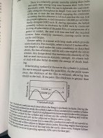
If a bolted connection is torqued up tight, so the preload is higher than the stresses the bolts are experiencing, then there's is very little cyclic stress or strain inside the bolt when the stresses are applied and removed (generalizing dangerously to make it easy to explain). This means the bolt doesn't really experience stress cycles to the same degree. Its almost like a properly torqued bolt is immune to stress, up to a certain point.

As you can imagine, cyclic fatigue is a huge factor in internal combustion engines.

As preload in the bolts (or studs and nuts) is lost, they experience stress and strain with each firing of the engine, this is a huge problem. From this point onwards, failure is a ticking clock, depending on the largest "critical flaw" (biggest micro crack) leftover from manufacturing. Once the stress / strain cycles reach tens or hundreds of millions, the cracks will have grown large - to the point the bolts cannot hold the stress any longer, and they snap.

At some point during this process, the remaining fasteners may also be overloaded, and the problem spreads.
 
A clarification here. Studs and through-bolts are different things and are installed in different parts of the engine. I think we're at risk of confusing the two, for some readers' benefit. If I understand the above posts, the concern is case fretting / bearing issues, which comes from through-bolts which hold the case halves together.
 
Battson. Yes, some of the cylinder hold down nuts are on studs and some of them are on through bolts. The through bolts provide the required clamping force for the main bearings. If an engine is operated without the proper torque on one or more through bolts, bearings can shift (spin) and the cases halves may fret.
 
Last edited:
One of the thru bolts was sheared off, on the side that it is threaded into the block. So we had to remove the opposite cylinder to extract that through bolt. They've opened the oil filter and fortunately found it clean.
 
My experimental engine Logbook entry was similar, new cylinders etc, except they weren’t.

The important thing in my mind is that we need to be vigilant and keep a close eye on our engines. Certified engines can fail too.

Knowing what to look for and what the warning signs are is important to us all so please keep sharing the info!
 
The important thing in my mind is that we need to be vigilant and keep a close eye on our engines. Certified engines can fail too.

Knowing what to look for and what the warning signs are is important to us all so please keep sharing the info!

How can we make this easy to access, and convenient. What items should be on the list?

To be specific in the case of broken studs. These probably failed because Bolts are elastic and the ignition/power stroke event places them in a high tension 40 times a second. I think The stretch - compress stops with a clamping pressure higher than what the compression forces are on the joint or fastener. so i think if they are stretched a bit every event due to a sealant on the cylinder base or a less than adequate clampdown by inadequate torque on the nuts, then they fail due to fatigue.

So, how can I see if mine are torqued properly? I think I need a special tool for my stud bolts that are like Nev's in post #1. Edit. Here is a link to Narrow Deck Cylinder wrench. Will the failure mode of hardware that is not torqued to spec just stretch the and cycle and fatique itself to death without giving any warning? Will Torque Seal indicate a loosening of the bolt?

Simple checks like that and understanding failure modes do more than just make us feel good.

Edit. Here is a link to Narrow Deck Cylinder wrench. https://www.aircraft-tool.com/Detail?id=6494-SET​​
 
Last edited:
I built my 0-360 angle valve 6-7 years ago and recently had reason to torque the case nuts. 60 foot pounds was in the hard drive of memory. I think the AME who helped me torque the rod bolts mentioned to use 60 lbs for the case.
I went through my OH manuals and couldn’t find anything that indicated more than 50 ft lbs for the cylinder base nuts and nothing on line researching Lycoming SI’s. It’s obviously something being done in the field without mention from the manufacturer.
Parts being used for experimental engines CAN have an abundance of unknown hours. During OH, the through bolts are suppose to be replaced but there is no requirement for the short case studs to be changed out. I believe these studs only have a life of X amount of hours considering the cycles of stress. Engines for their first or second OH should be safe but there are parts out there with over 10k of hours accumulated and nothing more is considered about the high cycled studs being put back into service. My 2 cents worth…..
 
Will the failure mode of hardware that is not torqued to spec just stretch the and cycle and fatique itself to death without giving any warning?
Will Torque Seal indicate a loosening of the bolt?

Yes, and no, respectively.

Yes: Short of using NDT techniques, you aren't going to find cracks in a torqued in-service bolt unless the bolt fails, or you regularly disassemble and look for them - which is inadvisable, in this case.
No: The bolts don't have to rotate to loosen, and rotating doesn't always mean they got looser (although it would probably indicate they are loose!)

Retorquing a bolt (or stud and nut) that has already started to literally "stretch" (i.e. plastic deformation) or crack doesn't help your situation either, in fact it will probably make it worse. Once the cracking process has started and the crack has grown a meaningful amount, you'd need to reduce the stresses to stop it continuing to grow (which isn't going to happen in this use-case).

As far as I can tell, the main thing is getting the engine assembled correctly in the first place. There is a lot to know here, in terms of doing it correctly, so I won't dare to summarise the Lycoming manuals. But you need to know what you're doing e.g. dry vs wet torque, etc., which is why I choose to get my engine serviced exclusively by experienced certified professionals. I don't know enough about it.

Beyond that, I think looking for the signs and symptoms of impending failure is the best bet. As Nev has already said. e.g. Check your filters, recognize changes in vibration, oil consumption / leakage, exhaust emission products, engine temperatures, always borescope cylinders once a year, monitor plug wear, fuel pump pressures at run-up, etc. the list goes on and on. Know your aircraft intimately and you'll have the best chance of seeing it coming.

I fully take Grant's point about experimental engines. As Nev's experience makes painfully clear, whether you are flying over water, everglades, forests, mountains, scrublands, a city, vineyards... etc. There are not always great options available, if you need to land suddenly. This is another reason why I get some peace of mind from the -540 engine and other 6-cylinder engines, they are well balanced and often keep running "well enough" if a cylinder fails somehow. Of course we all have a range of stories and experiences, so generalising is dangerous.
 
Parts being used for experimental engines CAN have an abundance of unknown hours. During OH, the through bolts are suppose to be replaced but there is no requirement for the short case studs to be changed out. I believe these studs only have a life of X amount of hours considering the cycles of stress. Engines for their first or second OH should be safe but there are parts out there with over 10k of hours accumulated and nothing more is considered about the high cycled studs being put back into service. My 2 cents worth…..

I am not so sure, I mean anything is possible, but if I recall correctly:

Cyclic fatigue has a critical stress limit. Below that stress limit, cyclic fatigue cracking cannot occur as the crack cannot grow, because the stress isn't high enough. Crack growth is a function of the critical flaw size (largest micro-crack), as well. If the crack is growing, it will not last very long on an engine, 10^8 stress cycles is an average fatigue life for instance - which is about 700 hours of flight time, But it can vary through a wide range depending on the stress level and crack size. The rate of cycle accumulation is just too fast for parts to last for along time on an engine, if fatigue cracking processes are in place.
 
Nev,
What bad luck for this to happen, but good luck and good airmanship got you and your family safely on the ground.
Interesting reads on all the posts and a good jog to remind us all to look for even the smallest tell-tales.
 
  • Like
Reactions: Nev
How can we make this easy to access, and convenient. What items should be on the list?
So, how can I see if mine are torqued properly?

Brooks, this has been on my mind too. With the benefit of hindsight I can now see there was one warning sign that I missed, namely a small oil leak that appeared several weeks beforehand. I had previously had an oil leak from the prop governor, so I attributed it to that, not realizing that it was a new leak. Secondly, I'll now be taking a look at the cylinder studs/nuts where visible on the preflight.

Once we get the aircraft airworthy, I'll fly it back to my home airfield, and at the recommendation of my aircraft engineer and the engineers at South Air in Dunedin we will be inspecting the other cylinder flanges for contaminants, and torquing them to Lycoming specifications. This will take a day or two to accomplish, but given the flow on effects of the past week it should provide simple peace of mind.

If you and your engineer wanted to perform a similar check on your engine, and if it was still on the workbench during the build process, then it's relatively straightforward to do this and would probably take half a day. If the engine is already installed and flying, then it requires the removal of the baffles and a few other components - which is what we will be doing next week to mine. The baffles also need to be removed to gain access for the specialist tool you mentioned.

As I've discovered, the downstream effects of such an incident are not much fun and there's a fair amount of stress involved. My aircraft was tied down outside for 5 nights at an airfield 3 hours drive from home. Gale force winds loosened the control locks and have apparently done some further damage that we need to quantify. Additionally, my flying companion Sarah has lost her enthusiasm to fly in my aircraft. The overall cost I haven't begun to calculate, but fortunately it's only financial. No one was injured, and no one died.

If I had known of these issues beforehand, I would have gladly spent a day rectifying them in order to avoid the events of the past week.
 
Last edited:
Brooks, this has been on my mind too. With the benefit of hindsight I can now see there was one warning sign that I missed, namely a small oil leak that appeared several weeks beforehand........ I'll now be taking a look at the cylinder studs/nuts where visible on the preflight.

Lycomings leak. I don't know. Do the stud nuts reveal anyting to us? I really dont know. I want to know. I like a good preflight!!! I love our engine cowls .... that we can see them!

To pick up a new small leak and find a broken stud, the nut may not have even been loose. I don't have enough skill to pick that up. I have an idea....Seems to me like a vibration meter might be handy. One could know his engine's base vibration level, document it and other parameters once every 25 hours or so, then watch and see if the vibration changes over time.

Nev, Others may not know that you probably did engine trend checks in your career, where we documented all engine parameters (including vibration on turbine aircraft) in cruise flight so our Maintainers could watch and see engine wear and tear trending over time. For example, A bird strike might not have been noticed, but the vibration might spike up to reveal that something suddenly changed.

If a single stud broke, I suspect a vibration indicator might spike up (measurable, but yet small enough I might not feel or notice it.) Someday our engine monitors might include this data point.

I want to just trust my engine builder. I don't want to tear into it, tearing off all that baffling, to verify the engine that was built iaw Lycoming Manuel. Yet I feel your experience and the results it has had on your companion. Thats significant to me.

https://www.amazon.com/HOJILA-Digit...16413791&sp_csd=d2lkZ2V0TmFtZT1zcF9hdGY&psc=1
 
  • Like
Reactions: Nev
Battson is always so at explaining things is ways most folks can understand. Wish I had that knack.

IMO, the best way to prevent this from happening is to check your cylinder bases for signs that they were assembled with sealant on the base flange. Typically this is easy to see with a visual inspection. If they were assembled with sealant on the flanges then your engine was not assembled in accordance with the Lycoming or Continental overhaul manual and you are at high risk of loosing preload on the studs/through bolts which will lead to their eventual failure.
 
I wish I had something, gained from experience, to add. But my only "add" is that Lycoming and Conti have changed so much, over so many decades, what is real any more? What is the bible of their engines? We exist in a tiny market, with tiny manufacturers, that are trying to stay in business. Lycoming recommends something now that they didn't for the last 50 years. So they were wrong for 50 years?


Does anybody at Lycoming or Conti even know the standards by which the original engines were designed or built? How many AD's have come out over the decades for their screw ups?

The best we, as users, can come up with are "best practices". What is that?

I haven't worked my way up to the novice level yet.
 
  • Like
Reactions: Nev
I wonder how a vibration monitor would go on a piston engine. They were certainly the biz on the turbines and jets. Maybe someone has tried it.
 
Battson is always so at explaining things is ways most folks can understand. Wish I had that knack.

IMO, the best way to prevent this from happening is to check your cylinder bases for signs that they were assembled with sealant on the base flange. Typically this is easy to see with a visual inspection. If they were assembled with sealant on the flanges then your engine was not assembled in accordance with the Lycoming or Continental overhaul manual and you are at high risk of loosing preload on the studs/through bolts which will lead to their eventual failure.

Check both sides of the cylinder flange too - between the flange and the hold down plates which is where sealant was found on mine.
 
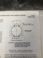
Glad you made that landing successful. Ive never seen the cyl base studs crack on a lycoming like these and I have years of maint experience on lycomings. Because it is a narrow deck eng make sure when you are reinstalling the cylinder hold-down plates to use use shims as per the manual attached.
 

Attachments

  • photo17308.jpg
    photo17308.jpg
    1.7 MB · Views: 0
  • photo17309.jpg
    photo17309.jpg
    2.4 MB · Views: 0
I checked mine today and they look OK. I broke in my engine on the ground, and now the prop doesn't cycle, which it did in the beginning. Pulled the filter, and there were bits of red sealant. Not large, maybe 1 - 3 mm. Taking apart the Johistral governor tomorrow.
 
Hmmm … red RTV rings a bell, as does a blocked oil gallery and a wreck bought off the insurance company of a plane I once flew. Be careful.
 
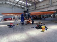
Finally got my Bearhawk home today. My engineer Kevin and I got an early start at 5am, drove up and removed the sheared studs, and replaced the two cylinders. We changed the oil back to straight 100. Also found several very loose nuts and bolts on the engine - the vibration had taken a toll, and we spent a while checking everything once it was back together. I've started running the cylinders in on the way home. Once thats finished we will clean the remaining 4 cylinder flanges and complete an annual on the aircraft.

Click image for larger version  Name:	A0B96C12-79B6-4D79-A32B-2B5EBDA2815F.jpg Views:	0 Size:	2.09 MB ID:	93046

Click image for larger version  Name:	E2FE62B6-1006-4C75-802D-99C631689BE4.jpg Views:	0 Size:	2.31 MB ID:	93047

Click image for larger version  Name:	3AFBFA9D-32DF-4CC6-9AA1-D52ABEB7C2DD.jpg Views:	0 Size:	2.45 MB ID:	93048

Click image for larger version  Name:	4D7CB818-5654-4EE8-AF9E-6F8B52BC5AEF.jpg Views:	0 Size:	1.95 MB ID:	93049
 
Last edited:
Looking all over the engine, the only place it was visible was the accessory case. Vacuum pad and one other I can't identify off the top of my head. Oil sump, case, etc not visible.
 
Congratulations Nev on a good all around job getting it down safely without any incident and getting it back to base after repairs.
Because of some recent cylinder trouble, I have been researching engine/cylinder break-in procedures at length, and cannot find anything concrete on gospel power settings quoting a reliable source. I am only asking this for the purpose of educating myself and for no malicious reasons. I see a power setting of 28” and 2300 rpm on the efis. I gather that is wot and a low prop setting at 1300’. I would like to know if there is any supporting documentation to use these numbers. I have walked away from the computer with the idea I had the right numbers of 25” at 2500rpm below 3000’ with variations on either side for proper initial ring seating. Friends of mine with recent OH engines have been told by the shop to set up their ground adjustable props for 2200 static rpm and run it at wot. Again I can’t find anything that supports this but looks similar to what your doing. I’d appreciate any help here. Thanks
 
Thanks Steve. Yes it was WOT at 2300 RPM. Those settings are not based on anything Gospel or scientific, just lots of reading and chatting with others, and my previous engine run-in went well. I think my engineers words were "don't baby it - best to give it some abuse on the way home".

First time around for run-in I used ROP and around 2400 RPM. Normally I cruise LOP at about 26" and 2200 RPM. Yesterday I wanted to keep the ICP relatively high, but without the cylinders getting too hot. It seemed easier yesterday because the other cylinders are already run-in and so I was able to keep cylinders 4 & 5 below 210c (410f).

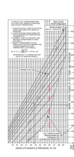
The chart below from the Lycoming manual shows that the power setting is within the recommended envelope. The red dashed line is for my normal cruise operation, and 28.5" MAP is on the edge of the envelope at 2300 RPM.

There's others on the forum who might chime in here with a lot more specific experience than I have.

Click image for larger version  Name:	9D704DBE-A39B-4440-BF66-9B3EC8A10548.jpg Views:	0 Size:	482.7 KB ID:	93055
 
Last edited:
Because of some recent cylinder trouble, I have been researching engine/cylinder break-in procedures at length, and cannot find anything concrete on gospel power settings quoting a reliable source. I am only asking this for the purpose of educating myself and for no malicious reasons. I see a power setting of 28” and 2300 rpm on the efis. I gather that is wot and a low prop setting at 1300’. I would like to know if there is any supporting documentation to use these numbers. I have walked away from the computer with the idea I had the right numbers of 25” at 2500rpm below 3000’ with variations on either side for proper initial ring seating. Friends of mine with recent OH engines have been told by the shop to set up their ground adjustable props for 2200 static rpm and run it at wot. Again I can’t find anything that supports this but looks similar to what your doing. I’d appreciate any help here. Thanks

Based on research we did dozen years ago, for a Lycoming -540 engine, we arrived at 75% power (or more) for engine break-in.
Given the elapsed time, I can't recall where we sourced that from, but we have it documented in our test flying procedures. I thought it was authoritative, but I can't be sure sorry. ​

Which settings you choose, to achieve your desired power setting, are surely dictated by the Lycoming operating manual, the engine's performance (temperatures mostly), among a range of other factors. Some of the main considerations are the need to keep the engine below the redline CHT, and the maximum allowable difference in MAP and RPM.

I see you've heard people using 2200 RPM and WOT. That would be pretty close to the allowable limit, depending on the MAP the specific configuration is achieving. In my aircraft, that would be beyond the allowable limit at 1,000ft and just within the limit at 3,000ft. If engine temperatures allow, a lower MAP and higher RPM may be a lower risk option.
 
  • Like
Reactions: Nev
Thanks Nev. That’s what I needed to see and hear. I am so old that when I hear high over square numbers I cringe! Have about 3000 hours sitting behind Conti 520’s and it was beaten in to my skull by the company engineers “square for climb and one inch off in cruise rpm. Helped take two engines to tbo without a cylinder change. Also no leaning below 5000’. These were factory OH engines but of course, Continental. Different beasts.
 
  • Like
Reactions: Nev
There are a few IO540 powered aircraft that are rated at 235 hp (Maule and Cherokee come to mine) that limit HP by limiting max rpm. Off the top of my head I can't remember the exact rpm, but 2350 or 2375 comes to mine. So seal level MP and those max rpm seem to be OK.
 
Reconfigure the manifold pressure to show hectopascals and the remainder of your oversquare concerns will be gone.
 
Our RV-4 barely exceeds 2200 rpm on take-off and climb out. ...WOT, of course. Need to get above about 100 kts to get the rpm higher.
 
Here's another version of the chart posted earlier on this thread, showing that the lowest RPM for operating at 28" is 2200 (noting it's actually for a carburetored engine).
Below that is an excerpt from the Lycoming website. Link to the full webpage HERE.

Link to Lycoming service bulletin on how to run the engine in HERE.

Click image for larger version  Name:	5C54AB65-0A82-412E-8D05-13CA6FF435E9.jpg Views:	145 Size:	442.3 KB ID:	93077


Click image for larger version  Name:	5C54AB65-0A82-412E-8D05-13CA6FF435E9.jpg Views:	145 Size:	442.3 KB ID:	93077


5E985E95-55D8-4ABC-85FF-99720B4D9CB3.jpg
 
Last edited:
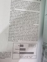
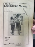
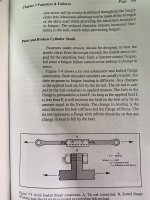
Sky Ranch Engineering Manual

We learned a few more things today. My engineer Kevin dug out an old manual that he had and found the section titled "Paint and Broken Cylinder Studs". It appears that it is a known issue, and definitely a no-go item in the aircraft engine industry. Needless to say that finding this information stated so clearly in an old aircraft engine manual has raised some serious questions in our minds.

It appears at the very least that we will need to replace the remaining 5 studs on the #4 cylinder, which necessitates removing both #4 & #5 again.


C0932CD8-8D0C-4FC4-9D40-559BAC5A8FF2.jpg

E5DE3D73-B974-49F5-97CD-F77ED2DCA8D5.jpg

549BAB04-A00B-449C-9DAF-CC3B4444947D.jpg

A834382E-9492-438D-9212-2E6283361932.jpg
 

Attachments

  • AE4C5367-2CAE-419F-BC57-A2995A3F4F12.jpg
    AE4C5367-2CAE-419F-BC57-A2995A3F4F12.jpg
    2.4 MB · Views: 0
  • 35C5785F-968A-4BDB-9E7B-C0549ABB2720.jpg
    35C5785F-968A-4BDB-9E7B-C0549ABB2720.jpg
    743.3 KB · Views: 0
  • 35EB27BE-5A0E-46FE-895A-F2EF6847A378.jpg
    35EB27BE-5A0E-46FE-895A-F2EF6847A378.jpg
    2.6 MB · Views: 0
  • DAB6C348-31A4-4164-AADA-D42898DBB504.jpg
    DAB6C348-31A4-4164-AADA-D42898DBB504.jpg
    2.7 MB · Views: 0
  • 5CEAFB7B-1941-4414-A4DE-D8AB733FA8A0.jpg
    5CEAFB7B-1941-4414-A4DE-D8AB733FA8A0.jpg
    2.7 MB · Views: 0
  • 25247BDC-C48D-4172-86D2-6C3891FD8F53.jpg
    25247BDC-C48D-4172-86D2-6C3891FD8F53.jpg
    2.9 MB · Views: 0
Thanks for posting Nev!
I have been negligent in not checking into the BH Forums as much as I should. Too busy flying and having fun doing it. To be completely honest, I was was enjoying being ignorantly bliss!
Now I have been educated a bit and need to determine best path forward. This is my first Lycoming engine and I have learned a lot but have a long ways to go. So if you offer advice, type slow so I can understand.:rolleyes:

I basically have the same engine, just no "I" (carbureted). One of Bob's engines. Has been in service 4 years now with 670 hours. Just started to notice small oil weeps around cylinder bases on mostly #4,#5,and #6. When I consult more experienced Lycoming guys, the basic response is that the "L" in Lycoming stands for leaks. I have been very successful at keeping the inside of the cowling spotless so I notice even the smallest weep.

Got a condition inspection on the near horizon and looking for some advice on how to proceed and make sure I understand all the information shared so far.

Given the "Experimental" tag on our engines and this information shared by Nev, I think it would be prudent to remove the baffles and other interfering components and do a torque check of all the cylinder base nuts. If they all meet the Lycoming torque specs, smile and put it back together. Probably should be done every 500 hours?

If even one is loose, then what? If I have a correct understanding pre-stressed vs load stress from the info shared in this thread then re-torquing a base stud nut or through bolt may even accelerate a failure. If I find a base bolt not to torque is the answer to pull all the cylinders, clean the bases of any RTV and reassemble? I think this is what I understand to be Nev's course of action. Does that sound reasonable? On the bright side, this would be an excellent opportunity to ream the exhaust valve sleeves and lap the exhaust valve seats. Just to clean things up.

There is a delicate balance in being proactive and not inflicting further harm. Interested in any advice, please be gentle.

Nev, on that suspected governor oil leak. If you haven't located the source of the leak, check that plug bolt on the nose of the engine for the governor drive shaft. Use the borescope, it is deep behind the starter ring. I had a gasket leak there that needed to be replaced due to a developing leak. Gotta pull prop and remove starter ring to access.

Also I do have a question Nev. You mentioned pulling an opposite cylinder to replace damaged through-bolt. Isn't there an o-ring seal at the case split that can only be accessed by splitting the case? Any concerns there? Are through-bolts routinely replaced when cylinders are installed without splitting the case?
 
I had a similar experience with onset of oil leaks as the engine ages. I suggest finding the source of the oil leaks and resolving them, or at least determining whether they are cause for concern.

Common places for oil to escape are the pushrod cover seals, cylinder head gaskets (often comes loose, tighten screws), oil return lines (both ends - search for my earlier post about the shoddy flares I found), etc.

Oil isn't supposed to leak out of the engine... rather than accept it and move on, I think it's worth pursuing. P.S. I have never heard the "Lycoming's leak" comment. Sounds like an easy excuse ;)
 
I agree with Battson. Finding the source of the leak and making an informed decision on how to manage it is critical.

This has been a great thread from a learning point of view for those of us with limited knowledge.
 
Was the paint/sealant just under the base of those plates, or also at the base of the cylinders themselves?
 
Thanks. Agree with all that. The challenge I face is to listen CAREFULLY when the plane is talking to me. It is easy and often the initial response to rationalize away an issue. Been guilty of that. I have a couple of suspect pushrod shroud cover gaskets. A suspect oil return line. My head gaskets are good. I check those and tighten screws every oil change. I want to emphasize that I'm just in the weep stage mostly. Nothing that I would classify as a leak. I've got a few of the cylinder base bolts that look like the source of some weeps.
Today I did check of few of the cylinder base bolts that I could access with a torque wrench and they were at least Lycoming torque spec.

So my current plan, so far just thinking about it today:
  1. Document and ID all weeps, seeps, and leaks with pictures. Most will be borescope pictures.
  2. Clean all weeps, seeps, and leaks.
  3. Fly and monitor every 5 hours. Document with pictures.
  4. Take action as needed to eliminate leaks.
  5. If I reach condition inspection, remove baffles, exhaust and any other hardware to check the torque of each cylinder base bolt per Lycoming spec.
  6. If any nut/bolt less than Lycoming torque spec, remove cylinders to inspect, clean, re-gasket and reinstall.
  7. if the cylinders come off, I'm gonna lap the EV seats and ream the EV sleeves. Just to clean 670 hours of lead off.
If the cylinder base nut/bolts are the source of the weeps, I don't know of any remedy except to remove the cylinder and clean the metal face flanges. Any other recommendations on that?

Open to any and all suggestions. Fly safe!
 
  • Like
Reactions: Nev
Battson,
Could you give me a better lead on the post for the oil return line leaks. I've done a few searches and come up empty.
thanks
 
John Bickham Regarding the oil leak from my Prop Governor, there was a bulletin about it from 2016. I had it serviced in July, and knowing what I know now I think that problem has been fixed. However the oil leak from the cylinder flange fitted neatly time-wise with the governor leak, so I attributed it to the governor not being repaired properly and didn't search further at that time.

We didn't find any evidence of paint or contamination between the cylinder flange and the crankcase. That area appears to be clean. Because of this we don't plan to remove other cylinders unnecessarily.

We did find very visible evidence on the outside face of the cylinder flange, and under the hold-down plates. It appears that this is probably the cause of the problem. Fortunately, thats easier to access and doesn't require the removal of the cylinder in order to check it. It does require the baffles to be removed, and the cylinder nuts to be removed so that the hold-down plate can be removed. So while it's still a PITA, it's a much preferable alternative to not checking it until the studs shear off. Not only does that make your day overly exciting, it can actually ruin your whole afternoon.

Regarding the through bolts (studs) - (and noting that I'm not an aircraft engineer) - they do go through the case, and hold opposing cylinders onto the case. So some of the cylinder studs are shorter and seat into the crankcase, and the through-studs are longer and screw in from one side. Once seated, each end is threaded and holds opposite cylinders in place. My understanding is that there is a concern because it may also affect the crankcase integrity. On mine, the side of the through bolt that sheared off was also the side that is threaded into the crankcase, so theoretically it shouldn't have affected the opposite side, but I'm well aware that I might be taking an optimistic view here too. We are currently in the process of ordering new studs for the whole #4 cylinder. We will also be removing and cleaning all of the other cylinder flanges.
 
Personally if I suspected an issue with cylinder hold down fasteners I would get help from someone with a lot of Lycoming overhaul experience. I lean to the Mike Busch school of thought on this subject. This is an area where the chances of making it worse are significant.
https://www.savvyaviation.com/wp-co...s_eaa/EAA_2014-06_cylinder-work-be-afraid.pdf

I don't know of a foolproof method to check the torque on a previously fastened nut. I have read about different approaches (on-torque, off-torque, marked fastener) but they all depend on assuming the previous coefficient of friction hasn't changed as well as good tool access, a recently calibrated torque wrench etc.

The Lycoming procedure for tightening cylinder fasteners is quite specific in both process and sequence. To me, this feels like something that requires some experience, I certainly wouldn't trust my first attempt!
 
Last edited:
I have a similar engine from the same source, except I ordered rebuilt cylinders. Those cylinders came with a nice paint job, including the external flange. I see no sealant weeping out, but I also see no evidence of that cylinder paint being removed from under the plates. And the outside of the double plates also appears to have a thin coat of paint. According to that reference you posted, paint on the external cylinder flange probably isn't a good thing.

This is not an official source, nor do I endorse it. But I asked:
":When installing cylinders on a narrow deck Lycoming engine, it is advisable to remove the paint from the external cylinder flange before installing the doubler plate (also known as "banana plates" or hold-down plates). This practice ensures a proper fit and torque, as paint can interfere with the seating of the doubler plate and potentially lead to under-torquing or loosening of the nuts over time. According to discussions on aviation maintenance forums, the presence of paint on the flange can lead to issues with torque application and maintenance of the engine's structural integrity. Removing the paint helps ensure that the nuts can be properly tightened to the specified torque, maintaining the engine's reliability and performance."
 
Last edited:
Thanks Greg. I'm with you on the Mike Busch school of thought - I had hoped to make it through at least a couple of thousand hours without pulling cylinders. In order to inspect the remaining hold down plates we won't actually be removing those cylinders, just the plates themselves, (although that point might be somewhat academic). Fortunately we've got some very experienced Lycoming aircraft engineers (I think in North America you would call them mechanics) here to advise us, and also to do the work.
 
The paint was under the hold down plate - between the hold down plate and the cylinder flange. We haven't found any between the flange and the crankcase.
 
Just to add to this, I couldn't find anything in the Lycoming Manual about running the engine in, however there is a Lycoming Bulletin on the subject attached in post 41 below.
 
Thanks for the update Nev. The report of no evidence of paint or contamination found between the cylinder flange and crankcase is a huge relief. I'm stepping back from the edge of the "cylinder pulling cliff". My cylinders don't have the hold down plates. I'm going seek some help and expertise on "checking torque on cylinder base bolts". I am a Mike Busch fan too. I think I will start another thread on addressing oil leaks in the maintenance section. I know it has been a challenging time for you.Thanks again.
 
Since Mike Busch was mentioned. This is the point that Whee was making. Continental engine but same concern.


That's a very sobering read and makes it clear that the use of paint or sealants when mounting the cylinders is a known issue and not permitted. The last paragraph sums it up with the clear warning :


22E5F68B-FD41-4896-B6F0-6431E66E6590.jpg
 
This whole thread really has me contemplating my engine choice. While I know any engine can fail, but I like the peace of mind of having a new engine.

Something like this would surely have an impact on my wife, and I doubt if she would ever feel comfortable flying with the same engine or airplane again.

I would say I am leaning toward going new, and just biting the bullet on cost and acquisition time.

I could divert some of the money planned for an IFR panel, and build a VFR only airplane. I may also be able to absorb the cost over the build time and still get an IFR plane. I would likely plan and wire for the panel I eventually want, and not what I start with, so that would make upgrading sometime in the future much easier.

The big question is whether the peace of mind is worth it? I think I am there.
 
35+ years ago I had experience with a Saratoga going down in the bush outside Gander NL when I was working in the province. Not me flyin and fortunately no injuries. Was at night though and there is a reason they call the island of Newfoundland the “Rock”. Amazing job by the pilot who was delivering the plane from the factory to Europe. The new engine had a large hole in the side of the crank case.
I have heard similar stories on both sides of the fence with buying new or used. Personally, if all of the reciprocating parts are NDT’d, new cylinders installed, and put together by a reputable shop, I have no hesitation to sit behind a rebuilt engine. They are made, assembled and operated by humans so……. new is no guarantee. Just sayin
 
To be fair, experimental aircraft are not losing cylinders left right and centre. There's probably 10,000 of these engines running globally, year in and out, without cylinder stud issues. The chances of this happening must be rather remote.

Even the biggest names in the business have "Friday afternoon" jobs where things go wrong. It's just a lower probability, but hard to say how much lower... Is that unquantified benefit worth paying between 2x and 4x the price, well that's a personal decision.

Ultimately you have to trust an experienced professional, to do a good job.
The more engines they do, the more confident you can be, but the reliability rates of certified engines aren't that much better than experimental engines, when you considering that the experimental stats includes all comers.
 
It's a personal call and peace of mind is obviously worth a lot but - are new engines safer/more reliable? Maybe, probably, I don't know. Unfortunately I have never been able to find data that demonstrates unequivocally that a new engine is 'better' than a rebuilt engine. Or that a rebuild is better than an overhaul. Or that a certified engine is more reliable than an experimental. It seems that this kind of data is simply not collected or is never published. My take-away from this thread is that it is a reminder to take every opportunity to look over and listen to the engine you are flying behind. They often give us clues about their overall health and rarely fail without any warning whatsoever. Even Nev's major problem gave him time to safely land the plane. My second take-away would be to strive to do as well as he did managing a major failure. That's something I can control and surely could get better at.
 
What an excellent video. Would be well worth the time to watch for anyone who has a rebuilt engine and is concerned about RTV / Paint being used on the cylinder flanges or crankcase halves.
 
A friend and mentor, who scratch built a Mustang II and is now building a WagAreo clipped wing Cub, and I have had numerous discussion because of this thread and what Nev has experienced. In our last visit he related to me that his son, who is an A&P and AI with extensive experience with PW radials to turbines and most GA engines, was experiencing an increasing vibration in the Mustang over the last number of flights. The son suspected the prop and went through the prop balancing procedure and found the prop balance good. On further inspection of the Lycoming O-320 narrow-deck, he discovered one internal wrench nut missing and the other nuts loose on one cylinder. He then checked the nuts on all the cylinders and every one of them took torque to come up to specification. The son visited with another engine builder on the field who stated that he has seen the same thing on other narrow deck Lycoming engines that use internal wrench nuts on the cylinders. RTV/paint was not the issue in this O-320 or the other incidences that the engine builder has seen and it seems that the issue is limited to Lycoming narrow-deck engines that use internal wrench nut on the cylinders. The engine builder nor the son have seen cylinder nuts loosen on on the wide-deck Lycomings that use hex nuts when Lycoming procedures and torques were used. In our discussion we speculated that the hex nut may have more gripping surface then the internal wrench nut and the spacer plate on the narrow deck engines may contribute to the issue. I must emphasize, that is a speculative observation. After torquing the cylinders the engine ran very smoothly.

These are the takeaways for me from the son's discovery:

1: We all need to take notice of unusual vibration, oil leaks and investigate the cause. The son stated that it was less than 10 hours of flight between the start of the vibration and the discovered loose nuts.
2: The torques on cylinder nuts should be part of the condition inspection that we preform on our aircraft each year or at least every 100 hr.
3: It would be an interesting data point if forum users reported back to the forum what they find after checking torques. The reports should include the type engine (wide or narrow deck), type of cylinder nuts (hex or internal wrench) and the hours on the engine when checked.

I want to express my gratitude to Nev and others who take the time to share there experiences and knowledge on this forum. I have learned so much about building and flying. I have been a pilot for over 50 years and still find so much that I don't know. Thanks to you all.
 
Last edited:
The past 5 days myself and my mechanic Kevin have stripped the engine back and completed work required as a result of finding sheared cylinder studs and discovering paint on the cylinder hold down plates as per the Original Post. The first job after removing cowls, baffles, oil lines, air intake tubes, wiring etc, was to remove the #4 and #5 cylinders again, and replace the remaining studs on the #4. Two of the crankcase through studs also serve the #5 cylinder, hence requiring its removal too.

The next job was to systematically remove the hold-down plates of each other cylinder, clean them, and replace and torque them to Lycoming specifications. We pulled the oil filter again and were pleased to see it was free of any metal. I also removed the sump screen. It was free of metal, but did contain a small slither of red RTV - Kev tells me that using RTV to seal the crank case halves is not acceptable in NZ.

I also took this opportunity to replace the metal oil line clips with hose clamps (thanks Battson !) to hopefully eliminate small oil leaks in that area.

Finally, after a lot of work and down-time I hope that we've put these issues behind us and can go flying with the confidence in my engine that we need.

Click image for larger version  Name:	C69BAC00-A624-412E-A23C-F5B3BA89DA81.jpg Views:	0 Size:	297.3 KB ID:	94101

Click image for larger version  Name:	C69BAC00-A624-412E-A23C-F5B3BA89DA81.jpg Views:	0 Size:	297.3 KB ID:	94101

Click image for larger version  Name:	C69BAC00-A624-412E-A23C-F5B3BA89DA81.jpg Views:	0 Size:	297.3 KB ID:	94101

Click image for larger version  Name:	711CDF58-D752-49DF-BE4C-531E6EBDCB76.jpg Views:	0 Size:	192.4 KB ID:	94102
 
Last edited:
To my unqualified mind red RTV in the sump is concerning. I know when it was found in my sump it caused a high level of excitement and anxiety with my mechanics who were concerned about it blocking oil galleries.

As it turned out my engine didn’t last long enough for me to have to worry about it.

That you have RTV turning up in the sump after 400 odd hours is a concern I would think.
 
That pic looks like the banana plates themselves were painted. Is that the case? I bought rebuilt cylinders, and my cylinders are definitely painted, with no evidence the paint was removed under the plates. I don't see any evidence on mine of sealant or anything else creeping out from under the base of the cylinder/.case. Only at 40 hours.
 
Yes it is the hold-down (banana) plates that are painted unfortunately. It should be a metal on metal contact.
 
Photo Data below shows my cylinder hold down plates were painted on at least three faces. An IA looked at it, and called out the paint between the cylinder hold down plate and the cylinder nut as unsatisfactory. The paint will wear away over time and reduce bolt preload. My baffling and exhaust was removed yesterday with help and guidance from others more experienced than I yesterday. Waiting for the cylinder wrenches to arrive now.

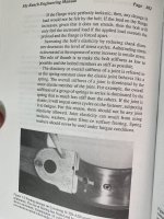
The Sky Ranch Engine Manual is an outstanding book on Lycoming engines. It blends science and physics with airplane engines. Ch7 is titled Fasteners and Failures. It has a section on p.185 called Paint and Broken Cylinder Studs. The graphic below gives explanation of Batson's post #18 about bolt stretch, preload, and fatigue.

Nev & Grant, thanks for ratcheting up the safety of our hobby. It's not easy. You guys set a high standard....Industry best standard...for us. It's safer and I'm safer due to you guys reporting this.


Screenshot 2025-02-03 at 6.17.07 AM.png Screenshot 2025-01-31 at 3.11.54 PM.png
 
On the positive side.

What we/I have learnt from this thread is valuable.

1 contamination between metal surfaces that are torqued to a specific value is a no no unless an approved product and process is applied.

2 Torques should always be to specs.

3 any oil leaks/weeps or seeps should be investigated including checking TQ of associated fasteners.

4 Any under TQ sets up a fatigue cycle that will cause failure.

5 dealing with these things by preemptively checking is way safer, cheaper, and less stressful than dealing with the consequences of a failure. Read that again.
 
On the positive side.

What we/I have learnt from this thread is valuable.

1 contamination between metal surfaces that are torqued to a specific value is a no no unless an approved product and process is applied.

2 Torques should always be to specs.

3 any oil leaks/weeps or seeps should be investigated including checking TQ of associated fasteners.

4 Any under TQ sets up a fatigue cycle that will cause failure.

5 dealing with these things by preemptively checking is way safer, cheaper, and less stressful than dealing with the consequences of a failure. Read that again.

The hold down plate clean-up procedure is completed. Data I gathered during the clean-up was.
-The plate face that marries with the cylinder had no paint on it.
-Bench inspection of nuts and plates showed that paint evidence (under magnification) under both bolt heads and outer faces of plates. So two layers of paint existed per bolt/stud joint.
-The following is not data, its feeling and unscientific logic. The feel of torque required for initial Nut removal indicated to me some preload was loss on some bolts. The shorter the stud the more clear it seemed. Not all, but not one or two. I believe all nuts were properly torqued when it was assembled. Then paint coating failed sometime after the torquing.

I built alone in my workshop for 7 years. Now I'm at an airport and have good relatioships with good people.

Ya know, I placed barriers for myself to perform this procedure, and good people came together in an interesting way to encourage hold off on beginning my test flying phase. Nev and Bissetg past experiences raised concern. I didn't test fly it due to the FAA safety inspector having issues with my airworthiness application. Then Nev Bailey's Post #54 had me investigate if paint existed on the hold down plates. A friend who is an IA looked at what I found the post #57 data point and did not agree with me that it was prudent to still do the test flying. Arborite here on this forum (LSA builder) and another GA hobbiest A&P offered there labor and collaboration to do the repair. They are giving up there time, a heated hangar and more. I tend to take a rosey viewpoint of things. "It will be okay" so I needed more data and know where to look for the data to make to tear it apart. People just lined up to help me.

Humanity and life is really quite fun when we collaborate like this. Its safer. Learning, growing, navigating risk together is pretty cool to experience. We can do more in life together. So maybe this post is here help repay a bit of the debt I owe to those who are helping me navigate the system.
 
Last edited:
Well said Brooks! My time within the EAB world over the past years has been similiarly remarkable in the same context of good people, assisting, advising, collaborating and making my experience so far a marvelous and interesting adventure.
 
That sounds like it was a good decision Brooks. I had the advantage of participating in my engine overhaul and remember my mechanic pointing out that there was and never should be any paint on those surfaces. I'm curious, what was the FAA inspector unhappy about with your application?
 
The FAA...I made a data entry in the Engine Make and Modle data that autofilled onto the airworthiness application. I said "Reciprocating - Barrows" The inspector needed them to be Lycoming and IO-360 series. I did not make up reciprocating but I like that answer. I think the EAA instructions led me to say Reciprocating. I made up Barrows because at some point in the data entry process I could not get a model type that it accepted along side Reciprocating. I seem to recall I tried several versions of Not Applicable, but it took Barrows. I looked at it and thought "they might not like that but they'll see it and tell me what they need." and moved on with the data entry. I'm not too skilled with electronic computer stuff.
 
I just watched a video from the Cleared Direct youtube channel. He has a Rans S-21, and had some prop bolt shearing problems. It looks as if his issue was from a carbon fiber mounting plate for the spinner was degrading and causing a loss of torque on the prop bolts.

While not the same as cylinder studs, it appears the root cause is very similar.

Fast forward to 14:45 if you want to see him discuss the issue: https://www.youtube.com/watch?v=r8MU-ZdFznI
 
Just adding a bit of documentation to this thread for future reference. I happened across this in an O-360 overhaul manual. The last paragraph talks about paint on the cylinder flanges for Lycoming engines that use hold down plates.

flange_paint.jpg
 
Back
Top