Tell us what you did today on your Bearhawk Project

why .. or how, did you decide to choose the shoulder ( 3 point ) over the 4 point ( centered vs lateral inertia reel ) style restraint

It was a simple decision for me - the Bearhawk airframe was already engineered for the shoulder harness. I would have preferred a 4-point harness by a small margin, but not enough to have to modify the airframe. In cars, diagonal shoulder belts are well accepted. I won’t be doing aerobatics etc. So by and large it seemed a small trade off and one that I’m willing to accept in return for a huge convenience factor. For a 4 point harness to be more effective over a single shoulder belt, an accident has to still be technically survivable and there are some accidents that just aren’t, no matter how many belts you add.

With the back seat however, it’s only engineered for lap belts. In hindsight, I do wish that I had installed inertia reels for a shoulder strap from the top center cluster. At the time I believed it would require additional engineering, but actually I now realise that my logic was wrong. The fixed lap belt is already deemed safe (enough) and adding a shoulder belt therefore makes it even more so. The strength of that cluster then, is only an issue for the serviceability of the aircraft afterwards.

Just my thought process - don’t take it as gospel :confused:
 
Incidentally, the lap-belt type latch can be fitted to the diagonal belt easily without having to be sewn it.
 
Installed a Ground Power plug, removed the Vendertherm oil screen, installed the USB charging port, installed the oil temperature sender, and tried to figure out why my ADSB isn’t working properly.

699179B3-EB1D-47FA-A01E-E73B446773BF.jpeg

B2A622AC-4CED-4715-9B43-7AA42960F93C.jpeg

F437AFED-C6F9-40CB-A27E-74FB310F95C2.jpeg

2DFA0243-76DA-4458-871F-9FAEC4BEDD30.jpeg

47B21FD9-4641-469B-88B1-2869955064B0.jpeg
 

Attachments

  • 699179B3-EB1D-47FA-A01E-E73B446773BF.jpeg
    699179B3-EB1D-47FA-A01E-E73B446773BF.jpeg
    285.1 KB · Views: 0
Awesome! How is the Vans fwf kit working for you? I might go for it later this summer minus whatever parts don’t fit our Bearhawks.
 
I would get the Vans FWF kit again, definitely. There are so many small parts that you don’t think of, or don’t know about. Huge help.
 
Admittedly not directly Bearhawk related, but I've been having a blast flying the 140, even around the pattern and always learning. I finally took up my first passenger, my son and soon-to-be autopilot, a couple weeks ago. Even with me at the controls he doesn't hate flying so I'd consider that introduction a success.
The Patrol wing framing is underway. Spars and the first few ribs are coming together. This step offers great visual gratification.
 

Attachments

  • image_9192.jpg
    image_9192.jpg
    489.4 KB · Views: 0
Last edited:
Nev,
Here in the US, when you're sitting on the ground, you may not have a tower near enough to your position for ADS-B to receive data. That would give you the ADS-B indications you're seeing. Does NZ use ground stations or satellite-based ADS-B?
 
Thanks Jim - I believe that is exactly what is happening. I think both ground and satellite here in NZ. When I searched the registration database and found my aircrafts “Hex code” and entered it into the Dynon, I was also able to see my Bearhawk on AvPlan, so my ADSB out and in are both working. We’ve now tested the radio, Emags, EMS etc, and all operational.
 
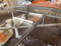
Interesting, what is the purpose of the aluminum angle? I was going to use aluminum angle different - I was going to pop rivet some angle to the outside to hold nut plates on the underside of the 1/2 inch steel tube. I couldn't figure out how to rivet the nut plates in place any other way other than maybe bonding.

I am about to attach my skylight as well.
 
The aluminium angle is capturing the sides of the Lexan. I’ve put rivnuts in the steel former underneath. Theyre supporting a shear load, so should be plenty strong enough. I’m also using rivnuts on the two center stringers. Actually where the bulk of the lifting force is, there’s probably no need for the screws at that point because the way the Lexan curves over the stringers seems to lock it firmly in place, although I’ve got them anyway. But further aft the skylight is prone to lifting. So I’ve got two rows of M4 machine screws on those stringers and the outside edges of the skylight are captured all the way around.

The only point I’m still pondering is if I should wrap the front and rear edges in felt (or something - what ??). It does need something to pack it out and I’d rather not silicon it in permanently.

Any ideas welcomed.
 
How are you going to attach the wing root fairing to the piece of angle that is capturing the sides of the skylight?
 
I am getting ready to swage my control cables, made up some inserts to have it all run smoothly and so nothing will bind up. I also cut out the material for the firewall heatshield. Ready to go to the upholsterer. Waiting for the tin plated sleeves and bolts and nuts and more control cable to arrive from the states. It amazed me to see how many people in aviation do not know that the zinc plated sleeve will not work on SS control cable, only the tin plated ones, the zinc plated sleeves will cause galvanic corrosion. When I received my hardware kit from Aircraft Spruce ten odd years ago, they send me the SS cable, but with zinc plated sleeves. Its always best to do proper homework on what goes with what.
 

Attachments

  • photo9259.jpg
    photo9259.jpg
    908.8 KB · Views: 0
  • photo9260.jpg
    photo9260.jpg
    1.1 MB · Views: 0
  • photo9261.jpg
    photo9261.jpg
    1.2 MB · Views: 0
  • photo9262.jpg
    photo9262.jpg
    1.3 MB · Views: 0
  • photo9263.jpg
    photo9263.jpg
    1.4 MB · Views: 0
  • photo9264.jpg
    photo9264.jpg
    1.5 MB · Views: 0
  • photo9265.jpg
    photo9265.jpg
    898.1 KB · Views: 0
  • photo9266.jpg
    photo9266.jpg
    1.3 MB · Views: 0
It has been about a month - have you installed either pitch or roll servos. Really interested in your success as I will put the same system into my Patrol - whenever I get my kit! Don
 
Hi to all, this is a question specifically to those who has fitted their wings, do I drill the airframe holes for the main spar to fit the AN6 bolt and rear spar to fit the AN6 bolt both holes before I fit the wings, I understand the procedure to set the wing angle of incidence correctly and the wing to fit square to each other and in relation to the airframe that has been levelled with the tube and water method. If any of you can share what you did and what you would improve if you have to do it again. I made up the drill guides for AN5 and AN6 bolts.
 

Attachments

  • photo9292.jpg
    photo9292.jpg
    1.2 MB · Views: 0
  • photo9293.jpg
    photo9293.jpg
    1.3 MB · Views: 0
  • photo9294.jpg
    photo9294.jpg
    1.4 MB · Views: 0
Thanks Rob, I did follow that discussion. I plan to move to the coast and personally think the SS control cable will last longer in coastal areas. I will keep my eye on them for sure.
 
Hi to all, this is a question specifically to those who has fitted their wings, do I drill the airframe holes for the main spar to fit the AN6 bolt and rear spar to fit the AN6 bolt both holes before I fit the wings, I understand the procedure to set the wing angle of incidence correctly and the wing to fit square to each other and in relation to the airframe that has been levelled with the tube and water method. If any of you can share what you did and what you would improve if you have to do it again. I made up the drill guides for AN5 and AN6 bolts.

Bob's wing drilling document says no. You start with undersize holes in your wings and fuselage. Then you loosely pin the wings to the fuselage with AN3 bolts Then you align everything, then match drill with your drilling jig.

Bob Barrows document titled "Drilling Your Wings to your Fuselage" available on Bearhawk.tips. (I'm not sure I have authority to attach to my post.)

I followed the document pretty much to a tee and would do it again that way.... so I left my wing/fuselage attach holes undersized while the wing alignment procedures were accomplished. Then I drilled the holes to final size. I used a drilling jig like you have, but moved up from the undersize holes to the final size holes incrementally by placing tube sleeves in the jig that would accommodate the undersize drill bit and keep the undersize drill centered.

The water level... I had about 5 versions of it until I settled on a a very satisfactory design. 3/8" tube is good. 1/4" tube is not good...too bouncy and more difficult to read. A bucket was attached to the wall and was my water level reservoir with a height about 10-12 inches below the bottom of the wing. I took a 24" stick and attached a metric ruler to it then attached the user end of the water level tube on top of this assembly so I could see through the water in the tube to the ruler. But then when I raised the stick up to touch the bottom of the wing I could not read the level of the water on my small ruler so I got out my magnifier reading glasses. I then I could read it so good that I got unreliable results because I could not reliably hold the tube square and in place until I attached my orange plastic post level to the ruler/tube assembly. After those changes, keeping the tube straight up-down and reading it with my magnifiers, I was able to measure anywhere the tube could reach within 0.5 mm accuracy. I could move from the left wing to the right wing and get each position set just right with very high confidence. I could move out to the wing tips, it was wonderful.
 
Went backwards this week, doing final prep for 1st flight the Dynon went black. Will ship back and pay standard $450 repair fee. Probably 4 week delay. Damn

Did the entire screen go blank, or when you press the display button does it go blank above the bottom menu ? Do you have the “Swap Screens” virtual button enabled ?

I had an issue with mine when I pressed the display button. Dynon we’re less than forthcoming with the issue, however it is a known issue among their customers that has been around for a while. It’s related to the “Swap Screens” function. They have released a file to fix the problem (but it doesn’t fix it permanently). I was told off by off record that Dynon recommends not using the swap screen function, which is very odd since they included it as an option. In the meantime I have disabled the Swap Screen button.
 
Last edited:
No, just completely black. Spent an hour with the Dynon tech. Unfortunately it is more than 3 yrs old, so no warranty. Hopefully they will return it quickly.
 
No, just completely black. Spent an hour with the Dynon tech. Unfortunately it is more than 3 yrs old, so no warranty. Hopefully they will return it quickly.

Sorry to hear that, definitely a pain in the wallet. Already I’ve had to send back my exhausts pipes, and very recently the Emags. In both cases the manufacturers turned the products around quickly and covered the freight costs one way. In the case of Emags, they shipped a replacement set to me before I had sent mine to them. So no complaints about the service and if (or when) I build again I would have no hesitation in using these companies.
 
I had the same happen to me just before first flight. Fortunately I was still under warranty with Dynon. They crossed shipped me a new one in 2 days. Sorry...
 
Last 2 days I drilled the windshield fairing to the boot cowl and installed nut plates, fabbed the backing angles, drilled and installed nut plates. Installed nut plates on the windscreen pillar. I made up covers for the windscreen pillar/fuel lines/wiring. I think I set a new personal record for most attempts at making parts. I think it took me 9 or 10 attempts to make the 2 outside covers.
 
I made the centre floor board where the elevator cable goes through the floor and underneath the flap lever.
 

Attachments

  • photo9359.jpg
    photo9359.jpg
    1.5 MB · Views: 0
  • photo9360.jpg
    photo9360.jpg
    1.8 MB · Views: 0
  • photo9362.jpg
    photo9362.jpg
    1.9 MB · Views: 0
  • photo9361.jpg
    photo9361.jpg
    1.7 MB · Views: 0
  • photo9363.jpg
    photo9363.jpg
    1.9 MB · Views: 0
Looks very nice! What did you fill the gap in your windshield/skylight double-channel with? Looks like it painted well and must be rated for UV resistance?
 
Looks very nice! What did you fill the gap in your windshield/skylight double-channel with?

Thanks. I used adhesive backed felt, designed for pool tables. I found it at the local fabric store and worked perfectly.
I don’t think there’s anything special about the UV resistance (unfortunately) and I tried to source some polycarbonate with Noxtat treatment for chemical resistance too, but was going to be prohibitive cost-wise here in NZ. I’ll use a couple of the removable sun screens that Rob Caldwell posted a few weeks ago.
 
Looks great. I painted some small bits on my sky light install, it should be going on permanently in the next day or so.
 
I have seen the paper clips used to determine how high to cut baffling on the engine top so you know how much space to the upper cowling. Mark
 
for me, the decision to build was huge. I recall thinking "A decision to build or not to build has to be made. What will people think when I tell them?"
 
After almost 3 years of hoarding parts I am finally building! Laid out the upper frame on the jig table tonight. It doesn’t look like much, but I’m excited. I was chomping at the bit to get started, but had to finish a truck restoration with my son first and I didn’t want multiple big projects going on at the same time. I am using the VR3 kit and it’s a dream. I’ve built a fuselage years ago from raw stock and I would never do it again. Pre notched kits from Mark or VR3 are worth every penny in time savings, frustration and wasted tube. A pre welded kit would be even better, but I’ve always liked to weld my own stuff so here we go!
 

Attachments

  • photo9692.jpg
    photo9692.jpg
    2.6 MB · Views: 0
  • photo9693.jpg
    photo9693.jpg
    2.4 MB · Views: 0
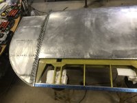
Neat! That is sheet metal on the H stab right? Whats the black on the leading edge there? Are you going to cover much of the plane in metal? May I ask why? You have some really interesting ideas - I like seeing your updates. Cheers!
 
I work out of state every other week so I’m hauling some of the smaller parts with me to work on in the evenings. Boss let’s me have access to the machine and welding shop so I built a jig and started welding up rudder pedals and control sticks tonight.
 

Attachments

  • photo9727.jpg
    photo9727.jpg
    2.5 MB · Views: 0
I worked at a remote job site before retirement (Gas processing plant, Prudhoe Bay Alaska). I was able to do the same thing with the great welding and machine shops we had. I always was taking materials north and bringing parts home. Even built stabs, elevators, and rudder there.
 
Rodsmith that’s awesome! I plan on doing about the same parts there. Id rather stay late and do this than go back to the hotel and stare at the walls.
 
That's a lot of extra work but will look nice, especially with your metal tips. I was lazy and just overlapped my Hoerner tips over the wing skin.
 
It is a lot of extra work but worth it. I did it and I'm going to do the same with the engine cowling
 
I did the same. Bob suggested that the flange be at least 3/4" ( mine is 1") and space the nut plates 3" apart. He said to use .032 AL.
 
Last edited:
Decided to take a break from composite work. I had built my cowling sometime ago but had never installed a door over the dip stick. I was unsure at the time how I was going to joggle the skin for a flush door. I have a harbor freight beading tool with a joggle die, but it is designed to joggle an outside edge, not an inside cut out. Sometimes you have to think outside the box and modify the tools you have to get the desired result. I had bought a hidden oil door hinge from Avery when they were going out of business. I am really happy with the clean look. This little project took much longer than it should have but that seems to be the norm.

DSCF1283.JPGDSCF1285.JPGDSCF1287.JPGDSCF1288.JPGDSCF1294.JPGDSCF1296.JPG
 
I added .025" 4130 plates to the leading edge of my elevators today, tomorrow I will pour the lead weights. The process was to first tack the plates in place being very careful to keep the plates below the level of the outside tubes so that when fabric is added it won't touch the plates. Then I brazed around the edges to seal them against the tubes, I ground the brazes flush. Finally I added three steel dowels between the plates to act as an anchor for the lead.

pic4-s.jpgpic5-s.jpgpic6-s.jpg
 
  • Like
Reactions: Nev
This is an extremely useful tool among sheet metal fabricators. Two thumbs up !
I purchased an 18" model with various sets of dies for rolling options.
 
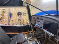
I was planning to get some vinyl for the top of the instrument panel the same as the seats. However here in NZ we're in lockdown while our prime minister personally eradicates the Delta variant of COVID 19. Everything is shut.

So I ended up reverting to Kydex (I know, I know). And I had a piece of rubber trim that I bought a while back as a sample which fits very well too. I’ll add Velcro underneath so it can all be easily removed to access the avionics rack. Really happy with the results.

0D22BD63-8AEE-421B-B70B-44C7756451E9.jpeg

8DB2E7B8-5DE0-4D6A-A402-7A40A1E4911D.jpeg
 
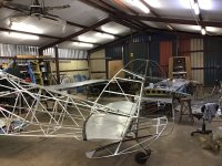
A little more framed up. Missing some tubes from VR3, but as soon as I get those in I’ll buckle down for a couple days and weld it out. Sorry for the poor lighting. It’s still pretty warm here so working at night is the way to go right now. Plus it’s nice and peaceful with no interruptions.
 

Attachments

  • photo9905.jpg
    photo9905.jpg
    2.7 MB · Views: 0
  • photo9906.jpg
    photo9906.jpg
    2.4 MB · Views: 0
So far I have been very pleased with the pre coped tubing kit. It’s almost self jigging in some ways. I have 3 plumb bobs down the middle and the worst one Is out the width of the pencil line on the table.
 
I finished the fuselage this morning, more or less. So I rented a trailer and brought the wings up. I’ve decided to leave one wing crated, then I put the flap and aileron back inside the top crate until I’m ready to work on them. Hats off to the scratch builders out there !

E058F26D-3808-4DBE-B96D-4A691641BC30.jpeg

E28AF10F-A35C-40E3-8684-5D3920035CC1.jpeg

C474B247-C366-4275-BE74-89B2B4538CFE.jpeg

DD20B071-F85D-4104-9B85-354E8C9985F4.jpeg
 
Nev, are your tanks installed? Wings set to the fuselage from the factory?

I think my tanks are set, but not the wing to fuselage.
 
Nev, are your tanks installed? Wings set to the fuselage from the factory?

I think my tanks are set, but not the wing to fuselage.

Yes my wings are set, so are the wing struts. Bolt holes all ready to go.

The tanks are only temporary installed and need to be removed and unwrapped (which I did this evening). I’m thinking of using an adhesive backed foam on the tank straps, if anyone has done this before feel free to comment. I seem to recall reading that some are using strips of carpet.
 
Last edited:
Back
Top