Bearhawk Aircraft Bearhawk Tailwheels LLC Eric Newton's Builder Manuals Bearhawk Plans Bearhawk Store

Announcement

Collapse
No announcement yet.

Franks LSA

Collapse
X
 
  • Filter
  • Time
  • Show
Clear All
new posts

  • #16
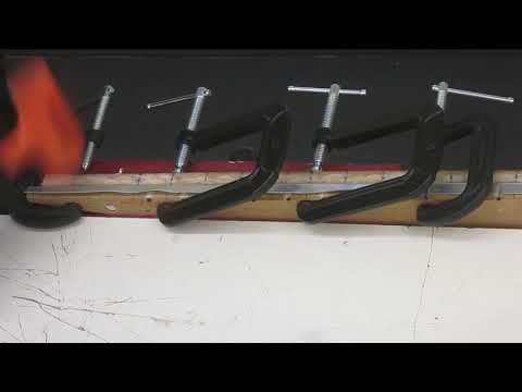
    Finally I have a system rigged up to produce rib flanges.

    The two form blocks (which are copies of the working template) were run through the router using a flush cutting bit, an angled fence, and and inclined table. This resulted in a 10 degree bevel, one for “left” flanges and one for “right” flanges.

    Using a 1/16 radius roundover bit in a small trim router, went around the working edges of the form blocks, even though the LSA book specifies 1/32.

    Studied and thought a bit, then marked rivet locations. Then indicated the flute locations, which are slight grooves and serve as initial guides.

    Gave the working edges and surfaces a couple of coats of a wood hardener. Hopefully this will help the form blocks and backup block hold up to the abuse.

    Made a practice set up (form block and backup block) which replicates the tightest curve on the nose rib and worked on bending technique.

    Making homemade fluting pliers was more a rite of passage than anything else. They are so-so, and I see how I could do better a second time. But it’s pretty hard on the drill press. Fluting pliers I bought from Airports Inc. work much better.

    B-Spot on youtube inspired me to make a table mounted fluting vise along with the Vans-style rib straightener. The fluting vise gives a nice moderate 3/16 flute. And the Vans rib straightener really works, though I may need to refine the angle. It also serves as a flute reducer.

    The only difficult areas are at the first three or four flutes over the front of the nose rib. These seem to require a bit of the store-bought fluting pliers to get a little deeper. And smooth-jawed pliers to go in and fine tune the flange. The trailing edge of the back rib is too tight for the rib straightener but it’s workable with the pliers.

    So that’s the plan going forward: bend the flange over in the form block and start the flutes using a 3/16 rod and hammer. I can do a nose rib and center rib at the same time. The back rib is done separately. The pieces come out of the jig with close to a 90 degree flange. The flange is refined with the fluting vise, rib straightener and pliers.

    The goal is to create rib flanges where the inter-flute surfaces match the line of the airfoil, as opposed to bowed surfaces between the flutes. Maximize contact between the flange and the skin, and not rely on the skin and rivets to pull the flange into shape.

    We’ll see how it goes!
    You do not have permission to view this gallery.
    This gallery has 20 photos.
    Last edited by Frank; 01-16-2021, 06:28 PM.
    Frank Forney
    Englewood CO
    https://eaabuilderslog.org?s=FranksLSA
    EAA Chapter 301

    Comment


    • NCLSA183
      NCLSA183 commented
      Editing a comment
      I like the way your ribs are looking. I also used an angled form block and the triangle shaped flange recesses on my RV-6 project in the 90's. Used a tapered shaft Craftsman punch for setting the flutes into the recesses. I prefer the triangle shape because of the way the material needs to stretch and it seems to make it easier to get the flat parts flat. At least for me. I sold most of my aircraft specific tools years ago but I still have my Craftsman punch.

  • #17
    fullsizeoutput_102d.jpegfullsizeoutput_102c.jpeg
    About a quarter of the way making basic rib flanges. With a ten degree bevel they come off the form block with close to a ninety degree flange.

    Seems to be working out okay, though the backup block is taking a beating. I'll have to duplicate it soon. And when the time is right, I'll use the two backup blocks as the hole flanging jigs. Testing the arbor press and die seems pretty straightforward. Got the bob-stick ready.

    Thinking about a little contact cement inside the die jig sandwich to minimize the aluminum sliding/stretching (along with as much clampage as I can get).
     
    Last edited by Frank; 01-29-2021, 06:07 PM.
    Frank Forney
    Englewood CO
    https://eaabuilderslog.org?s=FranksLSA
    EAA Chapter 301

    Comment


    • #18
      As I study and work to understand, it helps me to separate out parts which in the plans are drawn overlapped. I had the plans scanned into pdf files, so it's now easy to go in and make tracings. Not for accuracy or dimensions, just to see more or less what's what.

      This, like my materials and parts lists, is a work in progress. wing spars 01.png
      Frank Forney
      Englewood CO
      https://eaabuilderslog.org?s=FranksLSA
      EAA Chapter 301

      Comment


      • #19
        This is great John thanks for doing it and posting.

        Comment


        • #20
          Completed all basic rib flanges except for the two .032 center root ribs. They came off the 10 degree beveled form blocks with a nearly 90 degree flange. Did a "basic" job of straightening and flattening. Adding lightening holes with flanges will add new distortions, so at this point I didn't strive for perfection.

          The form blocks and back up blocks are showing signs of wear, though still useable. I doused each with Minwax wood hardener a couple of times through the process. Not entirely sure it does any good.

          One small alteration to the method was added, and that was to flute the top of the nose rib blank before bending. It is just that area where the curvature of the airfoil is greatest which tended to produce annoying wrinkles. But starting the flutes before bending made this go smoother. This was suggested to me by a Zenith builder.

          The short video shows trying to get the most out of the table-top fluter and rib straightener, applying pressure at different points, really digging it in.

          The aileron and pocket ribs were bent over straight (non-beveled) form blocks. Easy enough to straighten the flanges with smooth jawed pliers. I was struggling with the top/bottom dimension of the pocket ribs, but decided to leave the bottom tab flat. Will bend that upon assembly to get the best fit.

          All the pieces will need to be trimmed to length upon assembly. All the cutting templates and form blocks are intact and still usable if necessary.

          But for now, it's on to the lightening holes!

          video, sharing, camera phone, video phone, free, upload
          You do not have permission to view this gallery.
          This gallery has 6 photos.
          Frank Forney
          Englewood CO
          https://eaabuilderslog.org?s=FranksLSA
          EAA Chapter 301

          Comment


          • #21
            Those debating which method to use for cutting and forming the lightening holes may find this useful. Might make you more convinced than ever that the router method is the way to go. But I'm glad to be using the fly-cutter and drill press. Next step will of course be to form the lightening hole flanges using the dies and arbor press.

            Using the two backup boards from the rib flanging step, the oversize holes were cut, creating a rib-sandwich jig. First, they serve to hold the ribs in place for cutting. Secondly, the holes are the bending edges over which the dies forms the flanges.

            Cutting from both sides of the material gives me the cleanest edges. This applies to both MDF and aluminum. Cutting all the way through from one direction is problematic. So for the most part, I start the cut from one side, flip the piece over, then finish the cut from the other side. Alignment is not a problem with the guide hole.

            Since I am leaving the plastic film on the aluminum as long as possible, this also causes problems trying to cut through from one side. The plastic can interfere with the cut and also trap chips underneath around the hole.

            Fortunately, the smaller holes presented much fewer problems and I was able to cut through cleanly from one side.

            The cutter will grab and bind, both in the MDF and the aluminum. But when the cutter stops, the motor just slips on the pulley. In other words, the full torque of the motor is not applied to the work when the cutter binds. You just back off and the cutter resumes spinning. And an extreme amount of clamping is not required.

            The drill press and hole cutter method is not loud and the dust and shavings are easily contained by the safety shield. Other measures include not wearing gloves, and plugging in to a switched outlet.

            The video shows it in detail:
            https://www.youtube.com/watch?v=bVcHegOH8yE
            You do not have permission to view this gallery.
            This gallery has 12 photos.
            Last edited by Frank; 04-04-2021, 06:18 PM.
            Frank Forney
            Englewood CO
            https://eaabuilderslog.org?s=FranksLSA
            EAA Chapter 301

            Comment


            • #22
              Looks like your making lots of progress Frank Thats a nice set up you have too.

              Comment


              • #23
                Naturally, now that I'm almost done flanging the lightening holes, I start to second-guess myself. For the outer flanges of the ribs, I radiuses the edges to 1/16 inch. (The Bearhawk LSA Book says to radius these edges to 1/32.)

                But I didn't radius the edges of the lightening hole forms. My test seemed to indicate it was not necessary. And indeed all of the lightening hole flanges have a visible bend radius even though bent over a sharp edge.

                Now I bent a piece of .020 over a sharp edge to 90 degrees and it has a radius of about 1/32 as near as I can measure. Visually it is about half the bend radius of my 90 degree rib flanges.

                Table 4-6 in AC 43.13-1B gives recommended bend radii for 90 degree bends. For .020 that is just a little less than 1/32 (and see the table footnote). It doesn't mention 30 degree bends.

                I'm not trying to achieve the minimum radius. But I think I am ok with the bend radius of my lightening hole flanges.
                You do not have permission to view this gallery.
                This gallery has 7 photos.
                Last edited by Frank; 04-13-2021, 02:04 PM.
                Frank Forney
                Englewood CO
                https://eaabuilderslog.org?s=FranksLSA
                EAA Chapter 301

                Comment


                • #24
                  The ribs were sandwiched between the two backup blocks/lightening hole jigs and the flanges were pressed using the MDF dies and the arbor press. It was important to press lightly at first and rotate the die in order to get an even angle on the flange. Also important to not continue to press or press too hard because cracks may develop.

                  There were some rejected pieces because of cracks, and even though I made extras to begin with, I am still short one back rib and one aileron rib. I won't remake these pieces yet because I may discover more rejects as I move forward. The plastic protective film is still on the aluminum, not to be removed until it's time to de-burr.

                  The ribs had been fluted and straightened but the lightening hole flange pressing created a new distortion in the ribs. This was removed using the bob-stick by stretching and lifting the flanges in the proper locations. I used a sweeping motion while pulling on the bob-stick in order to keep the flanges smooth.

                  Also some adjustments to the ninety degree outer flanges and flutes were made. Overall, the ribs are now in pretty good shape with regard to flatness and straightness. I suspect I will be tweaking them again before and after adding the stiffener angles and upon assembly.

                  The youtube video shows the entire process.

                  https://www.youtube.com/watch?v=rLwtF_EmOeY
                  You do not have permission to view this gallery.
                  This gallery has 16 photos.
                  Frank Forney
                  Englewood CO
                  https://eaabuilderslog.org?s=FranksLSA
                  EAA Chapter 301

                  Comment


                  • #25
                    This is my pile of rejects so far. Either there are cracks or the flanges are too eccentric or I have mangled the piece beyond repair.
                    You do not have permission to view this gallery.
                    This gallery has 1 photos.
                    Frank Forney
                    Englewood CO
                    https://eaabuilderslog.org?s=FranksLSA
                    EAA Chapter 301

                    Comment


                    • #26
                      Looking good Frank!!!

                      Comment


                      • #27

                        My biggest goof so far: gap between nose rib lightening hole flanges is 3/8 instead of 1/2.
                        I sent Bob a picture with my proposed solution and he replied “3/8 as you show will work good”.
                        The centers of the holes are correct so the mistake occurred when scaling up from the drawing.
                        ​​​​​​​Will adjust rivet locations for better spacing.
                        It's a warning and foreshadowing: must look forward to see the consequences of all measurements.
                        I fear my lack of comprehensive understanding of the plans will bite me harder next time!
                        You do not have permission to view this gallery.
                        This gallery has 1 photos.
                        Last edited by Frank; 05-16-2021, 01:09 PM.
                        Frank Forney
                        Englewood CO
                        https://eaabuilderslog.org?s=FranksLSA
                        EAA Chapter 301

                        Comment


                        • #28
                          Obviously there are other ways to go about it but these are the steps I took to make the rib stiffeners:

                          1. Cut the 1 inch blanks on the table saw using a sled and stacked rough cut pieces of aluminum.

                          2. Trim the blanks on paper cutter. There are five separate lengths and as many as 36 each.

                          3. Make five drill guides from 1/2 inch aluminum bar stock from hardware store. Cut the bar with jig saw and refine the ends with disk sander. Make a jig to hold the piece and drill the holes. Add nails as jig pins and insurance. Add a slight chamfer to each hole to aid the drill guide.

                          4. Stack six or eight blanks with the drill guide in the jig and clamp together. The jig rides freely on the drill press table and the drill guide does the work of alignment. Add the nails again as jig pins as insurance.

                          5. Use the disk sander to cut the angles into the stack of blanks.

                          6. Use a simple bender to form the angles. Made from MDF and 1/8 masonite. A 10 degree angle is cut into the fence/shoe/ clamp. The 1/8 material brings the bend to the center of rotation. A piece of aluminum under the shoe serves as a 1/2 inch stop. Three nuts and washers are torqued down to clamp it together.

                          7. Using the drill guide and cleco-clamps, measuring from the spar-ends of the ribs, drill the holes in the ribs. “Left” and “right” ribs use the same drill guide, just rotated 180 degrees.

                          8. Randomly cleco ribs and stiffeners together to check the fit.

                          Photos not in sequence.

                          See the Youtube video for steps in detail:
                          https://youtu.be/QVNxnR8ypY8
                          You do not have permission to view this gallery.
                          This gallery has 19 photos.
                          Frank Forney
                          Englewood CO
                          https://eaabuilderslog.org?s=FranksLSA
                          EAA Chapter 301

                          Comment


                          • #29
                            Hey Frank i really liked your idea of the drill guides for making the rib stiffener angles. I have not started on my wings yet but i am gathering all the materials for them. I wanted to ask what model blade are you using in your table saw to cut the aluminum bar?
                            Last edited by davzLSA; 07-11-2021, 05:19 PM.

                            Comment


                            • Frank
                              Frank commented
                              Editing a comment
                              I think the 10 inch circular saw is a Diablo non-ferrous metal blade (used to cut stacks of .020 and .025 into 1 inch strips). And the 1/2 inch aluminum bar was cut using a table mounted jig saw with a metal cutting blade. (You will be better off using a band saw: the reciprocating jig saw isn't that great). I'm just trying to use the tools I have, and that sort of dictated the method. ​​​​​​​​​​​​​​

                          • #30
                            would the circular saw cut the bar?

                            Comment


                            • Frank
                              Frank commented
                              Editing a comment
                              Probably if it's solidly clamped. But my fall-back was going to be a hacksaw for the 1/2 inch bar. After all, it's just a few pieces. I plan to use the table saw sled again when time to trim the rib lengths for assembly. Cuts through thin metal without any drama.
                          Working...
                          X