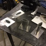
Tell us what you did today on your Bearhawk Project

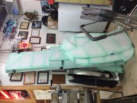
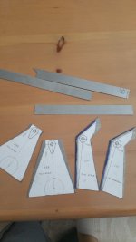
Created spar attach plates and splice plate master routing patterns.

833faedde147f977ea2f37ac80068ce7.jpg


Sent from my iPhone using Tapatalk
 
Not exactly Bearhawk progress, but closely related:
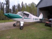
This week, everything finally came together to get started on my tailwheel training in my "new-to-me" '65 Citabria 7ECA with O-200 engine. Two hours on Tuesday, and another hour today, and I'm starting to get the hang of 3-point landings. We even had a 5-knot crosswind today, so it was a perfect "next step" from the dead calm air we had for the first flight. Having tons of fun!
 
No Title

A milestone, of sorts... I've covered everything, short of the fuselage. So, it's time to tackle the fuselage! All the little bits have been an adventure and I've honed the rusty technique, to the point that I'm comfortable taking on the biggy. BUT, before covering the fuse, a rotisserie is a must, so create a rotisserie I will!

And yes, Jim. Tailwheel familiarity does count as progress on the Patrol! In my book, anything that gets you closer to flying your plane, is progress!

Bill
 

Attachments

  • photo2583.jpeg
    photo2583.jpeg
    667 KB · Views: 0
Yeah, my hangar mate has a CH-750, and flies up to a grass strip near here all the time. One of the guys up there has a Stearman, and about 2 weeks ago, my buddy got a flight in it. Said it was a "big round airplane, with a big round engine, that flies big round maneuvers very gracefully." I thought that was a pretty cool description.
 
I know exactly what you mean! I've come across more than a few tasks, that I've avoided, either due to apprehension about my skills, or just plain not wanting to screw something up. So far (fingers crossed) each task has proven to be no big deal. I suspect much of this, is because I think it to death! But, that's how I work...
The strut looks mighty fine, Whee!

Bill
 
Thanks Bill! I agree that the extra thought that goes into the parts I avoid help make it go better. But sometimes you just have to dig in a get it done.
 
No Title

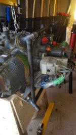
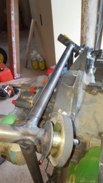
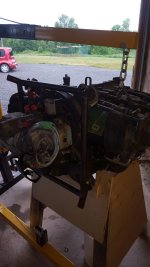
Finally got the gumption (and courage) to start tackling the engine mount. I built a heavy duty stand to hold the O-540 at a reasonable height to work on it, and just got started. So far, I have made the mount ring and will be starting the actual ring-to-fuselage the tonight. As Bill and Whee said, there are areas/steps that get put off due to any number of things, but in my case, it is mostly from fear of the unknown (i.e. I'm not sure how to do something or figure it is really hard and I will screw it up). Although the ring mount is pretty simple, I got an inordinate amount of satisfaction of completing it. I'm really looking forward to getting at the next part of the mount!
 

Attachments

  • photo2590.jpg
    photo2590.jpg
    165.8 KB · Views: 0
  • photo2591.jpg
    photo2591.jpg
    147.1 KB · Views: 0
  • photo2592.jpg
    photo2592.jpg
    144.4 KB · Views: 0
I'm still going to need a lot of courage to tackle an engine mount! It's kind of an important piece of the puzzle! My initial engine choice for my project is an M-14P, so it's even scarier in my mind...
 
Well, Chris, I may have some good news for you! In a previous life, I was building a Murphy Moose, that was to be powered with a M-14P. I had the engine and prop. If you get a new engine, as I did, the engine comes mounted, in the crate, with a mount ring attached. You still need to build the support structure that bridges to the firewall, but you don't have to figure out all the geometry that actually attaches to the engine... Or, you could get in touch with Jim Kimball, in Florida. Those guys are the Guru's of M-14's, IMHO.

Bill
 
I'm rebuilding the lower cowl section, mostly because it didn't turn out great the first time. Now is a handy time since I'm also changing the exhaust system. In the wee hours tonight I worked on the fiberglass portion that covers the FAB, and hopefully it will turn out better this time with me having a bit more fiberglass experience. The plane has been out of service for a month through this process, and when the second edition of the exhaust arrives tomorrow, I'll find out if it fits. If it doesn't, I'll start to get worried about having it together in time for Oshkosh. This was not a good time of year to undertake this process.
 
No Title

Here is a deviation from the plans that anyone who has spent any time upside down under an instrument panel should appreciate. Tomorrow the sheet metal gets prepped, primed and painted. I don't know why it rotated toe one photo.
 

Attachments

  • photo2601.jpg
    photo2601.jpg
    1.2 MB · Views: 0
  • photo2602.jpg
    photo2602.jpg
    1.3 MB · Views: 0
No Title

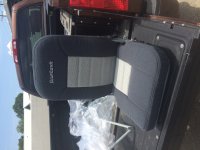
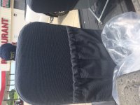
Not really progress on my Patrol, but progress on Ron B.'s Bearhawk. We picked up the seats for Ron's project! Man, they look nice! The pictures don't do them justice;

Bill
 

Attachments

  • photo2603.jpeg
    photo2603.jpeg
    911.6 KB · Views: 0
  • photo2604.jpeg
    photo2604.jpeg
    726 KB · Views: 0
  • photo2605.jpeg
    photo2605.jpeg
    891.3 KB · Views: 0
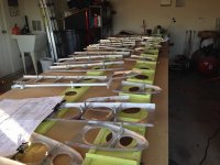
Put together a couple of temporary work tables in the garage so I can cut the 4x12x.125" into capstrips and spar plates. Not enough room in the basement, so off to the garage with me! A little bracing to go, and then ready for business.

3499c364cc8e59dd7454df836f486e5d.jpg


Sent from my iPhone using Tapatalk
 
No Title

Whew! Pushed pretty hard this week (and enjoyed every minute!). Finished the initial taughtening of my fuselage. Still have two more ironings and LOTS of tapes. But 'phase one' of covering the fuselage is done!

Really enjoying this!

Bill
 

Attachments

  • photo2612.jpeg
    photo2612.jpeg
    413.1 KB · Views: 0
  • photo2611.jpeg
    photo2611.jpeg
    469.3 KB · Views: 0
  • photo2613.jpeg
    photo2613.jpeg
    640.1 KB · Views: 0
No Title

Bearhawk 727 finally got its wings finalized on Thursday.

We hit a self inflicted snag. The wing skins were extended 1/2" at both ends for nut plates. The problem was that the skin extension did not leave any finger room between the wing and fuselage. Wings back into the shop. Inboard skins trimmed back to ribs & nut plates reinstalled. Much better & the way it was intended.

The fuselage was leveled side to side with the water level. The gear was solid blocked and hard shimmed to get the fuselage level. if we needed to slide a shim under the tire was aired up & then the air let out so the weight was on the blocks. It stayed dead level through the process. The right wing was raised with the drywall lift & preliminary level set. Then the scaffold was erected around the end of the wing with out the x brace on the inboard side. We used a 3" ratchet strap & a piece of styrofoam board to hold the position. The left wing was set in position with the drywall hoist as we wanted to do both wings at once. We used a 4 ft level with a spacer block to set the preliminary angle. To get the block height at the 46" edge is simply 46 x 2 x Pi divided by 360. A couple tries on the table saw to get the right thickness for the digital caliper. The left wing needed a minor adjustment to get the water level reading while the right wing was on the money.

The drilling of the attach holes made us think a bit and went easier than expected. We were fanatical in building the fuselage that carried into the measuring & setting the fuselage attach points exactly where they were needed. When we were assembling the fuselage we used a lot of string lines and plumb bobs to get top and bottom fuselage frames running on top of one another. We put light punch marks on the tubes that go across between the attach points as centerline references for measuring the attach points so the centerline was not lost. The fuselage was dead straight post welding thanks to our welder partner so getting the wing attach alignments worked out. We ran a rod through the fuselage attach points to mimic the Bearhawk and Newton's method of aligning the wing attach holes.The spacing on the front set was size for size and the rear set had an extra 1/16" added to give wiggle room. We loctite glued the shim washers in before clamping and drilling. The wing was built level & square with the attach holes offset 3/8" similar to Russ Erbs method so the bores did not align. The fuselage was drilled at 1/4" and the wings at 3/16" so a little head scratching on getting the different sized holes aligned. Some of the best things happen by accident. We used 1/4" x 3/16" id tubing to make bushings for the backside attach holes. We wiggled the 3/16 bolt until it centered on the side where the drill was to start and then clamped the assembly tight. We measured from the same outboard points on the wing to the same place on the tail post to have about an 1/8' difference.
The first pass was with a 1/4" bit that pushed the 3/16" bolt out and stayed centered as it backed the bushing out. This set the aluminum wing hole at the same angle as the fuselage attach. The attach holes were drilled out in steps and then reamed. The bolt hole center to center distance measured exactly the same on both sides.

It feels good to have this done and behind us.
 

Attachments

  • photo2617.jpg
    photo2617.jpg
    83.8 KB · Views: 0
  • photo2618.jpg
    photo2618.jpg
    375.8 KB · Views: 0
  • photo2619.jpg
    photo2619.jpg
    383.3 KB · Views: 0
Last edited:
It was the way it worked out for us. The top of the cabin follows the wing profile and flows into the fuselage. We were frustrated with the huge tail spring & tail wheel so we decided to give the stinger a try. We started out with the Scott's Iron Design tailwheel that we bought before the Bearhawk wheel came along. We did not care for the big tailspring arrangement. We talked with Scott's and exchanged the tailwheel for the stinger arrangement. He made the assembly for us with the mounting plate shipped loose so we could set the mount angles to get the correct caster.

Time will tell how the stinger will work out. The engine is a Continental IO-360 210 hp that eliminated the air inlet on the lower cowl. My partner wanted to have the sloped cowl similar to a Sherpa as he thought it was STOL friendly. The nose bowl is the typical MC3A but I had to build a new bottom half to be flatter to stretch over the bed mount so he got the sloped under cowl.
 
Last edited:
Hi All!,

First post for me and I'm glad to say I completed step 1 for Patrol 315 this weekend. Well, I guess step 1 and then step 0. Saturday I cut out the mylar, glued it to a piece of 3/4" Finnish birch plywood and cut it out and sanded. It's pretty close to the mylar with a couple of places under the line. I doubt it matters. I also laid out hole and spar locations.

After spending a few hours hunched over my work (I'm 6'5") I decided I would spend Sunday building some new benches. I finished one and a half EAA 1000 benches today. They're per the manual except I used melamine for the top and I raised the finished height to 42 inches. Nothing too exciting, but I had a blast.

Kevin
 
Kevin,
Welcome! Tables & pattern are the first steps in a big adventure. Make them comfortable as you will spend a lot of time on them. It is good to have a comfortable stool & chair handy. Good lighting for the fine work. A radio made it more enjoyable in the shop. Enjoy the work, laugh or smile at the mistakes and all will go well. If you need any guidance there is a lot of support here and an excellent group of guys who have gone before you that you can lean on. The definition of experience is " something you have when you are finished that you could have really used at the beginning." Experience in spades on this forum. Look forward to seeing the posts of your Patrol's progress.
All the best,
Glenn
 
Last edited:
No Title

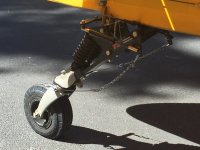
Got the chance to fly my shiny new T3 Tailwheel suspension. Blackrock has already done a great job reviewing it - not much to add except I concur! Really like the soft cushy feel. Even has a bit of grass hanging off of it, promise I didn't stage that! Great product and support from Dan D.
 

Attachments

  • photo2621.jpg
    photo2621.jpg
    1 MB · Views: 0
With a proper blade and solid edge guide, cut my second spar cap out of .125" yesterday. Like butter! Much, much better. Only 40-something more of them to go. :)

2da07cc65cea4fdde6069cd2a98a3e9d.jpg


da8413a48d819444797f8957651040c6.jpg


Sent from my iPhone using Tapatalk
 
They are so tempting! I just wish the would fit without needing to cut off the steering arms. It just seems so final.
 
The prop is an 82 in. McCauley C203. We had the tail raised to level to make it easier to work on the wings so it is sitting tail high in the pictures. The tires are deflated to sit the gear on hard shims to level the airplane left to right. The prop is long & the attitude may make it appear longer. It will have more clearance on the 26in tundra tires or the skis. You probably can see it getting close to your rocks.

I did a fair bit of research on STC's etc upgrading aircraft Cessnas Stinsons etc with the Continental IO-360 210hp. The STC's all have 80in & the McCauley application guide has the 80in or shorter for most of the Cessna's using the same engine. I inquired of a couple places that installed these engines for upgrades and spoke to an AME that did a few as well. The AME told me that the STC's called for 80in but he installed a longer one on his personal plane. He did the change under the radar and used a longer C203 prop that ran great. The consensus among the fellows that did these engine upgrades was that the 82in would work well. The MacCauley application guide had a couple hotter versions of Cessnas with the 82in prop. The 82in is peak efficiency for the rpm & just below Mach1 for this engine. The 82in looked like a good start with for the engine.
 
Last edited:
Looks great Glenn! The C170 STC allows a 82" C203 with the IO360. The Maule IO360 guru has installed several 82" props on Maules and a few 84" props. He says the 82" is about right but the 84" works well too. We are planning to use a 82" but if I have to buy a new one I'm buying a 84".
 
Whee. Thank you. We thought about going 84 as well but arrived at the 82”. I did not know a what over length prop will be hard on the crank and bearings. No one could tell me either. I think the 82in will work good for you.

Our engine is an IO-360G from a Cessna 337. One fellow that did the 82in upgrades said that we could go longer being non-certified. I asked what length & what was too long for the engine. He was not sure. Then said it likely was best not to get too extreme. The 84in at full rpm has a tip speed exceeding thrust efficiencies speed. http://pponk.com/props/#1463774934977-1d7f57b4-6b2b
This is interesting read on prop thrust values. http://pponk.com/props/#1463774935085-a6c14c04-3b8d
The Continental IO-36OK series has the heavier crank and bearings that in the Cessna is 195hp engine but the Isham STC boosts the engine to the std 210hp and uses an 80in prop. If any engine can take a long prop the K series should. The XP modifications used 82in for most of the IO-360 engine series but there are not many around as the owner had financial and regulatory issues. The XP STC's covers both 170's and 172. I could not find enough info on the XP's. One AME put on a longer prop said his neighbours hated it. Our flying club had a member with an over length prop that was loud that caused complaints to the flying club & the police.

It has been a long time since I had my head in these things but I know there are Cessna IO_360 variants which may be the French version that used the 82in prop.
The IO-470J is 225 hp and a stronger engine that uses the 82 in at 2550 rpm. The typical IO-470 is 260hp/2600 rpm with the 88in prop. My partner wanted to start at 88in but that was too excessive.
The 82in prop is in the maximum thrust efficiency range for the rpm. HP is hp when it comes to a fan, pump impeller or prop. Longer prop finer pitch will consume same hp as slightly shorter prop with wider pitch to move the same air with the same hp.

I had a project with a large prop fan that ran for years that suddenly let go. It literally let go with fragments through the fan casing in every direction including the outside wall. The fan bent a 4 in shaft. It was a good example of what happens when a prop fan gets unstable. Adding an inch to a fan blade at same rpm draws a lot more hp and it is not a linear calculation. I think it best to have a fan or prop to run at max efficiency and as stable as possible for a reliable and safe operation.
We decided at the outset that we would be experimental in name and build to certified or better standards. The 82in prop is the upper limit for the engine with a known history .
The 82in was a matter of the better compromise for optimum efficiency & reliability. In the end it is what a person is comfortable with.
 
Last edited:
Completed my tailwheel training in my 100-hp 1965 Citabria 7ECA, and got the CFI endorsement. Celebrated by flying solo for an hour in the 98°F heat, doing stop-and-go landings with an 8-knot direct crosswind, Keep imagining how much better this will be in my Patrol, when it is finished! Can't believe I waited so long to have this fun in my life!
 
Last edited:
No Title

Hope everyone is enjoying a great Fourth of July weekend! Brent and I got in a little Bearhawk time today. We rehung the engine a night ago and it went WAY better than expected. So our Saturday could be devoted to moving on to other things. Brent is hooking up and installing engine systems. I am in charge of the "Tinhawk" wood department.... which means I am installing the aerodynamic wood strips on the tail to help it be more effective. Since Brent is our resident Tin-knocker I guess I get assigned the woodwork! Anyway I am in the process of bolting the wood strips into our vertical and horizontal stabs. Here are a couple pics from today's work.

I am getting tailwheel (and little airplane!) instruction in a 1946 Aeronca Champ with 65 full HP! No electrical so hand propping and we use a handheld for radio work. Tomorrow I hope to get checked out for solo... we will see.
 

Attachments

  • photo2624.jpg
    photo2624.jpg
    2.9 MB · Views: 0
  • photo2625.jpg
    photo2625.jpg
    3.1 MB · Views: 0
Last edited:
No Title

It's all taped up! My small iron died (element burned out), so there's still ironing to do, but everything on the fuselage is taped. I had some minor concerns about the viability of straight tapes, on the upper and lower longerons, but 4" straight tapes worked fine. I wanted to avoid bias, because of the difficulty holding lines straight on the long stretches. The only bias tape on the fuse, is the vertical stabilizer, up the spine.
Next step would be shooting primer. I told my better half that I would take a break from the project, to catch up on grounds maintenance that I'd been ignoring. My place is looking pretty shaggy... That 'break' should take me to Oshkosh. Our Cajun Delegation is really looking forward to meeting with you guys on Tuesday! After a few days of aircraft immersion, it'll be full steam ahead!

Bill
 

Attachments

  • photo2627.jpeg
    photo2627.jpeg
    679.8 KB · Views: 0
  • photo2628.jpeg
    photo2628.jpeg
    514.2 KB · Views: 0
  • photo2629.jpeg
    photo2629.jpeg
    609.7 KB · Views: 0
It's all taped up! My small iron died (element burned out), so there's still ironing to do, but everything on the fuselage is taped. I had some minor concerns about the viability of straight tapes, on the upper and lower longerons, but 4" straight tapes worked fine. I wanted to avoid bias, because of the difficulty holding lines straight on the long stretches. The only bias tape on the fuse, is the vertical stabilizer, up the spine.
Next step would be shooting primer. I told my better half that I would take a break from the project, to catch up on grounds maintenance that I'd been ignoring. My place is looking pretty shaggy... That 'break' should take me to Oshkosh. Our Cajun Delegation is really looking forward to meeting with you guys on Tuesday! After a few days of aircraft immersion, it'll be full steam ahead!

Bill

Looks great! See you at OSH.
 
Finally got around to getting my stuff put away in the new place. I had a look at my router templates and need to come up with a way of repairing them to allow me to continue cutting my blanks (remember a few months ago my router caught the piece I was working with and launched it across the garage. The damage is on the the lightening hole, I am worried that with my repair it will not perfectly match the holes on the blanks I have already cut.
 
Thankfully, nothing relies on the lightening holes to be the exact same shape. Feel free to clean up the openings, ensuring they are smooth. As long as you aren't opening the holes a half inch or something goofy like that, I predict no ill effects. Can you refresh out memories as to the extent of the damage?
 
I had a look at my router templates and need to come up with a way of repairing them .

For a small nick I used baking soda and super glue, like one might use to repair an ultralight prop.

Sent from my XT1031 using Tapatalk
 
No Title

Just need to take it off the engine and airframe and do the finish welding. Pretty much wore a groove in the concrete floor walking back and forth from the mount to the grinder getting the ends to fit right :-)
 

Attachments

  • photo2635.jpg
    photo2635.jpg
    239.7 KB · Views: 0
Built a set of wing racks so I can get the wings out of the crates, and return the crates to Mark G.

Spent the rest of the day inside in A/C comfort, recovering from 3 hours outside in 98* heat. Whew! Gotta get my large workshop fan back from the folks I loaned it to!
 
Built a set of wing racks so I can get the wings out of the crates, and return the crates to Mark G.

Spent the rest of the day inside in A/C comfort, recovering from 3 hours outside in 98* heat. Whew! Gotta get my large workshop fan back from the folks I loaned it to!

You have a pic of the racks you built?
 
Bondo is great product for repairing MDF templates. It sands and routs real nice. You can slap it on a little thick, then re-rout it if you like using the master.
 
The covering is fun and greatly encouraging. After all the months spent working on the skeleton frame (I don't work fast...), it goes from bare bones to fully covered in two weeks! (Remember; I'm slow..). Nothing hard about it!
 
Bill,
Now that your this far down the road.......
Do you have a strong preference for the Superflite system over the Stits Poly Fiber?
I only have experience with the Poly Fiber system using Aerothane.

Any heat and humidity issues with Superflite system? I'm hopefully coming to the end of my long "TAB" journey on the fuselage. Hope to soon get into the start of priming everything. Hardest part is staying hydrated and not grounding out due to soaked with sweat. Gets my attention.
 
Last edited:
Well John, I could easily turn into a Superflite salesman. Like you, all my previous experience was with Stits process. After helping a local friend (who's covered several aircraft, with different processes), I was convinced that Superflite is an improvement. That being said, if you plan to go Stits, I have a BUNCH of Polyfiber stuff that I'll give you! Seriously, I have gallons of Polyfiber....... Yours for free!
 
One issue with using my on hand lumber was that it was a bit warped. The slings take care of ensuring the wings themselves aren't impacted, but mine didn't sit level on the floor - rocked from corner to corner. I solved that by purchasing screw-in casters, and using them the stabilize the rocking... As I said - my cost prior to the casters was $0.00, so spending $25 or so on them was no biggie.
 
Last edited:
Still installing the wood strips... ran out of nyloc nuts so once I am resupplied I can finish that! I did solo in the Champ today so that adventure is continuing. The rest of the family snuck out to the airport and was on the ramp to surprise greet me when I taxied back in after 4 circuits of the pattern! First solo in tailwheel for me. Fun for us today!
 
No Title

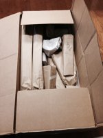
Now I've got plenty to do: picked up the pre-built spar package today ( & got the wing ribs), A couple months ago, traveled down to Austin with Mr. Parker and picked up the fuselage tube kit and ribs for the empennage. Been working a little on the tail section,, plan is to move to the wings, then fuselage. In the mean time,, guess I've got to unpack this stuff......
 

Attachments

  • photo2650.JPG
    photo2650.JPG
    2.3 MB · Views: 0
  • photo2651.JPG
    photo2651.JPG
    2.7 MB · Views: 0
  • photo2652.jpg
    photo2652.jpg
    94.4 KB · Views: 0
Last edited:
Prepare to be underwhelmed!

I've been planning on drilling out the jig pin and lightening holes in my master template for a while. In following the efforts of those that have gone before me, I elected to install drill bushings. I decided on using 3/16" steel brake lines. Conveniently, a #30 drill fits almost perfectly inside and a #12 bit is the perfect size for the outside diameter. I cut a couple with a tubing cutter, but quickly decided this would be better handled on a lathe. Really, I was just looking for an excuse to learn the very basics of using a lathe.

So I took the tubing to work and asked one of the machine shop dudes to help me out. Long story short, I wound up with a small pile of completely unremarkable drill bushings installed/hidden in my master template. I had a blast running the lathe and learning some very basic stuff.
 
Last edited:
More lathe work! Now that the master template is done, I need to make the cutting forms. To do so, I need the magic washers that Bob talks about in the "manual" that give a 9/16" and 1/2" flange. It was a slow day in the shop, so this was another opportunity for a lesson on the lathe.

Starting with the 9/16" flange, we took some 1 1/2" delrin rod (conveniently the required outside diameter) and put it in the lathe. We bored the center hole to 3/8", trued the O.D. and faced the end. We then changed to the parting tool and cut a 1/8" thick washer. I repeated the process for the 1/2" flange washer all by myself just like a big boy.

I'm now the owner of two white plastic washers that to the casual observer are completely unremarkable. They are, however, made to a ridiculously tight tolerance as they are accurate to the thousandth according to the calipers. Which is, of course, completely unnecessary. Ed, the machinist, was laughing at how carefully I was riding the tolerances but damn it, I wanted my washers to be the best they could be.

There's an old joke about measuring with a micrometer, marking with a crayon, and cutting with an axe. Seems about my speed...
 
Last edited:
I just can't give enough praise to you scratch build guys. I really appreciate your talent and drive. Chris, having your daughter working with you is so special. I imagine it blows away her friends that she's helping build an airplane!
 
No Title

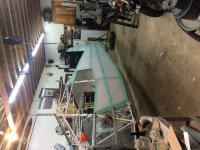
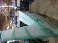
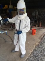
As promised to myself, returning from Oshkosh, I've begun the paint process. It's not just painting, but truly a much more involved 'process'. I have a nice air conditioned workshop, but wouldn't dare paint in there. So, all spraying and sanding is done in the hangar. For those who don't know, August, in Louisiana, is hot! The process goes like this; Sweat, spray, sweat, sand, sweat, spray, sweat, sand, repeat...

Bill
 

Attachments

  • photo2773.jpeg
    photo2773.jpeg
    1.3 MB · Views: 0
  • photo2774.jpeg
    photo2774.jpeg
    1.1 MB · Views: 0
You should borrow one of those Air conditioned EVA space suits from NASA. they may be a bit hard to work in but they would keep you cool. Don't worry about the $12M price tag. You could probably pick up one used and you would be the coolest looking painter at ten airport.
 
But John, I am the coolest looking painter at the airport!
MSwain, aren't you in Florida? Kinda warm there too, isn't it? Tee hee.......
Every day spent in the hangar is a day closer to the air conditioned shop! :)

Bill
 
I am in Florida, home of the 90+% humidity. I can sympathize. There must be many gallons of sweat on my garage floor. I think I take about 5 showers on a normal weekend day :)
 
I see what you did there...nice. I'm curious to see the routing to the tabs now.
 
No Title

Getting a start on the wings for the patrol. Will order the aluminum for the wings shortly, I believe the bottom, one piece skin is .025, but where is the thickness for the bottom skin listed, on the plans ?

Thanks
 

Attachments

  • photo2878.JPG
    photo2878.JPG
    3.6 MB · Views: 0
  • photo2879.JPG
    photo2879.JPG
    3.8 MB · Views: 0
No Title

Painted parts!
If all goes according to plan, fuselage gets base color tomorrow... And a visitor from the west!

Bill
 

Attachments

  • photo2890.jpeg
    photo2890.jpeg
    155.3 KB · Views: 0
  • photo2891.jpeg
    photo2891.jpeg
    147.1 KB · Views: 0
Whee, congrats on finishing the welding. Those tab installations seem to go on forever don't they?

Thanks Pat. Yes, those tabs are miserable and seem to never end. Now that it's all painted I'm sure we'll find some tabs we missed.
 
No Title

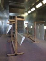
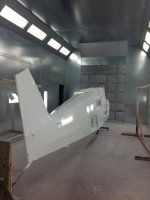
I told my wife that I'd been 'juggling balls' all week. Being ready to start spraying paint, I had to reserve time in a friend's paint booth. Then, I had to borrow an enclosed trailer to transport pieces, to and from the spray booth. Last, I needed to coordinate a painter. I've done a bit of painting, with mixed results. I'm great with primer, but there's about a 50/50 chance I'd have a couple of runs, with the color coats... Juggle, I did. Other than a single day's delay, the plan worked! There's another color to come, but the process is well under way!
Now is as good a time as any to express my appreciation for the wonderful friends around me! If any element of my plan fell through, she wouldn't be in paint. It's my sincerest wish that each of you guys be blessed with such a supportive group, to smooth your path.

Bill
 

Attachments

  • photo2893.jpg
    photo2893.jpg
    845.2 KB · Views: 0
Last edited:
I marked out the lightening-hole positions on my aileron-spar blank. Plans call for 3-1/8 diam hole on a spar that is 3-7/8 wide, theoretically leaving only 3/8 inch of web left above/below each nhole. That seemed marginally narrow for me, so I set my fly-cutter a few thousanths undersize and cut my first lightening hole. I was in too much rush (as usual) and cut my hole about 1/16 off-center. (see photo) There is not a full aluminum skin on the aileron, just the thin nose-skin, so I am worried about by aileron spar being strong enough. I adjusted my fly-cutter again, downsizing it again a few thousanths, and cut some more holes.

Anyone out there think I should start over with a new blank aileron spar?

Bergt lighteningholes.jpg
 
If I read your description correctly, plans call for 3/16" edge margin (3/8" divided by 2) above and below the lightening holes. At the hole that's off center the worst, do you have less than 3/16" margin? If so, I'd make another. If more than 3/16" forge ahead.
My $0.02

Bill
 
No Title

How does one lay out a straight line, from nose to tail? With a (Craigslist $100) rotary laser!
Now, more masking, prep and painting...

Bill
 

Attachments

  • photo2948.jpg
    photo2948.jpg
    1.1 MB · Views: 0
I'm pretty excited about how my Luscombe trim handle is turning out. Think I'm going to really like it.

174b23719a9f44ac6c1fcc0b3d228da3.jpg
 
Nice! It does look like it would be friendlier to operate than the hand wheel, particularly with a less sensitive trim setup at the rear end.
 
Looks great, works well over all the peaks and valleys, I used the laser level for the stringers also. George
 
Nice! It does look like it would be friendlier to operate than the hand wheel, particularly with a less sensitive trim setup at the rear end.

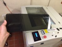
I used a 6 tooth sprocket instead of a 9 tooth like the BH wheel uses and I installed the PF trim system so I think it will be a bit less sensitive than the factory system.
 
No Title

Today we put the wings on 240BP. Still a lot to do--flaps/ailerons need to be installed and hooked up, wing tips, lights, fuel lines and all that stuff. But after 3yrs., 7.5 months and two Patrol projects--The Wings are ON one of them with the other soon to follow--WOOHOO D-n-D Patrols-240BP & 241BP
 

Attachments

  • photo2990.jpg
    photo2990.jpg
    5.3 MB · Views: 0
No Title

Yea, that's a drive for you. But as always your welcome anytime! One of these days we'll fly them up your way! We are waiting on parts for my wing before we put it on. They should be here Friday--scat tube for the air vent and about 60 feet of 20 gage wire. Donna
 

Attachments

  • photo2994.jpg
    photo2994.jpg
    2.4 MB · Views: 0
Back
Top