Tell us what you did today on your Bearhawk Project

Mrs. Thomas, my second grade school teacher, had a sign on her class room wall, "Taste your words before you spit them out." Obviously I failed to do that and for that I apologize. I know nobody is getting rich off any of these forums and most don't even break even but I feel how I feel and I guess my mood was just right that I hit the enter button this time. Again, I apologize.
 
WhooHoo I finally got the landing lights cut into my wings and got the lenses installed!

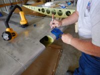
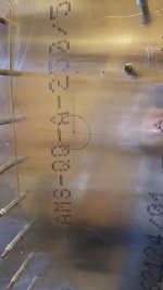
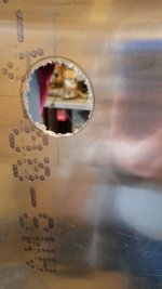
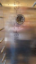
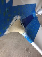
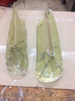
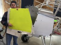
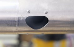
I have enclosed some pictures and am going to try to explain what I was able to accomplish that I hope will be helpful to someone else. I cut four holes in the leading edge of the wings, two for landing lights and two for taxi lights. Hole size is 5'w x 6.5'L for all four. I created a template from which to mark the hole and positioned it so topside from the center line of the leading edge was 3 5/8" and below the centerline was 4 7/8". I wanted a longer opening on bottom side of the wing for the taxi lights.
The Plexiglas I used was 1/8" and I cut it to 6"w x 9"L and shaped it over the leading edge of the wing using spring clamps and a heat gun.

Pic 1 is the completed lenses.

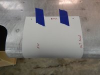
Pic 2 I have drilled the holes and am using masking tape doubled to pull the lens forward and marking the holes for the screws. (6-32 1/2" min.)

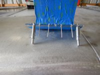
Pic 3 is the lens with the 6-32 nut plates installed.

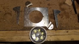
Pic 4 is my template

Pic 5 is one of the cut-outs

Pic 6 shows how I put the nut plates in place. While two pop rivets will hold the plate with the nut plates I found that I needed the extra support when installing screws.

DSCN0285.JPGDSCN0283.JPGDSCN0278.JPGDSCN0274.JPGDSCN0276.JPGDSCN0277.JPG
 
No problem whee, I'm not offended and would always rather folks feel comfortable with speaking freely than have them feeling like they can't say something because they don't want to hurt my feelings.

There are several reasons for not elaborating on the servo installation here. First, I need to be sure that the installation works, lest I lead someone else down the wrong path. Second, if the forum was the best place for it, then this thread probably wouldn't be. The third is that I'd rather have the content in the newsletter. I think less about trying to sell more newsletters and more about trying to provide better value to the folks who have already paid for it, but I realize those two may be the same thing.

The intersection of free information and monetized information gets sticky. This is something that I think about a lot, and have tried to find good balance with. That thinking leads me to believe that whether or not information is free to consume, it is never free to produce. In a setting like this, the information is generously donated by the folks who post it. It is also subsidized by other participants who pass it through an editorial process by speaking up when it seems to be wrong or unclear. It is also subsidized by the provider of the venue, which in this case is Bearhawk Aircraft and BH Services LLC. We have some really generous people who donate a lot of time and effort to help fellow builders, which is great. The minor costs of keeping the lights on (so to speak) are insignificant when compared to the value of these efforts.

When we took over the Beartracks venture from its last publisher in 2012, I talked at length with several builders to try and make a good plan going forward. Some made the very good case that the newsletter content should be available for free, including back issues. (Safety updates, while included in the newsletter and sometimes elaborated on there, should always be free). Some made the very good case that if we are charging for the newsletter, we should not expect the writers to donate the content. We face the reality that as of now, the web hosting company, security certificate company, and domain registrars do not provide their services for free. Who should incur those costs, and at what stage in the overall information delivery process? We arrived at the following compromise: we halved the cost of the pdf newsletter from $16 to $8 per year. We started paying writers a small amount to offset their trouble, though it is never enough to really pay what the content is worth, at least to me. In an effort to increase the value of the back issue content without increasing the price, we manually input all of the past issues into a database-driven venue that allows for easier access and interaction. (This was a project of hundreds, not tens of hours). Keep in mind that while the content in that archive is far from perfect and very far from complete, all of it has at one point passed under the eyes of Bob Barrows and received his nod, and much of it has received similar approval from Mark. Mark sees much of what is on the forum and will speak up if he disagrees, but it is safe to assume that essentially none of the content here has Bob's oversight.

The additional cost of producing the newsletter is in the effort it takes to rustle up content, assemble it, send it out for various approvals, and distribute it to the subscribers. Those things require about as much time as managing subscriptions, handling changes to addresses, etc. For the few folks that still subscribe to the paper version, we maintain an expensive color laser printer, buy stamps, envelopes, etc. The extra $10 per year doesn't cover the additional cost of the paper version of the newsletter, but being that we have so few people using that option, I'd rather subsidize that minor loss and not have to increase the yearly rate, which already seems so high.

To give you some napkin-level math about the financial situation of the newsletter, half of all subscription fees go to paying the writers and the expenses related to internet delivery. (I'll add that when we can't get enough writers to fill an issue, then I have to write articles to make up the difference, though I don't pay myself for those articles). That leaves about $1000 per year. About half of this is consumed by subsidizing the other Bearhawk internet ventures like the message board, and in paying the expenses related to housekeeping for the LLC. The rest, if divided by the approximate number of hours devoted to the newsletter alone, pays me at a rate of around $5 per hour, unless it instead covers some one-time expense of the Bearhawk-related stuff, like expenses to keep the store going, etc. I don't ever actually pay myself that money, it just sits in the LLC's account, and somehow finds its way to some other expense as time goes on. I have the good fortune of having a very well-paid day job (at least as of now) and without getting into specifics, let's just say that a year's worth of Bearhawk work pays less than a couple of hours of day job work. I say this not because I'm asking for sympathy or compliments, but rather just to make the point that while, yes, money does change hands in the newsletter, the few things that I help coordinate in the BH community are labors of love. I do them because as a builder, I want for them to be done, and it seems that nobody else wants to do them.
 
Thanks Jared Volunteer labor is hard to come by, and is more passion than anything, thanks for keeping the dream alive.
 
To me the splice measurement on BH4 plans are not clear. Do you have any insight?

You can measure the splice plate with a ruler since its full-size in the plans. What most have done is make a photocopy of the plate from plans, cut it out, and glue it to the piece of metal as a guide and cut from there.
 
No Title

Hi all,

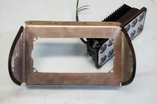
I decided to go with PAR36 4.5" LED landing and taxi lights from AeroLites on my 4pl Bearhawk. The trick was, how do I mount these so that a.) I can adjust them after assembly, and b.) the mount doesn't weigh a ton (or tonne for us metric types).

This is what I came up with. It is similar to the Duckworks kit I installed in my RV-8 15 years ago.

I made a mount plate, two side angles, and two holder tabs, all out of .032 2024T3 . The distance between leading edge ribs is only 7", so I don't think there will be any issues with flexing of the plate.

Once everything was primed, I riveted it together and then started the mounting process.

First, I figured out the movement limits of the upper side angles where the set screw was going to go. I flattened the lightening hole flange in that area and drilled a #40 hole at the point where the light mount could be either at 0 deg (straight ahead), but still give me lots of down angle if I need to adjust it that way.

I then drilled the bottom pivot holes (using a #40 drill) and inserted clecos. This allow me to now rotate the whole mount while marking the track for the set screw with a Sharpie.

I dismantled everything, cut the set screw slot in the side angles with a Dremel, and installed K1000-08 nutplates on the ribs for the pivot screws and the set screws. I remounted everything and I now have a landing/taxi light mount that I can adjust for elevation easily after assembly.

My description of the steps probably sucks, but I think the pictures are relatively self explanatory.

Cheers
 

Attachments

  • photo3306.jpg
    photo3306.jpg
    1.2 MB · Views: 0
  • photo3307.jpg
    photo3307.jpg
    1,008.9 KB · Views: 0
  • photo3308.jpg
    photo3308.jpg
    861.6 KB · Views: 0
  • photo3309.jpg
    photo3309.jpg
    957.2 KB · Views: 0
Very nice! After looking at your pictures I can see where this is definitely one place where scratch built has and advantage over quick build. You didn't have to work thru a 5" X 6.5" hole to do your insulation. It's awesome how clean and simple the bracket and install looks. GREAT!
 
Mornin' all

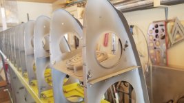
I had been dreading the whole process of cutting the fuel tank filler neck holes in my wing skins. I was really worried that I would mess something up and cut the holes in the wrong spot (like that NEVER happens, right?) and wind up trashing some expensive sheets of aluminum. Well, turns out it was really easy and I did both holes in my left wing (I have an Aux tank) in a little over an hour and they both turned out perfect.

I was a little leery about using some of the methods I had read about, including the one about smearing some kind of liquid/putty/whatever on the rim of the filler neck and then pressing that against the inside of the skin. I didn't think that would be very accurate.

This is what I did (your mileage may vary, batteries not included, objects in mirror are closer than they appear...)

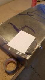
1. I took a square of paper and drew a 2" circle on it.

2. With spray contact cement, I attached the paper perfectly centered on the filler neck. I then put duct tape on paper facing up (towards the inside of the wing skin) along the side closest to the edge of the tank.

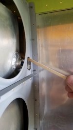
3. I then positioned the tank where it needed to be (vertically and horizontally) and then used a long wooden coffee stir stick to reach through a lightening hole and press the tape to the skin.

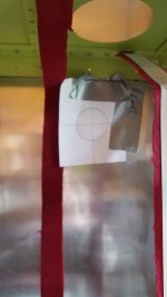
4. The tank was then removed. The duct tape easy overcame the stickiness of the contact cement, so the square paper template was now stuck EXACTLY where I needed to drill the hole. I drilled a #40 hole through the center so I could mark the hole on the top side of the skin.

5. Using a #40 drill, I worked my way around the hole and then used a Dremel tool and file bit to remove the waste in the center.

6. I used a spiral bit in an air die grinder to round out the hole and make it 2 1/4" in diameter (1/8" all the way around the hole). Why not go straight to 2 1/4" at first? In case I buggered something up; you can't put material back in :-)

That's it. Quite easy actually.

Cheers
 

Attachments

  • photo3445.jpg
    photo3445.jpg
    1.1 MB · Views: 0
  • photo3446.jpg
    photo3446.jpg
    993.8 KB · Views: 0
  • photo3447.jpg
    photo3447.jpg
    966.1 KB · Views: 0
  • photo3448.jpg
    photo3448.jpg
    872.7 KB · Views: 0
  • photo3449.jpg
    photo3449.jpg
    1 MB · Views: 0
  • photo3450.jpg
    photo3450.jpg
    986.6 KB · Views: 0
  • photo3451.jpg
    photo3451.jpg
    975.1 KB · Views: 0
  • photo3452.jpg
    photo3452.jpg
    1.1 MB · Views: 0
  • photo3453.jpg
    photo3453.jpg
    999 KB · Views: 0
I had been dreading the whole process of cutting the fuel tank filler neck holes in my wing skins. I was really worried that I would mess something up and cut the holes in the wrong spot (like that NEVER happens, right?) and wind up trashing some expensive sheets of aluminum. Well, turns out it was really easy and I did both holes in my left wing (I have an Aux tank) in a little over an hour and they both turned out perfect.

Nice technique! Congrats on the perfect hole!
 
I like the method! I wonder if the forum administrator could copy this and post it in Tips & Techniques section of the forum for future builders. It hidden here in this thread, and may be difficult to find in the future.
 
The forum administrator has left the building, but one of you is welcome to do it! Or better yet, get Mark to write it up for Beartracks, which will get it onto bearhawk.tips. I'd like to have a public part of bearhawk.tips where we could have things like this, but don't foresee having time to get it done any time soon. If anyone is interested, I can get you set up with the credentials.
 
Two days ago we took the cowling off my plane. Found a new Gremlin. Although sad that I have another one, happy to report it’s the equipment and nothing to do with the builders or the kit/airplane. Tach went wacky during a flight in cruise. Trouble shooted & found the R- P Mag to be the culprit. Something in the coil or circuit board went bad and caused the #3 & #4 cyl to not fire on the bottom plugs, which apparently caused the signals to the Dynon Tach to mess up. The P-Mag tech had us do some things to test and came back with the fact he has seen this before, send it back. So if anybody has P-mags and your tach goes wacky, it should show up in a mag check. Sent it back, so I’m grounded again!! Hopefully it is the problem and this will fix it.

As far as flight reports the plane is still performing great. Getting 1200 or more FPM up on a 85 MPH indicated take off climb and cruising at 142 @ 75% power. Also either I am getting stronger or the flap spring is getting weaker, but pulling the 3rd notch at between 60/65 is not a problem. I’m really impressed with the landing gear. It’s holding up amazingly well in my opinion. ;-)
 
Last edited:
This evening we took one of our roosters up to my friend Joe's place. I posted a video a while back of landing at his strip: https://www.youtube.com/watch?v=GCFEkLYMWOw
He's been grading ever since then and has made the runway a little longer, which is nice. It would have taken us an hour to drive, but it only took 15 minutes to fly up there. The girls got a serious case of the sillies on the way back.
 

Attachments

  • IMG_20170531_202948.jpg
    IMG_20170531_202948.jpg
    6.7 MB · Views: 0
  • IMG_20170531_200301.jpg
    IMG_20170531_200301.jpg
    8.2 MB · Views: 0
  • IMG_20170531_190547.jpg
    IMG_20170531_190547.jpg
    10.3 MB · Views: 0
Jared, glad I'm not the only one who fly's birds in their birds! The neighbors @##@## cat killed my nesting bluebird the other day. The new babies found a new home at the Chintimini wildlife rescue ranch in Corvallis OR. So, I had the honor of giving them their "first flight". ;-) Donna
 
Greetings all! What I did today is join this forum! Baby step 1. I've been researching the right plane for me and have decided that the Bearhawk is the one! I bought a kit that was started by Dan Christ in San Antonio and have brought it home to Slidell, Louisiana to start the process. I would really appreciate finding out who has the nearest completed 4 place so that I can come out and take a look at it. I haven't seen one before. :) Didn't need to, it's pretty obvious from all the reports I've read that it's a great heavy hauling plane! The end result will be a bush plane hunt in Canada / Alaska. I'll be reading the posts and starting to get a feel for where to start. Thanks!
Brad
 

Attachments

  • photo3521.jpg
    photo3521.jpg
    5.5 MB · Views: 0
Hi Brad. No 4 place, but I'm flying a newly completed Patrol, in Grand Coteau. Still in phase 1, so Slidell is out of bounds, for now.

Bill
 
WOW......want to take a vacation to the Seattle area and do some more painting!!!! Very nice.. Love the design.
 
Packing it up!

The Airplane Factory is a sea of boxes and stuff as the shop gets loaded into the big semi sitting at the end of the driveway. And to think, just two days ago I could see the floor.

By Saturday, all of this will be in Milwaukee. By September, I'll probably finally find everything so I can get back to work.

1f22fe0028d589e3c1da3eb083881184.jpg


And Buddy is sitting here calmly watching his house disappears around him.

038f5a7c4649d4da4e02ad3b5af9a6b4.jpg
 
Last edited:
Im in Lafayette, LA and have been to see Bill's Patrol, Its a beauty! Will definitely inspire your build (it sure got my butt back in the garage and working on my 4-place again)
 
Thanks for the comments folks. As far as the painting all I can take credit for is running a sander and finding a great painter. I got lucky and found him thru my EAA chapter. He gets lots of practice working in the sheet metal and paint shop at NASA. You get a lot of practice painting the Guppy. LOL
 
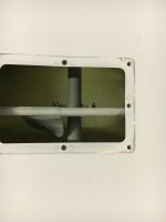
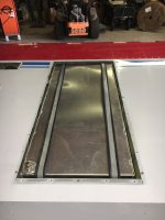
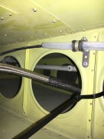
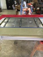
Started installing fuel tanks today Got the left wing tanks installed but not after I discovered I had built myself a trap. When installing the transfer fuel line from the reserve tank I inadvertently ran the line across the center of the inspection panel for the flap springs. As I found out I would need hands and arms the size of a 5yr old to work around that line. I wound up pulling the hard line and installing a flex line. The hard line would have worked if I had gone on the top side of the flap spring bar and put a couple of 90s in the line. See attached pics. IMG_1738.JPGIMG_1730.JPGIMG_1734.JPGIMG_1731.JPGIMG_1735.JPG
 
I found my EFIS electrical connector was loose. This caused alternator wine and wig-wag light clicking. Check your connectors on your EFIS and Engine monitor boxes. They are usually not safetied in any way. Use locktite I guess.
 
Installed my gear leg / fuselage fairings. I have Bob's upper and lower strut fairings, also. Will use the upper ones, but not decided about the lowers.

Up to 23 hrs and flying great.

Bill
 

Attachments

  • photo3578.jpg
    photo3578.jpg
    59.4 KB · Views: 0
  • photo3579.jpg
    photo3579.jpg
    68.1 KB · Views: 0
  • photo3580.jpg
    photo3580.jpg
    72.8 KB · Views: 0
  • photo3581.jpg
    photo3581.jpg
    410.1 KB · Views: 0
  • photo3582.jpg
    photo3582.jpg
    417.2 KB · Views: 0
I love the diamond tuck look. Can you give more details to someone that knows nothing about upholstery (but my wife sews). Materials used, methods etc.

Doug
 
Hi Doug, Yes I also love it and the vintage look that goes with it. I used ripstop light canvas that they use for light tents with 6mm foam and linen cloth for the inside. drawn all the lines parrallel on a cut out panel and sewn on the lines, you need to do every second line and change direction everytime. the backing is aluminum with 2,5 inch lightening holes cut in them, I glue the sewn-up panel to the aluminum. I will add more photos
 
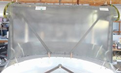
Cut and fit my windshield and skylight. Windshield was the untrimmed version. Believe I ended up taking about 3 inches off the bottom. Skylight is 1/8th solar gray lexan, should help keep the heat out. When trimming your windshield make sure to clamp the sides to the tubing. Initially I didn't, they were about 3" from the tubing. Once I clamped them it changed the shape at the bottom. I ended up with a nice fit at the leading edge, base of the windshield ended up 1 1/2" in front of the diagonal tubes.This was something I didn't want to attempt until the wings were mounted.
 

Attachments

  • photo3685.jpg
    photo3685.jpg
    1.3 MB · Views: 0
Last edited:
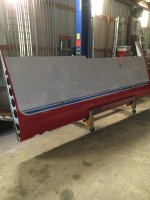
We tried to get the plane in the paint booth this weekend but we didn't quite make it. We are racing the weather and I'm not sure we are going to make it; seems we have skipped fall and gone from summer to early winter. Hopefully we will get a few warm days so we can get the fuselage painted.


7e4c10f55b1e9f9b6a020bda76777b61.jpg
b68eb943796666b973deda8894c105b8.jpg
 
Whee, I'm sure you've told us already, but I don't recall. What covering system are you using?
A very exciting stage in the process!!

Bill
 
I updated my blog (basically what I'm using for a build log) imported my electrical system drawing into draw.io, and sorted out how I'm going to do the VOR antenna. My work nights are Tuesday and Thursday night, so during the week I'm usually updating documentation or figuring out how I want to tackle something. I think figuring out what I want to do take as much time as doing it, or perhaps more.

Nice hangar!
 
Hey Whee, looks great to me! There's no 'right way' or 'wrong way'. My thought process was to paint the small pieces first. I figured it was easier to sand and re-spray screw ups on small pieces...

Either way, getting the fuse painted is a big milestone!!

Bill
 
Thanks guys. We used Stewarts and like it. Any issues were self inflicted. We painted the fuselage first because the weather was closing in on us and I can heat my garage to paint the small stuff if necessary. Also, my dad can wire the fuselage while I work on covering/painting everything else.
 
I'm with Bill. It would have been sweet to share this experience with my dad. Now at the rate I'm going it's looking more like I will be the dad.
Fuse looks great to me Jon!
 
Hi Chewie, I am in the process of cutting and shaping the spar attach fittings and wanted to ask what the edge distance was at the rivet line under the spar caps? If I use the drawing I get .25 inches.
 
I don't remember what the rivet spacing would've come to. Even with perfect precision I think it was coming up short. In fact, if you go by the plans every attach angle will come up short because they are 5/32 rivets at the caps and the angle is only 1/2" wide.

What I would do on the fittings, since they are a pain to remake, is just rough cut them and lay them on, get the positioning right, then drill thru undersize, and that will tell you exactly where those rivets will pass through the fitting. Draw a clearance circle of appropriate diameter around each hole, and when you finish your fitting to final size keep it clear of those circles!
 
Finely got back to working on the plane today. I finished the baffle kit as far as I can till I put the cowling back in place. I also put in a 4 position fuel valve. I had a single ball valve for my fuel but after conversations with Bdflies he convinced me to change my setup. It always amazes me how long it takes to accomplish some of these tasks. I attached a couple of pics of things.
 

Attachments

  • IMG_1879.JPG
    IMG_1879.JPG
    1.6 MB · Views: 0
  • IMG_1877.JPG
    IMG_1877.JPG
    1.7 MB · Views: 0
  • IMG_1881.JPG
    IMG_1881.JPG
    1.9 MB · Views: 0
  • IMG_1878.JPG
    IMG_1878.JPG
    1.5 MB · Views: 0
Last week I reamed out the engine mount attach bushings and attached a temporary plexiglass-glass firewall templet. I will use the plexiglass firewall to plan all the firewall penetrations and plan mounting of various accessories, fittings, brackets and doohickies.. At the end, when all the stuff has been properly located I will have a template for the final drilling of the permanent firewall.

Al Lux and Mark G. gave me some advice on reaming the bushings and it went real smooth. I acquired reamers from Aircraft Tool Supply, they are a Michigan Company. It was my first time using a reamer....as a Novice searching for a Reamer I got overwhelmed. HSS, cobalt, straight flute, spiral slate, hand, machine,...this list goes on. Heck, I don't know...I just want a reamer!

I bought the one needed for the Engine Mount bushings of course, plus a smaller one I will need when the wing attach drilling gets done. They worked great, and a reasonable price. I also used Boelube during the reaming process. If you've never heard of it, get familiar with it. I am frugal. Its $4 for the 1.6 oz stick of Boelube. It will last a life time, improve quality, save scores of dollars in consumable drilling costs, and hours of time drilling. Don't skimp when piercing metal.

Reamer: https://goo.gl/be9Z9G
BoeLube: goo.gl/BEMded

Click image for larger version  Name:	IMG_4235.jpg Views:	1 Size:	1.08 MB ID:	33562
 
Last edited:
Thanks, just the way I like it too, I know its out of fashion, I just love to experience it the way it was 50 years ago. enjoy
 
That looks fantastic.

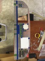
I worked on my skylight a bit. Making the standoffs and welding saddles in them. I hope to have the thing completely mocked up and tack welded this weekend. Then I think I'm going to build a welding table to mount my new tools to.
 
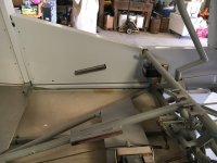
Finely got back on the plane after the new year. I finished the rack for my instruments behind the panel. I made this with all light aluminum angle. Back rail has 1" angle with 1/2" x 3/4" angle sandwiched and riveted with a 1/16" gap to slide the angle that holds each instrument module. that is what anchors the back of the modules without having to put any screws in the back.
On the front edge I used another 1" angle for the modules to rest on with another 1/2" x 3/4" angle to capture the front of the modules. I cut some slots in the small angle and installed 8-32 nut plates in the 1" angle to secure the small angle. Hope the pictures explain what I tried to. IMG_1997.JPGIMG_1996.JPGIMG_1999.JPG
 
Finely got back on the plane after the new year. I finished the rack for my instruments behind the panel. I made this with all light aluminum angle. Back rail has 1" angle with 1/2" x 3/4" angle sandwiched and riveted with a 1/16" gap to slide the angle that holds each instrument module. that is what anchors the back of the modules without having to put any screws in the back.
On the front edge I used another 1" angle for the modules to rest on with another 1/2" x 3/4" angle to capture the front of the modules. I cut some slots in the small angle and installed 8-32 nut plates in the 1" angle to secure the small angle. Hope the pictures explain what I tried to.

Thanks for the pictures, that is a more elegant solution than I have come up with for mounting all the garmin boxes.
 
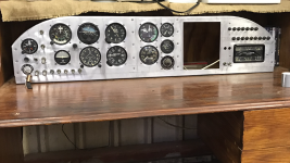
So, removing four screws is all it takes to remove any LRU box....Very Innovative! Tell us about your instrument panel, its removal, and how you will get access to these boxes that sit behind it. It looks like you have a 1" flange on the perimeter of the instrument panel and have removed the remaining material of the face of the panel.
 
Brooks: It actually is five screws but who's counting. LOL You can loosen the screws on the front and lift the angle they hold and slide any module out for service. My panel isn't cut yet but I can post a picture. My plans are to put 4 clamps around the lower panel support tube to attach them to the panel. The top edge will screw to that 1" flange you see in the picture when I get the nut plates put in. I am also mounting my throttle, prop, mixture, carb heat, cabin heat, and primer on separate cutouts that will screw to the panel and be able to be dropped out of the way when I need to rotate my panel down ( on the clamps from earlier ) for service. I'm putting two Garmin G3X displays in the panel ( one 10.5" n one 7" ) along with a TruTrac Auto pilot. I have left 4" between the rack and the panel.
 
The hardest part was getting the slots that you can see cut in the back rail and the piece of angle between the tubes must be trimmed about 1/4" so it will sit flush on the tubes. I don't know if you can tell but I riveted a flat support of 3/4 x 1/8 to strengthen the cut outs. I also had to put pieces of that support material on the front rail to make it sit right.
 
For some reason your description reminds me of watching a mechanic do a quick fix on B-727 decades ago. Some gage was inoperative in the engine instrument panel. His screw driver applied two quarter turns to a couple dzeus fasteners at the top of a panel, the entire panel with probably eighteen 2 1/4" gages hinges down and a grounding strap held it in perfect position for his repair. (Boeing thought of everything.)

The opened panel briefly exposes a huge array and catacombs of mysterious going-ons behind "the Curtain". Dark, dirty, scary, yet a wonderment to ponder...what goes on back there? Are there mice? Bugs? Bats? Money? hidden treasure?

He re-racks a cannon plug, or swapped gages, then closed her up, and we were good to go in minutes.

Tell me, are you going to include a ground strap in your design?
 
Last edited:
I still wonder if pointing the exhaust tips away from the cockpit isn't a fantastic idea. Pointing them down Pi$$es off your neighbors. Pointing them sideways? Not sure. But it is away from the cockpit.
 
The boot cowl skins are all cut, formed, fit and clecoed in position. It was a big job and I enjoyed every minute of it.
Click image for larger version  Name:	BootCowl.JPG Views:	1 Size:	1.37 MB ID:	36192
My top skin is three pieces which varies from the plans and the kit. The top center skin is about 18" wide. The two top-side skins then wrap around below the bottom of where the windshield will join the cowl. Others have also done this...The lower joint will allow easy removal of the side boot cowl skins.

I put a curve in the top skins using a sheet metal roller that my local EAA chapter has laying around. I never have used one before....pretty cool, worked real nice, easy to learn.
______

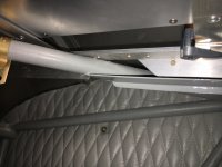
I made a poster board pattern of each panel. Fifty Cent poster board form the dollar tree was too flimsy, but spray gluing two pieces together made for a nice stiff panel that resembled the stiffness of .025 sheet aluminum. My first pattern (White/yellow) was made out of smallish pieces of poster board...fitting around every little nook and cranny and taped to each other. Packaging Tape was everywhere and it looked like a mess. I made a second neater pattern from the preliminary pattern which required additional trimming. Fabricating the sheet metal from the pattern was a familiar task done with confidence and without too much trouble after tracing, cutting out, and fitting the two patterns.
Click image for larger version  Name:	posterboard pattern.JPG Views:	1 Size:	211.4 KB ID:	36193
I positioned the joint of the top skin and the side skin to be a visual extension of the bottom of the side window. The line I am trying to create is like the paint line that runs under the side window of Bob Barrows' Patrol. The joint of the upper and lower engine cowl will also run parallel to this line.

Click image for larger version  Name:	IMG_3707.jpg Views:	1 Size:	2.04 MB ID:	36194
 
Last edited:
So you hold the top side skins on with nut plates, allowing easier access to avionics and electrical? I was wondering how you would work on that without laying on your back under the instrument panel.
 
One could make an access thru the top. I like the idea of making the instrument panel with removable sections and accessing the area behind the panel from the front, or from the sides with the side boot cowl skins removed. Top access would be very easy to install at this point.
 
One could make an access thru the top. I like the idea of making the instrument panel with removable sections and accessing the area behind the panel from the front, or from the sides with the side boot cowl skins removed. Top access would be very easy to install at this point.

Yeah, I was going to make the structural part of the panel a frame, and have a cosmetic (CF) sandwich laminate "face" screwed in place so I can access electrical and electronic stuff. Maybe 1 piece, or maybe 2. It would be difficult or impossible to do with a panel full of steam gauges, but mine have 1 EFIS and 2 "panels" of switches. Might as well use the empty panel space to access the area behind the panel.
 
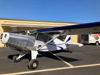
Well, I didn't take any pictures of the auxiliary tank door that I made on the weekend, but here is a picture of the Maule M5-235C I bought on Friday :-) I sold my RV-8 before Christmas and was going to wait until the Bearhawk was done, but that is still a few years away. When I saw this one for sale on Trade-a-Plane, and it was already in Canada, and was IFR certified (I want to get my ticket), I had to check it out. I went out to Lethbridge last Friday (from Ottawa for those of you who care) inspected it, went through the logs, and then flew it. If the Bearhawk performs half as well when it is done, Woo Hoo!

I've now joined the "Bought a Maule while I build a Bearhawk" club. Maybe I'll see you other members at Osh this year :-)

Mark
 

Attachments

  • photo4509.jpg
    photo4509.jpg
    259.8 KB · Views: 0
Finished up a couple items today. Easy one was Cessna style vent installation. I bought C185 flange and elbow pieces on EBAY. Bought Cessna vent tubes from aircraft spruce. Used a piece of 2" x .049 aluminum tube to tie them together. That worked great as the al tubing was a tight fit in the elbow and the vent tubes were a tight fit in the al tubing. When I reinstall the wings will just need to cut a 2" hole in the interior panel and insert the vent tube into the al tubing. Will glue the flange of the vent tube to the interior panel to keep it from working out as the vent portion is opened. Probably a tight enough fit that it wouldn't come out anyways. I used Bob's template in the July 96 Beartracks to locate and cut out the wing opening. The Cessna nose flange when fitted to the Bearhawk wing leaves about a 1/8" gap a little below the chordline. I used silicone sealant to seal this area when I riveted the flange in place. The nose flange has to be moved out about 1/2" on the elbow piece to allow the vent tube to fit through the lightning hole in the rib. Fortunately there was enough material on the elbow piece to allow that.
 

Attachments

  • photo4521.jpg
    photo4521.jpg
    1 MB · Views: 0
  • photo4522.jpg
    photo4522.jpg
    1.5 MB · Views: 0
  • photo4523.jpg
    photo4523.jpg
    1.1 MB · Views: 0
Last edited:
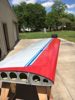
Completed installation of Aerosun landing lights in the wing leading edge. Took me awhile to decide how I was going to do this. I decided to semi-permanately install the lexan lens in the wing and install the light and housing through the lightening hole in the wing tip rib. That allowed the smallest possible cut in the wing. The opening is only 2" deep into the leading edge. Of course that means any future light maintenance will require removing the wing tip. Hopefully wont be an issue with the led light. I used permatex windshield and glass sealant to seal the lexan to the wing. I tested it first for compatability Will be possible to remove and replace the lexan in the future if necessary. I formed a couple extra lens just in case. I installed the light angled 5 deg down from the wing chordline. This makes it 3 deg down in level flight. I'm hoping it will be adequate for a taxi light but not sure. I will install a taxi light in the nose bowl if I have to. I'm happy with how the installation turned out.
 

Attachments

  • photo4524.jpg
    photo4524.jpg
    1.7 MB · Views: 0
  • photo4525.jpg
    photo4525.jpg
    1.7 MB · Views: 0
Back
Top