Bearhawk Aircraft Bearhawk Tailwheels LLC Eric Newton's Builder Manuals Bearhawk Plans Bearhawk Store

Announcement

Collapse
No announcement yet.

Wing Root Flap Cable & Fuel Lines

Collapse
X
 
  • Filter
  • Time
  • Show
Clear All
new posts

  • Wing Root Flap Cable & Fuel Lines

    When I was building my Patrol, I had difficulty imagining how parts fit together in the wing root gap with the kit disassembled. I thought some builders might find it interesting to see how the fuel lines, flap cable hardware, electrical bundles, aileron control cable and the wing and fuselage structure all fit together in my build.

    Regarding the fuel lines, I fabricated an aluminum fuel line from the fuel tank fitting to the wing root which meets up with my fuselage fuel line. Each end has a bead and will connect a short rubber hose like Bob suggest in his Patrol Book. I suspect some have used a flexible fuel line out of the tank to the fuselage line using an AN fitting. Maybe that is an industry best standard.

    Flap Cable: Pay attention the interaction between the flap cable and the rear spar. I followed Bob's specifications closely in this area including the oversized shackle but removed some material from it to avoid contact with the spar. With the inboard Flap Arm precisely positioned (span wise) the cable hardware avoids contact with the surrounding structure.


    The big picture:


    Screen Shot 2023-06-17 at 3.59.30 PM.pngScreen Shot 2023-06-17 at 3.59.11 PM.png

    Fuel Sight Gauges
    Screen Shot 2023-06-17 at 3.59.51 PM.png
    ​A view looking aft from taken near the rear side window hinge. It shows fuel line marriage spacing and the flap arm with the flaps up.
    Screen Shot 2023-06-17 at 4.00.07 PM.pngScreen Shot 2023-06-17 at 4.00.18 PM.png

    Screen Shot 2023-06-17 at 4.00.46 PM.png

    Flaps are now fully deployed at the fourth notch.
    Screen Shot 2023-06-17 at 4.00.55 PM.pngScreen Shot 2023-06-17 at 4.01.31 PM.png

    The Flap Cable connection at the triangle "spltter" should be fabricated so its real close to the pulley when the handle is pulled to the forth notch. Mine could be an inch lower.
    Screen Shot 2023-06-17 at 4.01.42 PM.png
    Brooks Cone
    Southeast Michigan
    Patrol #303, Kit build

  • #2
    Brooks, thanks for those photos, they help me visualize a lot.

    Jay
    N678C
    https://eaabuilderslog.org/?blprojec...=7pfctcIVW&add
    Revo Sunglasses Ambassador
    https://www.youtube.com/channel/UCQ0...tBJLdV8HB_jSIA

    Comment


    • #3
      Thanks Brooks. Great pix. Very helpful
      Lee
      Patrol QB #312
      Buchanan Airfield
      Concord, CA

      Comment


      • #4
        I appreciate your pictures.

        Any chance you have some pictures showing locations of ports (and size) welded to aluminum tank?
        I thought I might be able to pickup the fittings at oshkosh. I do not know what size.

        stan
        Stan
        Austin Tx

        Comment


        • #5
          Here is a drawing of a Patrol system with fittings. Some people use right angle fittings for the main lines but I didn't find it necessary.
          You do not have permission to view this gallery.
          This gallery has 1 photos.

          Comment


          • #6
            Originally posted by sjt View Post
            I appreciate your pictures.

            Any chance you have some pictures showing locations of ports (and size) welded to aluminum tank?
            I thought I might be able to pickup the fittings at oshkosh. I do not know what size.

            stan
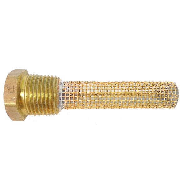
            Spinning wrench has a great drawing….I have no photo that can improve in it. In order the size the fuel tank bungs, consider committing to the hardware that you will use. Each tank outlet will have a finger screen that threads into the bung and receives a male AN fitting. The 3/8” fuel line will take a dash 6 fitting. So take Bob’s Patrol Book, the Tony Bingellis books, and the spruce catalog and make it fit.

            link to finger strainer
            Finger Strainers Finger strainers for fuel tank outlets. Brass fitting has 3/8 inch male pipe thread which fits AN867-3 welding flange, and 1/4

            Brooks Cone
            Southeast Michigan
            Patrol #303, Kit build

            Comment


            • #7
              Thanks Brooks...pics are worth a lot of words! Would anyone be able to post a pic of the wing root rib penetration of fuel lines from the tank? Setup like Bruce (spinningwrench) depicts in his diagram. With fuel tank installed I'm at the point where I need to mark and drill the pass-thru holes and don't like where I have to drill for the nipples off the two fuel feed bungs on the tank.
              All comments appreciated.

              Dave

              Comment


              • #8
                I would source fuel tank fittings from Summit Racing or Pegasus Auto Racing. They are much more compact than the fittings from spruce which I cut quite a bit of material off of before welding them into the tank. For the sight gauges and vent lines you can weld 1/4" male fittings directly to the tank instead of a female fitting to install an AN male fitting. Just be aware you have to protect the threads during construction/installation.

                Comment


                • DBeaulieu
                  DBeaulieu commented
                  Editing a comment
                  Rod, tanks are from AviPro and already constructed. I do have access to a skilled aircraft certified welder but not thrilled with the idea of gouging out the current bungs to install. If the routing for those line are problematic it certainly is a possible solution...thanks for the idea!

                • rodsmith
                  rodsmith commented
                  Editing a comment
                  I wouldn't do that either! Thought you were talking about home built tanks.

              • #9
                I discovered race car fittings after I installed these. The second & third photo shows the forward fuel line. this design conforms to Bob’s Patrol book. The wing line connects to the fuselage fuel line using a rubber hose and two hose clamps. The end of the hard line is beaded to accommodate the rubber hose installation. The red cap cover the bead.

                So, consider installing a flexible line from the tank instead of this hard line. There will be one less joint, and the fitting will be a flare fitting. Seems like an improvement to me.

                IMG_0510.jpg IMG_0511.jpg IMG_0512.jpg
                these show my aft fuel line installation.
                IMG_0516.jpg IMG_0513.jpg FullSizeRender.jpg
                Brooks Cone
                Southeast Michigan
                Patrol #303, Kit build

                Comment


                • #10
                  Thanks Brooks, your fuel lines appear to have more distance from the lightening holes/flanges than I do on my Q/B wing, hence the concern in my situation. I do like the idea of flexible lines from the tank to the fuselage. With fuel tank installed and secured there is still a bit of "jiggle" movement possible by hand. Not sure if hard lines would be best over time, esp as the rubber grommets deteriorate with age and potential for line to rib contact? Servicing those as short runs of rubber flex lines would be a PITA but doable...

                  Comment


                  • #11
                    One option if you need more direction change is where Bruce depicts #7, instead of using a straight nipple, use a 45. Then you can clock it as necessary to offset the route of the lines. Personally I don't like flexible lines for lots of reasons, and only use them going from the firewall to the engine.

                    Comment


                    • #12
                      Jared, I'd be interested in knowing more about the downsides of flexible lines. Would you be willing to share?

                      Comment


                      • #13
                        Originally posted by David Swartzendruber View Post
                        Jared, I'd be interested in knowing more about the downsides of flexible lines. Would you be willing to share?
                        Lifespan:
                        They have a shorter calendar life compared to bent and flared 5052 lines. Often folks cite them being used in race cars as a vote of approval, but race cars are short-lived. We build airplanes for decades of service.

                        Bend Radius:
                        The minimum bend radius is multiples larger than what we can achieve with 5052, and this really matters in the wing root area. Same with how far beyond the fitting you can begin the bend.

                        Size and Weight:
                        The wall thickness of a flexible tube will be much larger than the aluminum tubing, which means it takes up more space. This can be a problem in tight areas like the vertical runs in the cabin. The tubing assembly will weigh much more with long flex line runs.

                        Shop Fabrication:
                        There are flexible lines that can be made in the shop, but it seems the better ones are made on more expensive equipment than the typical builder will have access to.

                        Airframe Abrasion:
                        For braided stainless lines, the jacket can damage the airframe tubes, wires, and just about anything else it rubs against. Of course the solution is proper anchoring and perhaps some padding, but if you get it wrong, it would be most unfortunate for your first indication to be metal removed from something really difficult to replace.

                        I do use flexible braided steel lines where I have to in the brake system, and just cope with all of the disadvantages. But I only use them when I have to, and I worry sometimes builders use them more than necessary out of convenience, familiarity from other hobbies, or just not wanting to learn how to bend and flare the 5052 tubes.

                        Any time I find myself substituting ideal materials, I try and ask myself why. If it is it to save having to learn something, wait for something to arrive, save a little time, to support a prior bias, or something like that, it's a big red flag to remind me it's time to reassess. Sometimes there are worthwhile reasons, sometimes not.

                        Comment


                        • David Swartzendruber
                          David Swartzendruber commented
                          Editing a comment
                          Jared, Thanks for the explanation and the list of things to consider.

                        • svyolo
                          svyolo commented
                          Editing a comment
                          Normal fuel line, including what I got from Spruce is usually pretty poor quality, and a lot of time it is distorted from sitting on a roll. My flexible sections at the wing are Aeroquip Starlite hose. Kevlar braided, very light, but extremely strong and durable. Similar construction to "fuel injection" hose meant to hold pressurized fuel. Very tight min bend radius. I made flare stubs out of the tank thru the first rib, attach the hose to that with double hose clamps, come out the root rib, and 70 degree turn to pick up the hard lines at the root, connected with flare fittings.

                          I tried the cheaper fuel line first, it always flattened out on the turn from the root rib.

                          To me it seems a flex section is a good idea. If the tank moves, it might make the hard line the support for the whole tank. But I have hard lines the rest of the way to the firewall.

                      • #14
                        Just to add to all the excellent points made above, I used very short flexible hose sections to join the fuel lines at the wing root. This was because I couldn't do a trial fit to match the ends until final assembly.

                        The required bends are made in the 3001 fuel line (not the flexible line), with a flared bead at the ends, so the short pieces of flexible line are straight, and easy to get into place (being flexible). Once the wings were mounted we joined the lines with approximately 4" of flexible line that I was able to bend and squeeze into place through the wing root. They slide over the beaded pipe ends and are held in place with hose clamps.

                        It's easy to access and easy to inspect - knowing that at some point it will need replacing. The only other places that flexible lines were used are in the brake system to connect to the pedals, and to connect to the gear legs, both where movement occurs. The pedal lines are easy to inspect anytime. The gear leg connecting lines are a 100 hour inspection item when the floor is out.

                        The photos below show the lines from the tanks to the wing roots and the beading tool (kindly loaned from Simon Nicholson).

                        FBF43E0C-B42E-44D5-A685-392BBB82576B.jpg

                        27B6C9DE-178C-45C4-AF4A-4D026A7DA10F.jpg

                        C628F08E-264D-4C40-892D-4B56D63B2721.jpg

                        8E37E292-23F3-469C-ABDB-5067F081ACEC.jpg
                        Last edited by Nev; 10-02-2023, 03:51 PM.
                        Nev Bailey
                        Christchurch, NZ

                        BearhawkBlog.com - Safety & Maintenance Notes
                        YouTube - Build and flying channel
                        Builders Log - We build planes

                        Comment


                        • #15
                          I like the idea of short flexible lines within the wing root area with beaded connection. That's how I did it on a previous build and I believe it compensates for some movement/vibration between the tank to fuselage fuel pathway. What I didn't like was location of the aft fuel feed for drilling the pass thru (even with a 45 fitting) off the bung. I elected to use a 90 fitting and come out thru the false spar aft of the fuel bay and then out the ribs to the wing root/fuselage space. I havn't made that line yet, but it appears easily doable?
                          90 degree fitting for rear outlet.jpg Rear fuel tank outlet.jpg

                          Comment

                          Working...
                          X