Bearhawk Aircraft Bearhawk Tailwheels LLC Eric Newton's Builder Manuals Bearhawk Plans Bearhawk Store

Announcement

Collapse
No announcement yet.

More advice - ELT aerial

Collapse
X
 
  • Filter
  • Time
  • Show
Clear All
new posts

  • More advice - ELT aerial

    Last night I had the local chapter of the Sport Aircraft Association visit and look over my Bearhawk, which provided a great opportunity to get some advice from members. Many of them have built more than one aircraft and several of them are current or retired aircraft engineers.

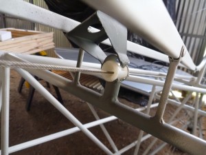
    One suggestion was concerning my location of the ELT aerial inside the rear fuselage, and whether it would work given that it is surrounded by the airframe. My understanding (having not read further yet) is that I need to add a ground-plane around the base of the aerial.

    Has anyone done it in this manner ? Comments ?

    Another suggestion was to invert the lines from my static ports to prevent water ingestion which made immediate sense and was a 2 minute job to fix.

    3A8A0425-2FB8-4E12-884F-D01E6C8DA64D.jpeg

    D5AF7BB5-8B25-47B0-A753-3081DED91288.jpeg
    Nev Bailey
    Christchurch, NZ

    BearhawkBlog.com - Safety & Maintenance Notes
    YouTube - Build and flying channel
    Builders Log - We build planes

  • #2
    I noticed a lot of folks mount their ELT's in the rear of the fuselage. I couldn't find any info on any specific requirement on locating it. I was hoping go put it under the pilot seat to keep the wires short and I can reach down and turn it off and on while seated. That portion of the fuselage is the strongest part of the airframe. If the ELT doesn't survive the crash.................

    Comment


    • #3
      Lots of builders place their ELT's in the back but with a ground plane underneath. That seems to work fine. Mark

      Comment


      • #4
        Not sure about the Artex but ACK specifically says their ELT / antenna is fine inside a tube structure. Provide a good ground plane and you should be good. There's quite a discussion on antenna location and the benefits of having it protected inside a structure. A buddy of mine flipped his Super Cub and buried the tail mounted ELT antenna in the mud, broke it off and it became useless, so there is a case to be made that inside is the safest place for it.

        Comment


        • #5
          I was hoping go put it under the pilot seat to keep the wires short and I can reach down and turn it off and on while seated.
          This was my original plan too. Battson pointed out to me that it could easily be triggered inadvertently by a pax foot, hence me locating it aft of the rear bulkhead. I’ve actually bolted it through the aluminium plate into the frame tabs so it now pretty secure. I plan to locate the ON/OFF/TEST panel in the right-side wing root panel.
          Nev Bailey
          Christchurch, NZ

          BearhawkBlog.com - Safety & Maintenance Notes
          YouTube - Build and flying channel
          Builders Log - We build planes

          Comment


          • #6
            I placed the elt and antenna very similar to yours in the pic. The aluminum pan they are mounted on might be a bit bigger in ours but not much. I will say it all works fine there. During my initial airworthiness inspection, the inspector wanted me to test it and I inadvertently pushed the wrong button and activated it. I quickly discovered my error and turned it back off. Within about 5 minutes my phone was ringing from the Air Force in Florida questioning the signal they had picked up. I explained what happened and apologized and all was fine. Was glad to know that such a quick response was generated and with the airplane in the hangar.

            Comment


            • #8
              That location is fine. American Champion locates all of theirs just behind the baggage bulkhead. I am planning on mounting mine under the passenger seat. You will want a ground plane of at least 1 square foot.

              Comment


              • #9
                I'm planning to mounting the ACK 121.5/406 ELT similar to how Nev mounted the Artex in the pictures above but I have a question about the ground plane. Are most people assuming once a metal plate is attached to the mounting tabs welded to the fuselage tubing, the fuselage tubing acts as the ground plane? The installation instructions I received say the antenna needs to be mounted in the center of a ground plane with a minimum diameter of 24", preferably 48" for maximum power. 24" inches is ~1/4 wavelength of 121.5 MHz, so I understand they're sizing the ground plane to that frequency. If the fuselage tubing isn't the ground plane, then are people just sizing the ground plane to the 406 MHz wavelength since that's the modern frequency? Appreciate the help.
                Colby Osborn
                Mullen/Lincoln Nebraska
                Model 5 Quick Build Kit

                Comment


                • #10
                  This is one of those frustrating situations when the manufacturer cooks up the most ideal scenario they can imagine for their product only, without any regard for the airplane it is going onto, or any other products that will be on it. Sort of like on the first day of school when each of the teachers says their class is the one class that really matters and is going to be the hardest. As a result we are left to decode what is good enough, because clearly we aren't going to be providing the ideal. I considered the fuselage tubes to be good enough.

                  Comment


                  • #11
                    I'm installing the same ELT right now. I called ACK to ask this specific question. They were confident the airframe, if correctly bonded to the antenna mount bracket and the antenna, will act as a ground plane. I'm going to go with that for now and test it once it's installed. The ELT came in the mail yesterday so I'll mount and test it in the next couple weeks and report back.
                    4-Place QB kit #111. First flight May 2022.
                    IO-470 - 260hp

                    Comment


                    • #12
                      Hi guys, I did a deep dive on this - let me share what I've learnt (the hard way, in some cases).

                      ELT Self-damage

                      Without a sufficient ground plane, or if the antenna itself open-circuits (breaks inside, electrically), the high-energy pulses the ELT generates have nowhere to go, when the ELT is turned on. This can easily overheat the ELT's internal circuitry and cause damage (currently irreparable in my case, because Kannad has pulled the SB which allowed that work to occur - although they are still physically able to be repaired - the paperwork does not allow this). In my case, the ground plane was always insufficient, and the antenna broke after around 1,200 flight hours, causing the system to destroy itself - a considerably expensive lesson.

                      This failure scenario would be especially bad if you actually needed your ELT in a real emergency, and it failed shortly you turned it on, as internal components heat up. I strong recommend practical tests to confirm the unit functions every year, but make sure you have a electrical intact antenna (electrically connected from the co-axial plug to the top of the antenna). I suggest testing your antenna with a multimeter BEFORE testing the unit's function, in accordance with local regulations, to avoid causing damage to a perfectly good ELT if the antenna has failed.

                      Ground Plane Design Considerations

                      The ground plane itself can be a wire mesh, solid metal, metal with small lightening holes throughout, whatever - as long as it's conductive and approximately the right shape. The fuselage frame may technically work, but you'll be losing a lot of transmission strength because the ground plane is totally the wrong shape. The 406 MHz frequency was designed to cope with poor antenna situations - but that was done to allow crash damage or an inverted aircraft situation to be overcome. If you "design in" a poor antenna ground plane, then you reduce the chances of a successful rescue when you need it most, particularly if your setup sustains crash damage.

                      The wavelength of the 406 signal dictates the size of the ground plane. The key distance is 1/4 of the wavelength, about 18 centimetres, is the minimum viable ground plane size. You really need an 18 cm circle around your antenna - ideally more, anything over 74 cm is into diminishing returns. Again, this can be wire mesh laid into the inside of the fuselage.

                      You can have holes in the ground plane, up to 1/10th of the wavelength, or around 7 cm in diameter, and electrically the antenna has no idea the hole exists. If the holes are any larger, then it starts to reduce transmission strength in the direction of the hole, from the antenna. The innermost circle around the antenna must be free from holes or gaps, again it's the critical 1/4 wavelength or 18 cm circle that needs to be unbroken around the base of the antenna, or it has a significant impact on overall antenna transmission power. Again, the high-energy 406 pulse is designs to cope with a damaged antenna, but we don't want to design that in.

                      Some say that gaps or "leakage" through a mesh ground plane, or through lightening holes, or even around the sides of the ground plane further out (beyond critical inner 18 cm circle) is generally a good thing, because it means the antenna still has a good chance of getting the signal out when the aircraft crashes in an unusual attitude, or ends up inverted - which is a common crash scenario.

                      These are just my research notes, and I welcome corrections and challenges. I am not an expert, but I have been working with experts lately - and I relish the opportunity to learn from them and share it here.

                      Comment


                      • #13
                        Battson,

                        Like you, I am not an expert in this area, but I am an engineer and also a Ham Radio person, so I have learned about RF signal propagation & antennas. So I know enough to be impressed with your research and reporting!

                        I would like to hijack the string, but still remain practical & relevant. Spoiler alert – ELTs have very serious failures, and “GPS Breadcrumb Trackers” are arguably much better!

                        In the USA, 406 ELT is not mandatory, if you already have a 121.5 ELT. But in Mexico and other countries, 406 is mandatory. So I was bummed at having to install 406 in my Bonanza to be able to fly from the USA to Mexico. So why are all ELTs seriously flawed, despite all the 406 hype? Because the factual data shows they fail to “call the cavalry” about 70% of the time! And the 406 record, despite several impressive technical improvements over 121.5, is not much better. Why? Because, as stated in this string, antennas break, electronics get smashed or burned, signal gets masked by the airframe or terrain or water, etc. On the other hand, 406 does dramatically reduce the false alarms from unintentional activation, because 406 is tied to a specific aircraft with contact details, so a phone call or two will eliminate about 95% of the false alarms.

                        This dark side of the story is rarely told. My research on this was around 2008, but I don’t think much has changed with ELTs. I was alerted to dig deep back then by a highly visible helicopter accident in New Zealand. Michael Erceg was a gazillionaire wine importer in NZ and he went missing in his helicopter. It is a fascinating story of the massive search, and why it failed, and how the wreckage was eventually located 10 days later. Basically, the 406 ELT failed to call the cavalry! So the search relied on the transponder signal, which had poor accuracy and a technical error for location, so they were looking in the wrong place! A private techy guy figured it out over a week later and corrected for the error – and the wreckage (and bodies) was recovered under a very think tree canopy. A fascinating story that parallels the American tragic loss of Steve Fossett. I was directly involved and could tell you all about that – the wreckage was found a year later.

                        As a direct result of that tragic high-profile Erceg crash, a company called Spidertracks was formed in NZ, and it was a rather sophisticated GPS Breadcrumb Tracker. I seem to recall that private money from the Erceg family was donated to fund one of those boxes for many, if not all, private planes in NZ. Full disclosure – I worked with Spidertracks as they began to penetrate the U.S. aviation market. This was all around 2010, I think.

                        Spidertracks - Wikipedia

                        That’s background to other research I did to understand several other studies of the performance of 121.5 & 406 in terms of “calling the cavalry” for real world accidents. That data showed the poor performance I stated above, and I was shocked!

                        Obviously, a breadcrumb tracker has no such failings, because it tracks the aircraft all the way to the site of the accident, or very close to it, depending on the breadcrumb interval chosen. The unit does not need to survive. Also, you can review your breadcrumb on a website, to confirm the system is working. Family & friends can keep track of you, for safety & socially. You can do 2-way texting. The unit is portable and you can use it on your boat or hiking or biking. And there is no installation or certification needed. There is a modest subscription fee, but the initial cost is also modest.

                        These days, probably the best tracker options for personal use are SPOT & InReach. I think Spidertracks has moved to focus on commercial fleet users such as flight schools & rentals.

                        SPOT Satellite Communication Devices | Saved by SPOT | US

                        inReach Satellite Communicators | Messengers | Garmin

                        Spidertracks is now part of Vellox Corporation:
                        Trusted solutions for safe, efficient and compliant operations | Vellox Group

                        None of this relieves you of your obligation to be compliant with aviation regulations, but my purpose here is to debunk the FALSE CONFIDENCE that is natural with ELTs. And the Kiwis on this chat group may be able to correct me with my memory on all this. Other facts & opinions are most welcome.

                        And just think how a Breadcrumb Tracker could have solved the Malaysia Airlines Flight 370 mystery:
                        Malaysia Airlines Flight 370 - Wikipedia

                        ?

                        From Jim Herd

                        Comment


                        • Battson
                          Battson commented
                          Editing a comment
                          Yes, the real-world performance of ELTs - even the 406 beacon - is shockingly poor in terms of successful rescues.

                          Spidertracks is commonly used by New Zealand operators who regularly fly in remote areas of the country. Many commercial fleets have Spidertracks installed in all their aircraft.
                          Last edited by Battson; 05-12-2026, 07:59 PM.

                      • #14
                        Jim and Battson have provided good summaries. I would only add that most radio transmitters will self-destruct if subjected to an open, shorted or very mis-matched load (an antenna that is too long or too short or, for a vertical antenna, has an insufficient ground plane). Even if there is sufficient protection circuitry to protect the transmitter, the output signal will be minimal to none. If you want to be certain that any antenna system is designed and operating properly you can buy a relatively inexpensive ($90 USD) network analyzer. This handy device will graphically show you how the forward/reflected power varies with frequency. For an ELT you should see curves with the low points at or near 121.5 and 406 MHz. As Jim pointed out, this tells you how things are working in your hangar. In an actual crash, all bets are off.

                        As an interesting aside, VFR comm frequencies range from118.000 to 136.975 MHz so if you check your comm antenna with an analyzer you will likely see that the manufacturer has adjusted the antenna for somewhere in the middle.​

                        Comment

                        Working...
                        X