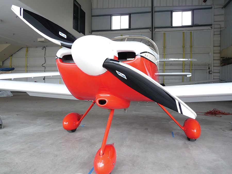
Bearhawk Aircraft Bearhawk Tailwheels LLC Eric Newton's Builder Manuals Bearhawk Plans Bearhawk Store

Announcement

Collapse
No announcement yet.

Cowling exit lip

Collapse
X
 
  • Filter
  • Time
  • Show
Clear All
new posts

  • Cowling exit lip

    I had a nice “win” today when looking to make a cowling exit lip. After trimming the Vans air intake, I was about to throw the trimmed fibreglass away. The shape of it seemed pretty close to what I wanted for the cowl lip. 5 minutes with the angle grinder later and I have what I think should be an effective cowl exit lip.

    This got me thinking. Would there be any merit in mounting the lip on a hinge so it can retract inside the cowl ? Similar to a cowl flap, but less complex. It may create a small amount of turbulence inside the cowl, but probably less than on the outside.

    C0EE91A1-854C-4D21-B5B1-0DA3CA1E75BC.jpeg
    Nev Bailey
    Christchurch, NZ

    BearhawkBlog.com - Safety & Maintenance Notes
    YouTube - Build and flying channel
    Builders Log - We build planes

  • #2
    Fly it like it is, then decide, but I suspect you will need at least that much cowl lip all of the time to avoid cooling issues.

    Comment


    • #3
      Is the cowling lip big enough?

      How much outlet area should I be aiming for ?
      Nev Bailey
      Christchurch, NZ

      BearhawkBlog.com - Safety & Maintenance Notes
      YouTube - Build and flying channel
      Builders Log - We build planes

      Comment


      • #4
        It looks big enough Nev. You want about a 30 degree difference between the line of the cowl bottom and the lip angle to create the best low pressure - according to Bob. Mark

        Comment


        • Mark Goldberg
          Mark Goldberg commented
          Editing a comment
          And often builders have to open up the cowl bottom air outlet to increase the exit area for better cooling. Just consider that possibility when you think about how to attach the lip. Mark

      • #5
        Airspeed is the single biggest factor in cooling a Bearhawk of standard design.

        Prolonged slow flight with part power, or full power, results in heating up the engine to undesirable levels, normally the oil overheats. Sustained climb at full power - forget about it. I have to keep it lean of peak to prevent CHTs going through the roof.

        On the other hand, in winter, I struggle to keep the engine hot enough when running LOP. I leave cowl flaps shut and it still won't warm up.

        I think I am more concerned with engine temps because I have them under my control. Most guys I fly with don't pay close attention to them.

        I assume cowl flaps are slightly less efficient than than a lip, however, I need about 130 to 140 square inches.
        With the flaps shut, I have something like 90 or 80 sq.in exit area, with no lip (no suction).
        These numbers changed since I posted them years ago, as we rebuilt the cowl and enlarged the flaps.
        Last edited by Battson; 06-09-2021, 11:34 PM.

        Comment


        • #6
          Thanks Jon and Mark. I think I’ll aim for around 120 sq inches. I assume that with the lip it should equate to more “virtual” area. That should get me underway for test flying and I can then adjust it from there.
          Nev Bailey
          Christchurch, NZ

          BearhawkBlog.com - Safety & Maintenance Notes
          YouTube - Build and flying channel
          Builders Log - We build planes

          Comment


          • svyolo
            svyolo commented
            Editing a comment
            I have a few "practice" oil cooler plenums. I am thinking of using one of them on the cooler exit, and use scat tube to dump that air outside the cowling side. To me, just dumping it in the lower cowl amounts to a leak from inside the baffles to the lower cowl. Might help both oil cooling and engine cooling.

        • #7
          Prolonged slow flight with part power, or full power, results in heating up the engine to undesirable levels, normally the oil overheats
          Regarding the oil cooler, obviously there’s a number of contributing factors. But how much of a factor do you think the physical location of the oil cooler is ? For instance having mine mounted on the lower firewall I wonder if the outflow from the oil cooler is going to “clash” with the out-flowing cylinder cooling air rather than having a smooth flow of both.
          Nev Bailey
          Christchurch, NZ

          BearhawkBlog.com - Safety & Maintenance Notes
          YouTube - Build and flying channel
          Builders Log - We build planes

          Comment


          • robcaldwell
            robcaldwell commented
            Editing a comment
            I think my oil cooler is mounted in the same locations as yours Nev. My oil temps have been perfect at 175 to 180 F degrees.

        • #8
          There is a ratio that is "recommended" of inlet air area to outlet area I want to say (but am not sure) that it is 1.5 outlet area to 1 inlet area. Tony Bingelis gives this ratio in one of his books.

          Nev, observing how your cooling system works is one of the more important things during your test flying the plane. Just be aware that many builders have had to go back and increase exit area after flying. Myself included. On most all my planes. To improve cooling. Mark

          Comment


          • coosbo
            coosbo commented
            Editing a comment
            In his blue book he says "Ordinarily most builders provide a slightly larger area (about 10 per cent larger) for the air outlet than for the inlet opening."
            In the paragraph immediately before he also states "Some builders and manufacturers (also in desperation) resort to the installation of a large, deflection lip along the bottom opening in an effort to create a sort of venturi-like low pressure area to improve the airflow through the engine cowling. If you have to depend upon this double-ugly solution, you should probably restudy your cowling and cooling installation and rework it."
            I'm guessing some of Tony's general cowling advice doesn't necessarily apply directly to the BH?

        • #9
          Where are we basing the opening measurement? Is it firewall forward / tunnel forward? Or is the tunnel area also included in the total square inches?
          Rob Caldwell
          Lake Norman Airpark (14A), North Carolina
          EAA Chapter 309
          Model B Quick Build Kit Serial # 11B-24B / 25B
          YouTube Channel: http://bearhawklife.video
          1st Flight May 18, 2021

          Comment


          • Battson
            Battson commented
            Editing a comment
            At right angles to the direction of airflow (normal to the flow), include all open areas where air exits the cowl.
            Last edited by Battson; 06-10-2021, 05:42 PM.

        • #10
          Originally posted by Nev View Post

          Regarding the oil cooler, obviously there’s a number of contributing factors. But how much of a factor do you think the physical location of the oil cooler is ? For instance having mine mounted on the lower firewall I wonder if the outflow from the oil cooler is going to “clash” with the out-flowing cylinder cooling air rather than having a smooth flow of both.
          The main thing is the supply of cold air to the front of the cooler, heat transfer is more efficient when the air is moving more slowly through the cooler, so the air has time to heat up and remove the heat.

          Because of the drag through the cooling fins (engine or cooler), you need a larger cowl exit area to help suck the air out. The pressure on the inlet side isn't enough, on it's own. Hence 1:1.5 ratio. There should be an oversupply of air to the front side of the cooling fins. A pressure bubble, in other words. This is why cowls lift upwards in flight, relative to the engine. Of course a plenum solves that issue.

          I have a 3" inlet SCAT to my 12 pass cooler. It is not enough. Once up a time, I had the whole frontal area of the oil cooler exposed to the oncoming airflow, that was ideal - the oil ran very cool.

          Another consideration, the longer the tube into the cooler, and the more bends in the tube - the greater the loses. You can use SKEET to improve this. My tube is about 12" long, with a 90 degree bend.

          Opening my cowl flaps makes a considerable difference to oil temperature, so I assume that suction on the outlet side of the cooler is all that's required. The cowl flaps create so much suction, that part of the top cowl pops inside out when I open them fully (standard design for top cowl).
          Last edited by Battson; 06-10-2021, 05:45 PM.

          Comment


          • #11
            Since I’m running a different engine my info doesn’t apply for the most part. I just wanted to say that I personally agree with Tony and think the cowl lip is a rudimentary fix. However, lots of manufacturers have and still are using it. I was unwilling to put a lip on my Luscombe and felt the same about my BH.

            The Continental IO360 is known for being hard to cool; an unfair reputation IMO. I have 80sqin of cowl exit area at the tunnel and a significant portion of that is blocked by my muffler. I forgot to measure my cowl flaps but they probably double the outlet area. During the summer I need to leave my cowl flaps partially open most of the time, unless I’m above 10k ft, and with them fully open I can climb unrestricted. During the winter I can fly with the flaps closed and the engine at nice warm temperatures.

            All this oil cooler placement and ducting mumbo jumbo…shoulda used a Continental. 😉
            Scratch Built 4-place Bearhawk. Continental IO-360, 88" C203 McCauley prop.

            Comment


            • #12
              I would be tempted to try it with out the lip first. A friend took one off his Murphy and it went about 4mph faster. We have a Continental IO-360 that runs cool with no cowl lip. There is even a pc of cardboard on the oil cooler in summer. So far there have been no cooling issues and our mechanic says we have very efficient cooling. We made aluminum baffles that fit tight around the engine. There is about a 2-3" rubber gap seals on the baffles that are bent slightly inward with the cowl and nosebowl on to seal the top of the engine off. If you can get the nose bowl as close to the spinner as reasonable. I think the space between our spinner and nose bowl is 3/8" max. When I was reading up on pressure cowls, LO-Presti's, James engineering etc a big topic was sealing the engine in and trying to minimize the air drawn out by the spinner. It has been a while but I believe it was as high as 20% of the air in the inlets can be drawn out by the prop. The Continental IO360 has the fuel system on top that does not make a true pressure cowl so we sealed the top of the engine tight to the cowl and nose bowl to emulate a pressure cowl. The advantage of a pressure cowl is if the space over the engine is pressurized that puts the air through the cylinders efficiently. If it is possible to seal between the engine and nose bowl around the prop opening that is a bonus. Then look at the configuration under the engine and try to make it as clean as possible to duct the air out. We used a custom 3 into 1 exhaust headers that run parallel to the engine that left the underside wide open to take the air out efficiently.

              For the nosebowl I had to custom form a nose bowl so I fiberglassed a thin duct half into the top half of the nose bowl and made removable aluminum bottom duct halves. The aluminum duct bottom and fiberglass duct half was intended to form a duct to project air up into the cavity over the engine so it did not stumble over the front of the engine. The front cylinders were too cold so we took out the aluminum bottom duct halves so now the cylinders are fairly uniform for cooling. My partner wanted to put cooling vents in but I did not want to do fixes for issues if none was required. The more efficient the cooling the less drag the cooling creates. Everything I read was the inlet openings are two big. I started with the MC3a nosebowl and made a custom lower half to work with our Continental. While I was at it I took and vertical inch out of both inlets. Main reason was to protect the fuel pump and lines inside the nose bowl. The downsized inlets did no harm.

              I used to subscribe to Kitplanes and they always had great articles. One of the biggest issues for homebuilders is cooling. I was on other forums reading about builders struggles so I tried to incorporate as much as possible into cooling during the build as possible. There were a lot of good information on the Web by Zavaston on cooling his racing Lancair. My research started with the attached article from Kitplanes. The information is Lycoming based but we put our own spin on it for the Continental as a pressure cowl with fuel & air induction on top a maintenance headache.

              Schmidbauer wrote book(s) on how he got his Mustang flying at 262mph and he likely has gone past that as I quit following a long time ago. There is a lot of valuable information there. I used to be on the James aircraft forums for the pressure cowl information.

              I scanned Zavaston's Kitplane article on cooling and pressure cowls. He is an engineer and did an amazing amount of research. This is the condensed version of his his cooling results. This is a good read and with any luck his information may still be hanging out on the web. Best advice I can give is learn as much as you can on the subject and the results may be surprising. Hope this is of some value to you.
              Glenn
              Attached Files
              Last edited by Glenn Patterson; 07-02-2021, 07:30 AM.

              Comment


              • #13
                This is a follow up to my comment on cooling. The Continental IO360 threw a few challenges like the engine mount, fuel system return and the nose bowl. Bob Barrows gave us the tube sizes and layout to modify the engine bed mount for a Cessna 337 Skymaster to the BH 4 place. We were able to get a bed mount for $100 that needed some repairs. One partner was a certified welder so no issues with getting the bed mount. One photo shows the modifications to the top half of the nose bowl to fit over the engine. I sectioned across the top and raised it an inch and glassed that squiggle. I cut the inside of each bowl inlet and moved them outward an inch and glassed the gaps in. That got the fuel pump and fuel lines tucked in behind the nose bowl. It also got the inlets so no inlet was behind the spinner blocking off that space to have the nose clean at the spinner. The white gelcoat gives an indication of how modified that half was. I used the bottom half to make a mould. I made an outline of what the lower nose bowl needed to be to fit over the end of the bed mount on plywood. I used Bondo on the lower half to sculpt the shape & templated left to right for symmetry. When I was happy then I used paste wax for mould release and laid fiberglass over the lower bowl to make a stiffened female mould. Waxed the female mould and built the lower half with fiberglass and West epoxy. The top and bottom were cut to mate up. The Continental IO360 made some challenges but in the end allowed a very clean firewall forward cowl & nose that made over coming the unique engine worth the effort.
                Attached Files

                Comment


                • #14
                  Here are a couple good Kitplane articles on cooling. The third photo in the first article is one that most builders could build. It shows how the cooling baffles will seal against the upper cowl to retain the cooling air pressure over the engine. https://www.kitplanes.com/engine-the...ding-meltdown/

                  All the articles that I read on cooling is to seal the top baffles and fill in anywhere air can escape. Air that escapes the baffling is tramp air that is going to increase the air volume trying to exit the cooling to exit the cowl. The ideal is all the air goes through the engine with no leakage. The emphasis in all the articles is sealing the top of the engine to eliminate any leakage.

                  How to keep your engine’s carburetor or fuel-injection system breathing right. By Dave Prizio.

                  Comment


                  • #15
                    Be carful adding a lip, it may disrupt the airflow enough that you lose the airflow and venturi effect on the cowl exit and actually lose cooling. That's a comment I've heard from a few guys flying Murphy's on floats, where cooling is a huge issue.

                    Comment


                    • Battson
                      Battson commented
                      Editing a comment
                      That is an interesting perspective, however it would depend entirely on the design of the lip - as with all things aerodynamic, shape is all important.
                  Working...
                  X